serial communication
Serial port
Serial interface is abbreviated as serial port, also known as serial communication interface or serial communication interface (usually COM interface), which is an extended interface using serial communication mode. Serial interface refers to the sequential transmission of data bit by bit. Its characteristic is that the communication line is simple. As long as a pair of transmission lines, two-way communication can be realized (the telephone line can be directly used as the transmission line), which greatly reduces the cost. It is especially suitable for long-distance communication, but the transmission speed is slow.
-
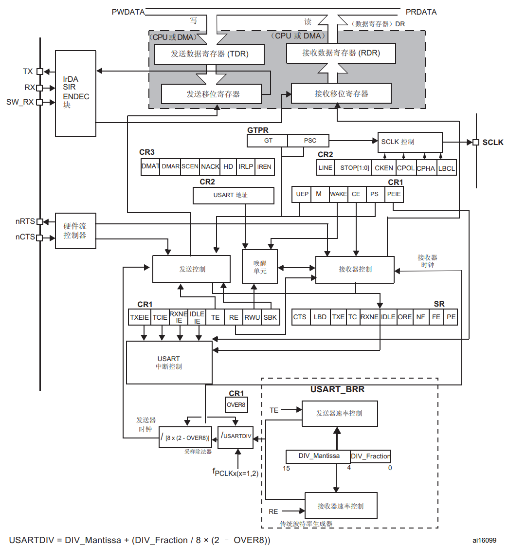
USART (universal synchronous asynchronous receiver and transmit): universal synchronous asynchronous transceiver
- USART is a serial communication device, which can flexibly exchange full duplex data with external devices.
-
UART(universal asynchronous receiver and transmitter): universal asynchronous transceiver
- Asynchronous serial communication port (UART) is what we often call serial port in embedded system. It is also a general data communication protocol.
difference:
USART refers to a port module of single chip microcomputer, which can be configured into synchronous mode (SPI, I2C) or asynchronous mode as required. The latter is UART. Therefore, UART can be called a "Protocol" equivalent to SPI and I2C, while USART is not a protocol, but should be understood as an entity.
Compared with synchronous communication, UART does not need a unified clock line and wiring is more convenient. However, in order to decode the signal normally, both parties using UART communication must agree on the baud rate in advance, that is, the number of transmitted symbols in a unit event.
Supplement:
In the field of electronic communication, baud (modulation Rate) refers to the Rate at which the effective data signal modulates the carrier, that is, the number of carrier modulation state changes in unit time. It is a measure of symbol transmission Rate. 1 baud refers to transmitting 1 symbol per second. Through different modulation methods, multiple bit signals can be loaded on one symbol. [1] "Baud" itself is a Rate, so it does not need to be written as Baud Rate (Rate is a redundant word). The unit "baud" itself represents the modulation number per second. Taking "Baud per second" as the unit is a common error, but in general spoken Chinese communication, "baud" is often described by "Baud Rate".
USART interrupt
[external chain picture transfer failed. The source station may have anti-theft chain mechanism. It is recommended to save the picture and upload it directly (img-vkffevl6-1632828582303)( https://raw.githubusercontent.com/Nepqiu/gallery/master/img/image-20210815155528305.png )]
USART interrupt events are connected to the same interrupt vector:
- During transmission: when transmission is completed and cleared, the transmission or transmission data register is the air break.
- During reception: idle line detection, overflow error, received data register is not empty, parity error, LIN open circuit detection, noise flag (multi buffer communication only) and frame error (multi buffer communication only)
[external chain picture transfer failed. The source station may have anti-theft chain mechanism. It is recommended to save the picture and upload it directly (img-ibzhqtpl-1632828582305)( https://raw.githubusercontent.com/Nepqiu/gallery/master/img/image-20210811170712630.png )]
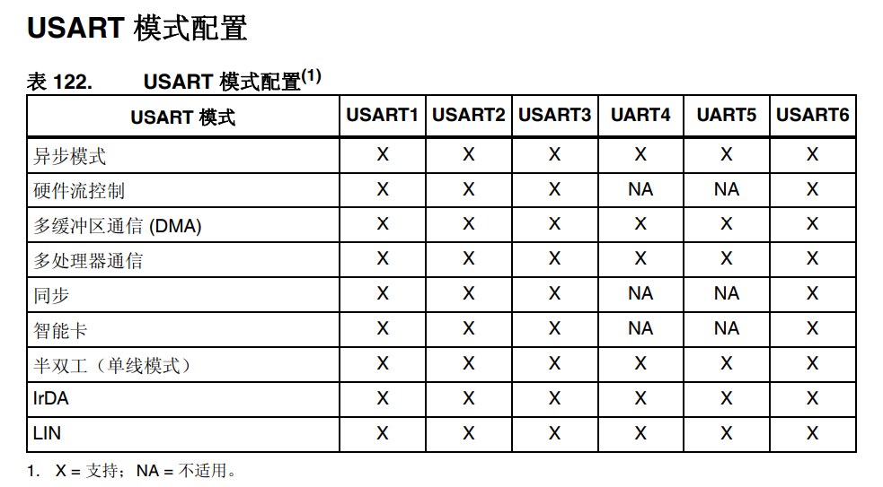
Serial port mode configuration
Continuous communication using DMA
USART can use DMA for continuous communication. DMA requests for the receive buffer and the transmit buffer are independent.
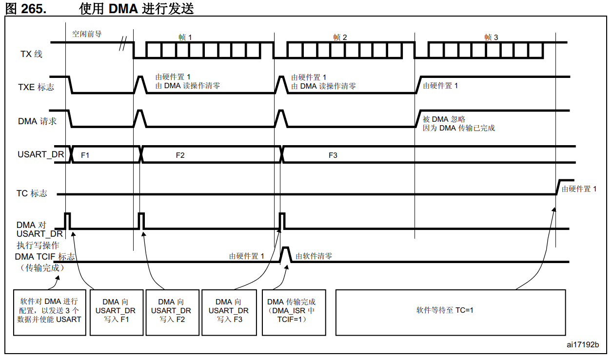
Send using DMA
Sending using DMA will USART_ DMAT position 1 in CR3 register can enable DMA mode transmission. When TXE is in position 1, data can be loaded from SRAM area (configured by DMA, see DMA section) to USART_DR register. To map a DMA channel for USART transmission, follow the steps below (x indicates the channel number):
-
Write USART in DMA control register_ Dr register address, which is configured as the destination address of the transmission. After each TXE event, data is moved from memory to this address.
-
Write the memory address in the DMA control register and configure it as the source address of the transmission. After each TXE event, data will be loaded from this storage area into USART_ In the Dr register.
-
Configure the total number of bytes to be transferred in the DMA control register.
-
Configure the channel priority in the DMA register.
-
According to the requirements of the application, DMA interrupt is generated after half or all of the transmission is completed.
-
Write 0 to the TC bit in the SR register and clear it.
-
Activate the channel in the DMA register.
When the amount of data transfer set in the DMA controller is reached, the DMA controller will generate an interrupt on the interrupt vector of the DMA channel.
In the transmit mode, after DMA performs a write operation on all data to be transmitted (TCIF flag in DMA_ISR register is set to 1), the TC flag can be monitored to ensure that USART communication has been completed. This step must be performed before disabling USART or entering stop mode to avoid damaging the last transmission. The software must wait until TC=1. The TC flag must be cleared during all data transmission, and then set to 1 by the hardware after the transmission of the last frame.
Receive using DMA
Use USART_ DMAR position 1 in CR3 register can enable DMA mode reception. When receiving data bytes, the data is transferred from USART_ The Dr register is loaded into the SRAM area (configured by DMA, see DMA specification). To map a DMA channel for USART reception, follow these steps:
-
Write USART in DMA control register_ Dr register address, which is configured as the source address of the transmission. After each RXNE event, data is moved from this address to memory.
-
Write the memory address in the DMA control register and configure it as the target address for transmission. After each RXNE event, the data is retrieved from USART_ The Dr register is loaded into this store.
-
Configure the total number of bytes to be transferred in the DMA control register.
-
Configure the channel priority in the DMA control register.
-
According to the requirements of the application, an interrupt is generated after half or all of the transmission is completed.
-
Activate the channel in the DMA control register.
When the amount of data transfer set in the DMA controller is reached, the DMA controller will generate an interrupt on the interrupt vector of the DMA channel. In the interrupt subroutine, USART_ DMAR bit in CR3 register shall be cleared by software.Note: if DMA is used for reception, do not enable RXNEIE bit
[external chain picture transfer failed. The source station may have anti-theft chain mechanism. It is recommended to save the picture and upload it directly (img-npkqgbln-1632828582308)( https://raw.githubusercontent.com/Nepqiu/gallery/master/img/image-20210811171131932.png )]
Error flag and interrupt generation in multi buffer communication
In multi buffer communication, if any error occurs in the transaction, an error flag will be placed after the current byte. If the interrupt enable is set to 1, an interrupt will be generated. During single byte reception, the frame error, overflow error and noise flags set together with RXNE have separate error flag interrupt enable bits (EIE bit in USART_CR3 register); If this position is 1, an interrupt will be generated after the current byte due to any one of these errors.
programming
Receiving method:
- DMA receive interrupt receive
- DMA + serial port + DMA idle interrupt reception
- DMA double buffer + serial port + DMA idle interrupt reception
- DMA + serial port + DMA idle interrupt + ring queue reception
Sending method:
- DMA + serial port transmission
- Single serial port transmission
- DMA + serial port sending + ring queue (double buffer)
- FIFO for dynamic memory allocation
The following mainly uses ring queue + DMA + non dynamic memory allocation + IDLE interrupt
It is recommended to read the reference article at the bottom first
Receiving process
USART1 + DMA + IDLE interrupt + lockless queue
Main function:
int main(void)
{
    uint8_t buff_read[32];
    uint32_t length;

    usart1_init();

    while (1)
    {
        length = fifo_read_buff(pfifo_x, buff_read, 32);
        if (length)
        {
            printf("lengtt = %d", length); // Actual received data length
            //Process the received data
        }
        else
        {
            printf("no data rx");// no data
        }

        if (pfifo_x->error)
        {
            printf("fifo error %d", pfifo_x->error);// Receive error
            pfifo_x->error = 0;
        }
    }
}
Interrupt handling function:
void USART1_IRQHandler(void) // Receive data interrupt
{
    __IO uint8_t Len = 0;

    //Send completion interrupt
    /*
	 * DMA When interrupted, it only means that all data bytes to be transmitted have been transmitted to the transmission data register of the serial port.
	 * At this time, the serial port actually has 2 bytes to send, and the 2 bytes in the data register and shift register need to be sent. The serial port transmission cannot be turned off.
	 * Similarly, if it is 485 switching direction, it must wait until the transmission is completed, that is, the shift register transmission is completed - TC flag is set.
	 *
	 * TXE It means that the transmit buffer DR is empty, and TC means that the SHIFT register is empty.
	 * DMA Completion only means that the last byte is sent to the DR register. At this time, one byte of the SHIFT register is starting to be sent,
	 * DR There is a byte waiting to be sent in the register, so 2 bytes have not been sent.
	 */
    if (USART_GetITStatus(USART1, USART_IT_TC) == SET)
    {
        USART_ClearITPendingBit(USART1, USART_IT_TC);
        USART_ITConfig(USART1, USART_IT_TC, DISABLE);
        DMA2_Stream7_working = 0;
    }
    //Bus idle interrupt
    if (USART_GetITStatus(USART1, USART_IT_IDLE) != RESET) //Trigger interrupt flag bit
    {
        Len = USART1->SR;                           //Clear RXNE flag
        Len = USART1->DR;                           //Clear USART_IT_IDLE flag
        Len = DMA_GetCurrDataCounter(DMA2_Stream5); //Function to get the current remaining data size

        if (pfifo_1 != 0)
        {
            // Len is the current receive index
            pfifo_1->in += ((pfifo_1->last_cnt - Len) & (pfifo_1->size - 1)); //Update in
            pfifo_1->last_cnt = Len;

            if ((pfifo_1->in - pfifo_1->out) > pfifo_1->size)
            {
                pfifo_1->out = pfifo_1->in; // Empty the cache and pay attention to the assignment order. Pfifo - > in = pfifo - > out is wrong
                pfifo_1->error |= FIFO_DMA_ERROR_RX_FULL;
            }
        }
        else
        {
            pfifo_1->error |= FIFO_DMA_ERROR_RX_POINT_NULL;
        }
    }
}
Initialization (Standard Library)
#define USART1_RX_LEN 32
#define USART1_TX_LEN 32
uint8_t Usart1_Rx[USART1_RX_LEN] = {0};
uint8_t Usart1_Tx[USART1_TX_LEN] = {0};
uint8_t Usart1_Tx_Buffer[USART1_TX_LEN] = {0};

fifo_rx_def fifo_usart_rx_1;
fifo_rx_def *pfifo_1 = &fifo_usart_rx_1;
fifo_rx_def fifo_usart_tx_1;

uint8_t DMA2_Stream7_working = 0;

void usart1_init(void)
{

    /* -------------- Enable Module Clock Source ----------------------------*/
    RCC_AHB1PeriphClockCmd(RCC_AHB1Periph_GPIOA, ENABLE);  //Enable GPIOA clock
    RCC_APB2PeriphClockCmd(RCC_APB2Periph_USART1, ENABLE); //Enable USART1 clock

    GPIO_PinAFConfig(GPIOA, GPIO_PinSource9, GPIO_AF_USART1);  //GPIOA9 multiplexed to USART1
    GPIO_PinAFConfig(GPIOA, GPIO_PinSource10, GPIO_AF_USART1); //GPIOA10 multiplexed to USART1

    /* -------------- Configure GPIO ---------------------------------------*/
    {
        GPIO_InitTypeDef GPIO_InitStruct;
        NVIC_InitTypeDef NVIC_InitStructure;
        USART_InitTypeDef USART1_InitStruct;

        //USART1 port configuration
        GPIO_InitStruct.GPIO_Pin = GPIO_Pin_9 | GPIO_Pin_10; //GPIOA9 and GPIOA10
        GPIO_InitStruct.GPIO_Mode = GPIO_Mode_AF;            //Reuse function
        GPIO_InitStruct.GPIO_Speed = GPIO_Speed_50MHz;       //Speed 50MHz
        GPIO_InitStruct.GPIO_OType = GPIO_OType_PP;          //Push pull multiplex output
        GPIO_InitStruct.GPIO_PuPd = GPIO_PuPd_UP;            //Pull up
        GPIO_Init(GPIOA, &GPIO_InitStruct);                  //Initialize PA9, PA10

        //USART1 initialization settings
        USART_DeInit(USART1);
        USART1_InitStruct.USART_BaudRate = 115200;                                    //Baud rate setting
        USART1_InitStruct.USART_WordLength = USART_WordLength_8b;                     //The word length is in 8-bit data format
        USART1_InitStruct.USART_StopBits = USART_StopBits_1;                          //A stop bit
        USART1_InitStruct.USART_Parity = USART_Parity_No;                             //No parity bit
        USART1_InitStruct.USART_HardwareFlowControl = USART_HardwareFlowControl_None; //No hardware data flow control
        USART1_InitStruct.USART_Mode = USART_Mode_Rx | USART_Mode_Tx;                 //Transceiver mode
        USART_Init(USART1, &USART1_InitStruct);                                       //Initialize serial port 1

        USART_Cmd(USART1, ENABLE); //Enable serial port 1
        USART_ClearFlag(USART1, USART_FLAG_TC);

        //Usart1 NVIC configuration
        NVIC_InitStructure.NVIC_IRQChannel = USART1_IRQn;         //Serial port 1 interrupt channel
        NVIC_InitStructure.NVIC_IRQChannelPreemptionPriority = 1; //Preemption Priority
        NVIC_InitStructure.NVIC_IRQChannelSubPriority = 0;
        NVIC_InitStructure.NVIC_IRQChannelCmd = ENABLE; //IRQ channel enable
        NVIC_Init(&NVIC_InitStructure);                 //Initializes the VIC register according to the specified parameters

        USART_ITConfig(USART1, USART_IT_RXNE, ENABLE); //Turn on related interrupt
        USART_ITConfig(USART1, USART_IT_TC, DISABLE);
        USART_ITConfig(USART1, USART_IT_IDLE, ENABLE);
    }

    /* -------------- Configure DMA -----------------------------------------*/
    /* send out */
    {
        DMA_InitTypeDef DMA_InitStruct;
        NVIC_InitTypeDef NVIC_InitStructure;

        RCC_AHB1PeriphClockCmd(RCC_AHB1Periph_DMA2, ENABLE);

        //send data
        DMA_Cmd(DMA2_Stream7, DISABLE); //Turn off DMA
        DMA_DeInit(DMA2_Stream7);       //Reset to default
        DMA_InitStruct.DMA_Channel = DMA_Channel_4;
        DMA_InitStruct.DMA_PeripheralBaseAddr = (uint32_t) & (USART1->DR);   //source address
        DMA_InitStruct.DMA_Memory0BaseAddr = (uint32_t)(Usart1_Tx);          //Destination address
        DMA_InitStruct.DMA_DIR = DMA_DIR_MemoryToPeripheral;                 //The data transmission direction is from peripherals to memory
        DMA_InitStruct.DMA_BufferSize = USART1_TX_LEN;                       //Sets the buffer size of the data
        DMA_InitStruct.DMA_PeripheralInc = DMA_PeripheralInc_Disable;        //The peripheral address remains unchanged
        DMA_InitStruct.DMA_MemoryInc = DMA_MemoryInc_Enable;                 //Memory buffer address self addition
        DMA_InitStruct.DMA_PeripheralDataSize = DMA_PeripheralDataSize_Byte; //8-bit byte transfer
        DMA_InitStruct.DMA_MemoryDataSize = DMA_MemoryDataSize_Byte;         //The data width is 8 bits
        DMA_InitStruct.DMA_Mode = DMA_Mode_Normal;                           //Operating in normal mode
        DMA_InitStruct.DMA_Priority = DMA_Priority_VeryHigh;                 //Highest priority
        DMA_InitStruct.DMA_FIFOMode = DMA_FIFOMode_Disable;
        DMA_InitStruct.DMA_FIFOThreshold = DMA_FIFOThreshold_1QuarterFull;
        DMA_InitStruct.DMA_MemoryBurst = DMA_MemoryBurst_Single;
        DMA_InitStruct.DMA_PeripheralBurst = DMA_PeripheralBurst_Single;
        DMA_Init(DMA2_Stream7, &DMA_InitStruct);

        NVIC_InitStructure.NVIC_IRQChannel = DMA2_Stream7_IRQn;
        NVIC_InitStructure.NVIC_IRQChannelPreemptionPriority = 2;
        NVIC_InitStructure.NVIC_IRQChannelSubPriority = 0;
        NVIC_InitStructure.NVIC_IRQChannelCmd = ENABLE;
        NVIC_Init(&NVIC_InitStructure);

        DMA_ITConfig(DMA2_Stream7, DMA_IT_TC, ENABLE); //Enable send completion interrupt
        DMA_Cmd(DMA2_Stream7, DISABLE);
        USART_DMACmd(USART1, USART_DMAReq_Tx, ENABLE); //Enable DMA transmission of serial port

        if (fifo_init(&fifo_usart_tx_1, Usart1_Tx_Buffer, USART1_TX_LEN) == -1)
        {
            // Must be to the power of 2
        }
    }
    // receive data
    {
        DMA_InitTypeDef DMA_InitStruct;

        RCC_AHB1PeriphClockCmd(RCC_AHB1Periph_DMA2, ENABLE);

        DMA_Cmd(DMA2_Stream5, DISABLE); //Turn off DMA
        while (DMA_GetCmdStatus(DMA2_Stream5) != DISABLE)
            ;
        DMA_DeInit(DMA2_Stream5); //Reset to default
        DMA_InitStruct.DMA_Channel = DMA_Channel_4;
        DMA_InitStruct.DMA_PeripheralBaseAddr = (uint32_t) & (USART1->DR);   //source address
        DMA_InitStruct.DMA_Memory0BaseAddr = (uint32_t)(Usart1_Rx);          //Destination address
        DMA_InitStruct.DMA_DIR = DMA_DIR_PeripheralToMemory;                 //The data transmission direction is from peripherals to memory
        DMA_InitStruct.DMA_BufferSize = USART1_RX_LEN;                       //Sets the buffer size of the data
        DMA_InitStruct.DMA_PeripheralInc = DMA_PeripheralInc_Disable;        //The peripheral address remains unchanged
        DMA_InitStruct.DMA_MemoryInc = DMA_MemoryInc_Enable;                 //Memory buffer address self addition
        DMA_InitStruct.DMA_PeripheralDataSize = DMA_PeripheralDataSize_Byte; //8-bit byte transfer
        DMA_InitStruct.DMA_MemoryDataSize = DMA_MemoryDataSize_Byte;         //The data width is 8 bits
        DMA_InitStruct.DMA_Mode = DMA_Mode_Circular;                         //Working in circular cache mode
        DMA_InitStruct.DMA_Priority = DMA_Priority_VeryHigh;                 //Highest priority
        DMA_InitStruct.DMA_FIFOMode = DMA_FIFOMode_Disable;
        DMA_InitStruct.DMA_FIFOThreshold = DMA_FIFOThreshold_1QuarterFull;
        DMA_InitStruct.DMA_MemoryBurst = DMA_Mode_Normal; //DMA_MemoryBurst_Single;//
        DMA_InitStruct.DMA_PeripheralBurst = DMA_PeripheralBurst_Single;
        DMA_Init(DMA2_Stream5, &DMA_InitStruct);

        DMA_Cmd(DMA2_Stream5, ENABLE);
        USART_DMACmd(USART1, USART_DMAReq_Rx, ENABLE);

        if (fifo_init(pfifo_1, Usart1_Rx, USART1_RX_LEN) == -1)
        {
            // Must be to the power of 2
        }
    }
}
Sending process
In the process of designing serial port driver, the criteria to be followed are:
- Minimize program running time
- Minimize the memory occupied by the program
Enable serial port sending completion interrupt
void USART1_IRQHandler(void) // Receive data interrupt
{
    __IO uint8_t Len = 0;

    //Send completion interrupt
    /*
	 * DMA When interrupted, it only means that all data bytes to be transmitted have been transmitted to the transmission data register of the serial port.
	 * At this time, the serial port actually has 2 bytes to send, and the 2 bytes in the data register and shift register need to be sent. The serial port transmission cannot be turned off.
	 * Similarly, if it is 485 switching direction, it must wait until the transmission is completed, that is, the shift register transmission is completed - TC flag is set.
	 *
	 * TXE It means that the transmit buffer DR is empty, and TC means that the SHIFT register is empty.
	 * DMA Completion only means that the last byte is sent to the DR register. At this time, one byte of the SHIFT register is starting to be sent,
	 * DR There is a byte waiting to be sent in the register, so 2 bytes have not been sent.
	 */
    if (USART_GetITStatus(USART1, USART_IT_TC) == SET)
    {
        USART_ClearITPendingBit(USART1, USART_IT_TC);
        USART_ITConfig(USART1, USART_IT_TC, DISABLE);
        DMA2_Stream7_working = 0;
    }
}
Enable DMA send completion interrupt
//uint8_t DMA2_Stream7_working = 0;

/**
  * @brief          Send completion interrupt
  * @param[in]      void
  * @retval         void
  */
/*
 * ST The official has APPNOTE guidance (for the single chip microcomputer model without RS485 function of UART):
 * 1,Before starting DMA, turn off UART transmission completion interrupt and clear the transmission completion interrupt flag;
 * 2,In DMA transmission completion interrupt function, enable UART transmission completion interrupt;
 * 3,In UART transmission completion interrupt function, switch RS485 to receive state;
*/
void DMA2_Stream7_IRQHandler(void)
{
    if (DMA_GetITStatus(DMA2_Stream7, DMA_IT_TCIF7) != RESET)
    {
        DMA_ClearFlag(DMA2_Stream7, DMA_IT_TCIF7);
        DMA_Cmd(DMA2_Stream7, DISABLE); //Disable transmission
        //while (DMA_GetCmdStatus(DMA2_Stream7) != DISABLE);
        USART_ITConfig(USART1, USART_IT_TC, ENABLE);

        //DMA2_Stream7_working = 0;
    }
}
DMA transmit function
//uint8_t DMA2_Stream7_working = 0;

/**
  * @brief          Serial port 1 + DMA transmission
  * @param[in]      *data: Data to be sent
  * @param[in]      len: Size of data
  * @retval         void
  */
uint32_t usart1_dma_send(uint8_t *data, uint16_t len)
{
    uint32_t result = fifo_write_buff(&fifo_usart_tx_1, data, len); //Put data into circular buffer

    //result != 0 indicates that the data is successfully put into DMA2_Stream6_working == 0 indicates that there is no data in the buffer
    if (DMA2_Stream7_working == 0 && result != 0)
    {
        len = fifo_read_buff(&fifo_usart_tx_1, Usart1_Tx, USART1_TX_LEN); //Get data from circular buffer

        DMA_SetCurrDataCounter(DMA2_Stream7, len); //Set transmission length
        DMA_Cmd(DMA2_Stream7, ENABLE);             //Enable transmission

        DMA2_Stream7_working = 1;
    }

    if (result == len)
    {
        return len;
    }
    else
    {
        return result;
    }
}
analysis
https://www.amobbs.com/thread-4516795-1-1.html
When stm32 uses dma to transmit serial port data, when dma interrupt transmission is completed
Procedure 1
/*The pointer points to ptr and needs to send count data*/
void USART1WriteDataToBuffer(*ptr,u8 count)
{
    /*Judge whether the data has been sent*/
    while(count--)
    {
        /*send data*/
        USART1SendByte(*ptr++);
        /*Wait until this data is sent, and then enter the next data sending process*/
        while(USART_GetFlagStatus(USART1, USART_FLAG_TC);
    }
    /*After sending the data, return*/
}
This program will have disastrous consequences in practical application. First of all, after sending data to the register is started, the CPU has been waiting for the data to be sent. In this way, the CPU can not do other things until all the data to be sent are completed. Compared with the running speed of the CPU core, the running speed of serial peripherals is very fast. If a very fast device waits for a relatively slow device, the efficiency of the program is very low.
So try to send data by interrupt
Procedure 2
/*Write data to send buffer*/
void USART1WriteDataToBuffer(*ptr,u8 count)
{
    while (count != '\0')
    {
        USART1SendTCB[Index++] = *ptr++;
        Count = count;
    }
    /***Determine whether overflow and other codes are omitted***/
}
/***ISR sending interrupt***/
void USART1SendUpdate(void)
{
    /***Judge whether the data in the transmission buffer has been sent***/
    /***Send the data in the send buffer***/
    USART1SendByte( *ptr++ ); /***Send pointer plus one, number of bytes to be sent minus one, etc***/
}
In this way, when the USART1WriteDataToBuffer function is called, we write the data to be sent into the transmission buffer, and the CPU can perform other tasks. After a data transmission is completed, the interrupt ISR will be triggered, write the next data into the transmission register in the interrupt service program, and start the next transmission until the transmission is completed.
However, in practical engineering applications, this similar situation is often encountered. The serial port display needs to display 1000 points, and the RGB annual value of the color of these 1000 points is sent through the serial port. After the 1000 data are written into the transmission register, the transmission is started. At the baud rate of 115200, one start bit and one stop bit. In the case of no check bit, it takes at least (10 * 1000 * 2) / 115200 = 0.1736 seconds. During this period, the clock is updated and a string of time update data needs to be sent. There are about 100 data, so this string of data needs to be written to the transmission byte of the transmission buffer.
Similarly, if the display task is updated at this time, other data will be written to the buffer.
[the external chain picture transfer fails. The source station may have an anti-theft chain mechanism. It is recommended to save the picture and upload it directly (img-jxevlfbl-1632828582309)( https://raw.githubusercontent.com/Nepqiu/gallery/master/img/ourdev_611415V21OP9.jpg )]
It can be seen from the figure that although program 2 meets the time requirements, it does not meet the space requirements. Its data buffer is unidirectional. In this way, when the transmission buffer is full, the data in the transmission buffer can be cleared for the next buffer data. This is intolerable for embedded systems with small memory.
Therefore, the transmission buffer can also be established into a ring buffer, in which the blank area and data area can be located through the head pointer (HostIndex) and tail pointer (HostIndex).
- Header pointer: points to the top of the data area. Each time data is written, the header pointer is updated. If it reaches the end of the buffer, it will automatically return to the start of the buffer (StartIndex) until it is written to the tail pointer. At this time, the buffer has been filled and cannot be loaded with data.
- Tail pointer: points to the tail of the data area. When the data is sent, the position of the tail pointer is updated. If it reaches the end of the buffer (EndIndex), it will automatically return to the beginning of the buffer (StartIndex) until the header pointer is encountered, which proves that all data has been sent.
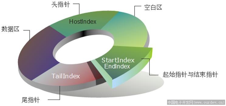
In this way, the blank area and data area of the transmission buffer are dynamically adjusted. The data just sent is immediately opened up for storing the next data, which saves the valuable space of the transmission buffer as much as possible and improves the efficiency.
fifo_buff code
fifo_buff.c
/**
  ******************************************************************************
  * @file       fifo_buff.c/h
  * @brief      Lockless queue
  * @note
  * @history    2021.07.08
  *
  @verbatim
  ==============================================================================
  Using serial +DMA+IDLE interrupt + no lock queue, improve the efficiency of serial port reception (refer to "Osprey official account of SCM")
  1,Once the serial port initialization function is executed, the serial port starts to use DMA to receive data. When an idle interrupt is generated,
    The user can get the data received by DMA cache later.
  2,Because the update of DMA data is determined by the idle interrupt of serial port, once a frame of data is very long
    (If it is greater than 128 or one frame of data is greater than the remaining cache space), the program will find this error,
    And set the flag bit (some errors may not be found), so the cache size setting here is critical,
    Must be greater than one frame cache, preferably more than two frames, and to the power of 2.
  3,If the memory is limited and a larger cache cannot be opened, the DMA half transfer interrupt can be enabled,
    In this way, the DMA cached data can also be retrieved in time (or the method of regular update can be used).
  4,User cache buff_read can be set at will without limitation, but in order to save memory,
    Generally less than or equal to DMA receive cache usart_buff_rx.  In addition, in this example,
    buff_read Data is not cleared and can be cleared on demand.
  5,fifo_read_buff The return value is the actual received data length. If it is equal to 0, it means that no data has been received,
    After reading, the DMA cache data will be automatically cleared,
    The user does not need to clear it (in fact, the cached data is still there, but the user can't read it and will eventually be overwritten by the data received later)
  6,The serial port interrupt can generally be set to the lowest priority because it is automatically received by the DMA background,
    Therefore, the lowest interrupt priority will not lose data (provided that the cache is large enough).
  7,If the serial port is not empty (USART_IT_RXNE) interrupt is used, an ORE error will occur in general reception,
    At this time, if the error is not cleared, it will cause panic, but generally DMA can always receive data in time,
    The error should not occur, but the error flag is also set to find this situation.
  To sum up, the key to serial port reception is DMA cyclic reception and the update of reception index.
  ==============================================================================
  @endverbatim
  ******************************************************************************
  */
#include "fifo_buff.h"
#include <limits.h>

#define IS_POWER_OF_2(x) ((x) != 0 && (((x) & ((x)-1)) == 0))

// Macros are not recommended unless you are sure there are no hidden dangers
// Inline functions are recommended unless you apply min_fifo is very familiar with the scene traps. Otherwise, it is safer to use inline functions, which is also recommended in the Book effective c.
static inline uint32_t min_fifo(uint32_t X, uint32_t Y)
{
    return ((X) > (Y) ? (Y) : (X));
}

/**
  * @brief      Calculate the maximum number that can be rounded to the next second power
  * @param[in]  Num: Number to change
  * @retval     Returns the changed number
  * @attention
  */
uint32_t roundup_pow_of_two(uint32_t Num)
{
    uint32_t result = 1;

    if (IS_POWER_OF_2(Num) || Num == 0)
        return Num;
    else if (Num > LONG_MAX)
        return (LONG_MAX ^ ULONG_MAX); // WARN: if Num is greater than (LONG_MAX+1), the result will be equal to (LONG_MAX+1)

    while (Num)
    {
        Num >>= 1;
        result <<= 1;
    }

    return result;
}

/**
  * @brief          Calculate the smallest fraction that can be rounded to the next power of 2
  * @param[in]      Num: Number to change
  * @retval         Returns the changed number
  * @attention
  */
uint32_t rounddown_pow_of_two(uint32_t Num)
{
    uint32_t result = 1;

    if (IS_POWER_OF_2(Num) || Num == 0)
        return Num;
    else if (Num > LONG_MAX)
        return (LONG_MAX ^ ULONG_MAX); // WARN: if Num is greater than (LONG_MAX+1), the result will be equal to (LONG_MAX+1)

    while (Num)
    {
        Num >>= 1;
        result <<= 1;
    }

    return result >> 1;
}

/**
  * @brief          Initialization of ring buffer
  * @param[in]      pfifo: Initialize circular buffer
  * @param[in]      buff: Ring buffer for storing data
  * @param[in]      size: Buffer size
  * @retval         0 returned successfully
  * @attention
  */
int32_t fifo_init(fifo_rx_def *pfifo, uint8_t *buff, uint32_t size)
{
    assert_param(pfifo != NULL || buff != NULL);

    if (!IS_POWER_OF_2(size)) // Must be to the power of 2
    {
        return -1;
    }

    pfifo->in = 0;
    pfifo->out = 0;
    pfifo->buffer = buff;
    pfifo->size = size; // The size must be set last
    pfifo->last_cnt = size;

    return 0;
}

/**
  * @brief          Get data from ring buffer
  * @param[in]      pfifo: Ring buffer for storing data
  * @param[in]      buffer: The destination buffer that will store data from the circular buffer
  * @param[in]      len: The length to get from the circular buffer
  * @retval         The actual length obtained from the circular buffer
  * @attention
  */
uint32_t fifo_read_buff(fifo_rx_def *pfifo, uint8_t *buffer, uint32_t len)
{
    uint32_t length;

    assert_param(pfifo != NULL || pfifo->buffer != NULL || buffer != NULL);

    len = min_fifo(len, pfifo->in - pfifo->out); //Gets the size from the beginning of the queue out to the end of the array

    /* first get the data from pfifo->out until the end of the buffer */
    length = min_fifo(len, pfifo->size - (pfifo->out & (pfifo->size - 1))); //Gets the size from the beginning of the queue out to the end of the array
    memcpy(buffer, pfifo->buffer + (pfifo->out & (pfifo->size - 1)), length);

    /* then get the rest (if any) from the beginning of the buffer */
    memcpy(buffer + length, pfifo->buffer, len - length);

    pfifo->out += len;

    return len;
}

/**
  * @brief          Put data into ring buffer
  * @param[in]      pfifo: Ring buffer for storing data
  * @param[in]      buffer: The data to be stored in the ring buffer
  * @param[in]      len: The length of data to be stored in the ring buffer
  * @retval         The actual size stored in the ring buffer
  * @attention
  */
uint32_t fifo_write_buff(fifo_rx_def *pfifo, uint8_t *buffer, uint32_t len)
{
    uint32_t length;

    len = min_fifo(len, (pfifo->size - (pfifo->in - pfifo->out)));

    length = min_fifo(len, pfifo->size - (pfifo->in & (pfifo->size - 1)));

    memcpy(pfifo->buffer + (pfifo->in & pfifo->size - 1), buffer, length);
    memcpy(pfifo->buffer, buffer + length, len - length);

    pfifo->in += len;

    return len;
}

/**
  * @brief          Gets the available memory size of the ring buffer
  * @param[in]      pfifo: Ring buffer for storing data
  * @retval         Available memory size of ring buffer
  * @attention
  */
unsigned int fifo_get_free(fifo_rx_def *pfifo)
{
    return ((pfifo->size > 0) ? (pfifo->size - (pfifo->in - pfifo->out)) : 0);
}

/**
  * @brief          Gets the amount of memory used by the ring buffer
  * @param[in]      pfifo: Ring buffer for storing data
  * @retval         The amount of memory used by the ring buffer
  * @attention
  */
unsigned int fifo_get_full(fifo_rx_def *pfifo)
{
    return (pfifo->in - pfifo->out);
}

/**
  * @brief          Check if the ring buffer is empty
  * @param[in]      pfifo: Ring buffer for storing data
  * @retval         If there is no data, return 1
  * @attention
  */
unsigned int fifo_is_empty(fifo_rx_def *pfifo)
{
    return ((pfifo->size > 0) && (pfifo->in == pfifo->out));
}

/**
  * @brief          Check if the ring buffer is full
  * @param[in]      pfifo: Ring buffer for storing data
  * @retval         If full, return 1
  * @attention
  */
unsigned int fifo_is_full(fifo_rx_def *pfifo)
{
    return ((pfifo->size == 0) || (pfifo->size == (pfifo->in - pfifo->out)));
}
fifo_buff.h
/**
  ******************************************************************************
  * @file       nepqiu_fifo_buff.c/h
  * @brief      Lockless queue
  * @note       2021.07.08
  *
  @verbatim
  ==============================================================================
  Using serial +DMA+IDLE interrupt + no lock queue, improve the efficiency of serial port reception (refer to "Osprey official account of SCM")
  1,Once the serial port initialization function is executed, the serial port starts to use DMA to receive data. When an idle interrupt is generated,
    The user can get the data received by DMA cache later.
  2,Because the update of DMA data is determined by the idle interrupt of serial port, once a frame of data is very long
    (If it is greater than 128 or one frame of data is greater than the remaining cache space), the program will find this error,
    And set the flag bit (some errors may not be found), so the cache size setting here is critical,
    Must be greater than one frame cache, preferably more than two frames, and to the power of 2.
  3,If the memory is limited and a larger cache cannot be opened, the DMA half transfer interrupt can be enabled,
    In this way, the DMA cached data can also be retrieved in time (or the method of regular update can be used).
  4,User cache buff_read can be set at will without limitation, but in order to save memory,
    Generally less than or equal to DMA receive cache usart_buff_rx.  In addition, in this example,
    buff_read Data is not cleared and can be cleared on demand.
  5,fifo_read_buff The return value is the actual received data length. If it is equal to 0, it means that no data has been received,
    After reading, the DMA cache data will be automatically cleared,
    The user does not need to clear it (in fact, the cached data is still there, but the user can't read it and will eventually be overwritten by the data received later)
  6,The serial port interrupt can generally be set to the lowest priority because it is automatically received by the DMA background,
    Therefore, the lowest interrupt priority will not lose data (provided that the cache is large enough).
  7,If the serial port is not empty (USART_IT_RXNE) interrupt is used, an ORE error will occur in general reception,
    At this time, if the error is not cleared, it will cause panic, but generally DMA can always receive data in time,
    The error should not occur, but the error flag is also set to find this situation.
  To sum up, the key to serial port reception is DMA cyclic reception and the update of reception index.
  ==============================================================================
  @endverbatim
  ******************************************************************************
  */

#ifndef __NEPQIU_FIFO_BUFF_H__
#define __NEPQIU_FIFO_BUFF_H__
#include <string.h>
#include <stdint.h>
#include "struct_typedef.h"

#define FIFO_ DMA_ ERROR_ RX_ NOT_ Idle (0x1 < < 0) / / non idle interrupt
#define FIFO_ DMA_ ERROR_ RX_ POINT_ Null (0x1 < < 1) / / the pointer is null
#define FIFO_ DMA_ ERROR_ RX_ Full (0x1 < < 2) / / non idle interrupt

typedef struct
{
    uint8_t *buffer;
    uint32_t in;
    uint32_t out;
    uint16_t size;

    uint16_t error; // Receive error
    uint16_t last_cnt;
} fifo_rx_def;


int32_t fifo_init(fifo_rx_def *pfifo, uint8_t *buff, uint32_t size);
uint32_t fifo_read_buff(fifo_rx_def *pfifo, uint8_t *buffer, uint32_t len);
uint32_t fifo_write_buff(fifo_rx_def *pfifo, uint8_t *buffer, uint32_t len);
unsigned int fifo_get_free(fifo_rx_def *pfifo);
unsigned int fifo_get_full(fifo_rx_def *pfifo);
unsigned int fifo_is_empty(fifo_rx_def *pfifo);
unsigned int fifo_is_full(fifo_rx_def *pfifo);

#endif /* __NEPQIU_FIFO_BUFF_H */
Complete code and usage examples
#include "usart1.h"
#include "fifo_buff.h"

#define USART1_IMU_RX_LEN 32
#define USART1_IMU_TX_LEN 32
uint8_t Usart1_IMU_Rx[USART1_IMU_RX_LEN] = {0};
uint8_t Usart1_IMU_Tx[USART1_IMU_TX_LEN] = {0};
uint8_t Usart1_IMU_Tx_Buffer[USART1_IMU_TX_LEN] = {0};

fifo_rx_def fifo_usart_rx_1;
fifo_rx_def *pfifo_1 = &fifo_usart_rx_1;
fifo_rx_def fifo_usart_tx_1;

uint8_t DMA2_Stream7_working = 0;


void usart1_init(void)
{

    /* -------------- Enable Module Clock Source ----------------------------*/
    RCC_AHB1PeriphClockCmd(RCC_AHB1Periph_GPIOA, ENABLE);  //Enable GPIOA clock
    RCC_APB2PeriphClockCmd(RCC_APB2Periph_USART1, ENABLE); //Enable USART1 clock

    GPIO_PinAFConfig(GPIOA, GPIO_PinSource9, GPIO_AF_USART1);  //GPIOA9 multiplexed to USART1
    GPIO_PinAFConfig(GPIOA, GPIO_PinSource10, GPIO_AF_USART1); //GPIOA10 multiplexed to USART1

    /* -------------- Configure GPIO ---------------------------------------*/
    {
        GPIO_InitTypeDef GPIO_InitStruct;
        NVIC_InitTypeDef NVIC_InitStructure;
        USART_InitTypeDef USART1_InitStruct;

        //USART1 port configuration
        GPIO_InitStruct.GPIO_Pin = GPIO_Pin_9 | GPIO_Pin_10; //GPIOA9 and GPIOA10
        GPIO_InitStruct.GPIO_Mode = GPIO_Mode_AF;            //Reuse function
        GPIO_InitStruct.GPIO_Speed = GPIO_Speed_50MHz;       //Speed 50MHz
        GPIO_InitStruct.GPIO_OType = GPIO_OType_PP;          //Push pull multiplex output
        GPIO_InitStruct.GPIO_PuPd = GPIO_PuPd_UP;            //Pull up
        GPIO_Init(GPIOA, &GPIO_InitStruct);                  //Initialize PA9, PA10

        //USART1 initialization settings
        USART_DeInit(USART1);
        USART1_InitStruct.USART_BaudRate = 115200;                                    //Baud rate setting
        USART1_InitStruct.USART_WordLength = USART_WordLength_8b;                     //The word length is in 8-bit data format
        USART1_InitStruct.USART_StopBits = USART_StopBits_1;                          //A stop bit
        USART1_InitStruct.USART_Parity = USART_Parity_No;                             //No parity bit
        USART1_InitStruct.USART_HardwareFlowControl = USART_HardwareFlowControl_None; //No hardware data flow control
        USART1_InitStruct.USART_Mode = USART_Mode_Rx | USART_Mode_Tx;                 //Transceiver mode
        USART_Init(USART1, &USART1_InitStruct);                                       //Initialize serial port 1

        USART_Cmd(USART1, ENABLE); //Enable serial port 1
        USART_ClearFlag(USART1, USART_FLAG_TC);

        //Usart1 NVIC configuration
        NVIC_InitStructure.NVIC_IRQChannel = USART1_IRQn;         //Serial port 1 interrupt channel
        NVIC_InitStructure.NVIC_IRQChannelPreemptionPriority = 1; //Preemption Priority
        NVIC_InitStructure.NVIC_IRQChannelSubPriority = 0;
        NVIC_InitStructure.NVIC_IRQChannelCmd = ENABLE; //IRQ channel enable
        NVIC_Init(&NVIC_InitStructure);                 //Initializes the VIC register according to the specified parameters

        USART_ITConfig(USART1, USART_IT_RXNE, ENABLE); //Turn on related interrupt
        USART_ITConfig(USART1, USART_IT_TC, DISABLE);
        USART_ITConfig(USART1, USART_IT_IDLE, ENABLE);
    }

    /* -------------- Configure DMA -----------------------------------------*/
    /* send out */
    {
        DMA_InitTypeDef DMA_InitStruct;
        NVIC_InitTypeDef NVIC_InitStructure;

        RCC_AHB1PeriphClockCmd(RCC_AHB1Periph_DMA2, ENABLE);

        //send data
        DMA_Cmd(DMA2_Stream7, DISABLE); //Turn off DMA
        DMA_DeInit(DMA2_Stream7);       //Reset to default
        DMA_InitStruct.DMA_Channel = DMA_Channel_4;
        DMA_InitStruct.DMA_PeripheralBaseAddr = (uint32_t) & (USART1->DR);   //source address
        DMA_InitStruct.DMA_Memory0BaseAddr = (uint32_t)(Usart1_IMU_Tx);      //Destination address
        DMA_InitStruct.DMA_DIR = DMA_DIR_MemoryToPeripheral;                 //The data transmission direction is from peripherals to memory
        DMA_InitStruct.DMA_BufferSize = USART1_IMU_TX_LEN;                   //Sets the buffer size of the data
        DMA_InitStruct.DMA_PeripheralInc = DMA_PeripheralInc_Disable;        //The peripheral address remains unchanged
        DMA_InitStruct.DMA_MemoryInc = DMA_MemoryInc_Enable;                 //Memory buffer address self addition
        DMA_InitStruct.DMA_PeripheralDataSize = DMA_PeripheralDataSize_Byte; //8-bit byte transfer
        DMA_InitStruct.DMA_MemoryDataSize = DMA_MemoryDataSize_Byte;         //The data width is 8 bits
        DMA_InitStruct.DMA_Mode = DMA_Mode_Normal;                           //Operating in normal mode
        DMA_InitStruct.DMA_Priority = DMA_Priority_VeryHigh;                 //Highest priority
        DMA_InitStruct.DMA_FIFOMode = DMA_FIFOMode_Disable;
        DMA_InitStruct.DMA_FIFOThreshold = DMA_FIFOThreshold_1QuarterFull;
        DMA_InitStruct.DMA_MemoryBurst = DMA_MemoryBurst_Single;
        DMA_InitStruct.DMA_PeripheralBurst = DMA_PeripheralBurst_Single;
        DMA_Init(DMA2_Stream7, &DMA_InitStruct);

        NVIC_InitStructure.NVIC_IRQChannel = DMA2_Stream7_IRQn;
        NVIC_InitStructure.NVIC_IRQChannelPreemptionPriority = 2;
        NVIC_InitStructure.NVIC_IRQChannelSubPriority = 0;
        NVIC_InitStructure.NVIC_IRQChannelCmd = ENABLE;
        NVIC_Init(&NVIC_InitStructure);

        DMA_ITConfig(DMA2_Stream7, DMA_IT_TC, ENABLE); //Enable send completion interrupt
        DMA_Cmd(DMA2_Stream7, DISABLE);
        USART_DMACmd(USART1, USART_DMAReq_Tx, ENABLE); //Enable DMA transmission of serial port

        if (fifo_init(&fifo_usart_tx_1, Usart1_IMU_Tx_Buffer, USART1_IMU_TX_LEN) == -1)
        {
            // Must be to the power of 2
        }
    }
    // receive data
    {
        DMA_InitTypeDef DMA_InitStruct;

        RCC_AHB1PeriphClockCmd(RCC_AHB1Periph_DMA2, ENABLE);

        DMA_Cmd(DMA2_Stream5, DISABLE); //Turn off DMA
        while (DMA_GetCmdStatus(DMA2_Stream5) != DISABLE)
            ;
        DMA_DeInit(DMA2_Stream5); //Reset to default
        DMA_InitStruct.DMA_Channel = DMA_Channel_4;
        DMA_InitStruct.DMA_PeripheralBaseAddr = (uint32_t) & (USART1->DR);   //source address
        DMA_InitStruct.DMA_Memory0BaseAddr = (uint32_t)(Usart1_IMU_Rx);      //Destination address
        DMA_InitStruct.DMA_DIR = DMA_DIR_PeripheralToMemory;                 //The data transmission direction is from peripherals to memory
        DMA_InitStruct.DMA_BufferSize = USART1_IMU_RX_LEN;                   //Sets the buffer size of the data
        DMA_InitStruct.DMA_PeripheralInc = DMA_PeripheralInc_Disable;        //The peripheral address remains unchanged
        DMA_InitStruct.DMA_MemoryInc = DMA_MemoryInc_Enable;                 //Memory buffer address self addition
        DMA_InitStruct.DMA_PeripheralDataSize = DMA_PeripheralDataSize_Byte; //8-bit byte transfer
        DMA_InitStruct.DMA_MemoryDataSize = DMA_MemoryDataSize_Byte;         //The data width is 8 bits
        DMA_InitStruct.DMA_Mode = DMA_Mode_Circular;                         //Working in circular cache mode
        DMA_InitStruct.DMA_Priority = DMA_Priority_VeryHigh;                 //Highest priority
        DMA_InitStruct.DMA_FIFOMode = DMA_FIFOMode_Disable;
        DMA_InitStruct.DMA_FIFOThreshold = DMA_FIFOThreshold_1QuarterFull;
        DMA_InitStruct.DMA_MemoryBurst = DMA_Mode_Normal; //DMA_MemoryBurst_Single;//
        DMA_InitStruct.DMA_PeripheralBurst = DMA_PeripheralBurst_Single;
        DMA_Init(DMA2_Stream5, &DMA_InitStruct);

        DMA_Cmd(DMA2_Stream5, ENABLE);
        USART_DMACmd(USART1, USART_DMAReq_Rx, ENABLE);

        if (fifo_init(pfifo_1, Usart1_IMU_Rx, USART1_IMU_RX_LEN) == -1)
        {
            // Must be to the power of 2
        }
    }
}

void USART1_IRQHandler(void) // Receive data interrupt
{
    __IO uint8_t Len = 0;

    //Send completion interrupt
    /*
	 * DMA When interrupted, it only means that all data bytes to be transmitted have been transmitted to the transmission data register of the serial port.
	 * At this time, the serial port actually has 2 bytes to send, and the 2 bytes in the data register and shift register need to be sent. The serial port transmission cannot be turned off.
	 * Similarly, if it is 485 switching direction, it must wait until the transmission is completed, that is, the shift register transmission is completed - TC flag is set.
	*/
    if (USART_GetITStatus(USART1, USART_IT_TC) == SET)
    {
        USART_ClearITPendingBit(USART1, USART_IT_TC);
        USART_ITConfig(USART1, USART_IT_TC, DISABLE);
        DMA2_Stream7_working = 0;
    }
    //Bus idle interrupt
    if (USART_GetITStatus(USART1, USART_IT_IDLE) != RESET) //Trigger interrupt flag bit
    {
        Len = USART1->SR;                           //Clear RXNE flag
        Len = USART1->DR;                           //Clear USART_IT_IDLE flag
        Len = DMA_GetCurrDataCounter(DMA2_Stream5); //Function to get the current remaining data size

        if (pfifo_1 != 0)
        {
            // Len is the current receive index
            pfifo_1->in += ((pfifo_1->last_cnt - Len) & (pfifo_1->size - 1)); //Update in
            pfifo_1->last_cnt = Len;

            if ((pfifo_1->in - pfifo_1->out) > pfifo_1->size)
            {
                pfifo_1->out = pfifo_1->in; // Empty the cache and pay attention to the assignment order. Pfifo - > in = pfifo - > out is wrong
                pfifo_1->error |= FIFO_DMA_ERROR_RX_FULL;
            }
        }
        else
        {
            pfifo_1->error |= FIFO_DMA_ERROR_RX_POINT_NULL;
        }
    }
}

/**
  * @brief          Send completion interrupt
  * @param[in]      void
  * @retval         void
  */
/*
 * ST The official has APPNOTE guidance (for the single chip microcomputer model without RS485 function of UART):
 * 1,Before starting DMA, turn off UART transmission completion interrupt and clear the transmission completion interrupt flag;
 * 2,In DMA transmission completion interrupt function, enable UART transmission completion interrupt;
 * 3,In UART transmission completion interrupt function, switch RS485 to receive state;
*/
void DMA2_Stream7_IRQHandler(void)
{
    if (DMA_GetITStatus(DMA2_Stream7, DMA_IT_TCIF7) != RESET)
    {
        DMA_ClearFlag(DMA2_Stream7, DMA_IT_TCIF7);
        DMA_Cmd(DMA2_Stream7, DISABLE); //Disable transmission
        //while (DMA_GetCmdStatus(DMA2_Stream7) != DISABLE);
        USART_ITConfig(USART1, USART_IT_TC, ENABLE);

        //DMA2_Stream7_working = 0;
    }
}

/**
  * @brief          Serial port 1 + DMA transmission
  * @param[in]      *data
  * @param[in]      len
  * @retval         void
  */
uint32_t usart1_dma_send(uint8_t *data, uint16_t len)
{
    uint32_t result = fifo_write_buff(&fifo_usart_tx_1, data, len); //Put data into circular buffer

    //result != 0 indicates that the data is successfully put into DMA2_Stream6_working == 0 indicates that there is no data in the buffer
    if (DMA2_Stream7_working == 0 && result != 0)
    {
        len = fifo_read_buff(&fifo_usart_tx_1, Usart1_IMU_Tx, USART1_IMU_TX_LEN); //Get data from circular buffer

        DMA_SetCurrDataCounter(DMA2_Stream7, len); //Set transmission length
        DMA_Cmd(DMA2_Stream7, ENABLE);             //Enable transmission

        DMA2_Stream7_working = 1;
    }

    if (result == len)
    {
        return len;
    }
    else
    {
        return result;
    }
}
No matter what data is used to receive, the same configuration can be used. Only usart1 needs to be changed_ IMU_ RX_ Len and USART1_IMU_TX_LEN these two macros
Loop only where needed
extern fifo_rx_def fifo_usart_rx_1;
fifo_rx_def *pfifo_x = &fifo_usart_rx_1;

void usart_data_receive(void)
{
	uint8_t buff_read[32];

	uint32_t length = fifo_read_buff(pfifo_x, buff_read, 32);
    if (length)
    {
        //printf("lengtt = %d", length); //  Actual received data length
	}
	else
	{
		//no data
	}

	if (pfifo_x->error)
    {
		// Receive error
        pfifo_x->error = 0;
    }
}
To replace the serial port is also very simple, you only need to
extern fifo_rx_def fifo_usart_rx_1;
fifo_rx_def *pfifo_x = &fifo_usart_rx_1;
Change to the corresponding serial port, such as serial port 2
extern fifo_rx_def fifo_usart_rx_2;
fifo_rx_def *pfifo_x = &fifo_usart_rx_2;
The remaining configurations are exactly the same