STM32 - external interrupt configuration
Overall diagram of external interrupt configuration:
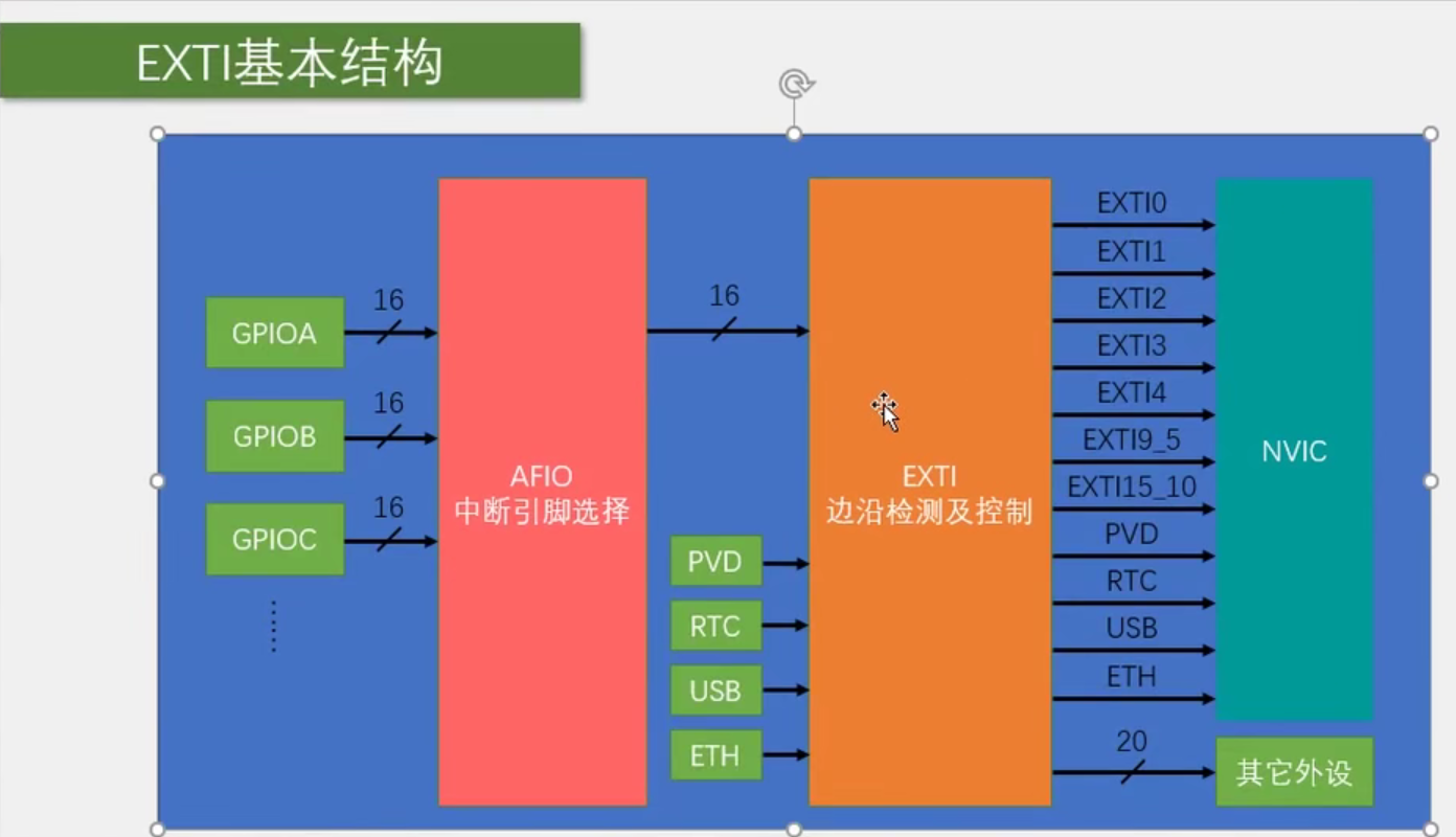
The steps are as follows:
- Configure RCC and turn on the clocks of the peripherals involved here. There is no way to work without turning on the clock peripherals.
- Configure GPIO and select our port as the input mode.
- Configure AFIO, select the GPIO we use, and connect it to the EXIT.
- Configure EXTI and select edge trigger mode, such as rising edge, falling edge or bilateral edge. In addition, you can select the trigger response mode, including interrupt response and event response. Here we generally refer to interrupt response.
- Configure NVIC and select an appropriate priority for our interrupts. Finally, through the NVIC, the external interrupt signal can enter the CPU.
- Finally, find the corresponding interrupt function.
Here are the specific steps for each step:
- Configure RCC
- Configure the clock of GPIOB
RCC_APB2PeriphClockCmd (RCC_APB2Periph_GPIOB,ENABLE);
- Configure the clock of AFIO
RCC_APB2PeriphClockCmd (RCC_APB2Periph_AFIO,ENABLE);
- Both EXTI and NVIC do not need to turn on the clock, because these two are peripherals of the kernel. Peripherals of the kernel do not need to turn on the clock, which is equivalent to living in the "Palace" with the CPU. RCC manages peripherals outside the kernel, so it can't manage NVIC.
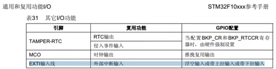
- Both here and are familiar with configuring GPIO. Here, according to the recommendation of ST company's manual, configure the corresponding mode corresponding to exi.
    GPIO_InitTypeDef GPIO_InitStructure;//Name the enumeration type structure GPIO_InitStructure
    GPIO_InitStructure.GPIO_Mode = GPIO_Mode_IPU;//Because EXTI is used here, it is recommended to configure it as pull-up input according to the manual.
    GPIO_InitStructure.GPIO_Pin = GPIO_Pin_14;
    GPIO_InitStructure.GPIO_Speed =GPIO_Speed_50MHz;
    GPIO_Init (GPIOB,&GPIO_InitStructure);
- Configure AFIO
    //AFIO configuration
    GPIO_EXTILineConfig (GPIO_PortSourceGPIOB,GPIO_PinSource14);
This statement is equivalent to connecting the 14th i\o port of GPIOB with the 14th external interrupt line of EXTI.
- Configure EXTI
    EXTI_InitTypeDef  EXTI_InitStructure;
    EXTI_InitStructure.EXTI_Line = EXTI_Line14; //Configure the fourteenth interrupt line
    EXTI_InitStructure.EXTI_LineCmd = ENABLE;  //Enable EXTI
    EXTI_InitStructure.EXTI_Mode = EXTI_Mode_Interrupt; // Use interrupt mode
    EXTI_InitStructure.EXTI_Trigger = EXTI_Trigger_Falling;  //Falling edge trigger
    EXTI_Init(&EXTI_InitStructure);
- Configure NVIC
    NVIC_PriorityGroupConfig(NVIC_PriorityGroup_2);//Only one grouping method can be used for each chip, so the code can only appear once. It is recommended to put it at the beginning of the main () function.
    NVIC_InitTypeDef NVIC_InitStructure;
    NVIC_InitStructure.NVIC_IRQChannel =EXTI15_10_IRQn;//EXTI10 to EXTI15 in STM32 are merged into this channel.
    NVIC_InitStructure.NVIC_IRQChannelCmd=ENABLE;
    NVIC_InitStructure.NVIC_IRQChannelPreemptionPriority=1;
    NVIC_InitStructure.NVIC_IRQChannelSubPriority=1;
    NVIC_Init(&NVIC_InitStructure);
- Configure the corresponding interrupt function. To find the interrupt function corresponding to the corresponding interrupt channel, go to the startup file in the STM32 library function (startup_stm32f10x_md.s)
    void EXTI15_10_IRQHandler(void)
    {
        if(EXTI_GetITStatus(EXTI_Line14)== SET)//Judge whether it is the interrupt function from interrupt port 14.
        {
            /*

            Here write the program to be executed by the interrupt function

            */
            EXTI_ClearITPendingBit(EXTI_Line14);//Clear the interrupt flag bit. If it is not clear, the program will always be stuck in the interrupt program.
        }
    }
Finally, remember to clear the interrupt flag bit after the execution of the interrupt program.
All programs
#include "stm32f10x.h"                  // Device header

void Countsensor_Init(void)
{
    //Configuration of GPIO
    GPIO_InitTypeDef GPIO_InitStructure;//Name the enumeration type structure GPIO_InitStructure
    GPIO_InitStructure.GPIO_Mode = GPIO_Mode_IPU;//Because EXTI is used here, we recommend to configure it as pull-up input according to the manual.
    GPIO_InitStructure.GPIO_Pin = GPIO_Pin_14;
    GPIO_InitStructure.GPIO_Speed =GPIO_Speed_50MHz;
    GPIO_Init (GPIOB,&GPIO_InitStructure);

    //Clock configuration
    RCC_APB2PeriphClockCmd (RCC_APB2Periph_GPIOB,ENABLE);
    RCC_APB2PeriphClockCmd (RCC_APB2Periph_AFIO,ENABLE);

    //AFIO configuration
    GPIO_EXTILineConfig (GPIO_PortSourceGPIOB,GPIO_PinSource14);

    //Configure EXTI
    EXTI_InitTypeDef EXTI_InitStructure;
    EXTI_InitStructure.EXTI_Line = EXTI_Line14; //Configure the fourteenth interrupt line
    EXTI_InitStructure.EXTI_LineCmd = ENABLE;  //Enable EXTI
    EXTI_InitStructure.EXTI_Mode = EXTI_Mode_Interrupt; // Use interrupt mode
    EXTI_InitStructure.EXTI_Trigger = EXTI_Trigger_Falling;  //Falling edge trigger
    EXTI_Init(&EXTI_InitStructure);

    //Configure NVIC
    NVIC_PriorityGroupConfig(NVIC_PriorityGroup_2);//Only one grouping method can be used for each chip, so the code can only appear once. It is recommended to put it at the beginning of the main () function.
    NVIC_InitTypeDef NVIC_InitStructure;
    NVIC_InitStructure.NVIC_IRQChannel =EXTI15_10_IRQn;//EXTI10 to EXTI15 in STM32 are merged into this channel.
    NVIC_InitStructure.NVIC_IRQChannelCmd=ENABLE;
    NVIC_InitStructure.NVIC_IRQChannelPreemptionPriority=1;
    NVIC_InitStructure.NVIC_IRQChannelSubPriority=1;
    NVIC_Init(&NVIC_InitStructure);

}
void EXTI15_10_IRQHandler(void)
    {
        if(EXTI_GetITStatus(EXTI_Line14)== SET)//Judge whether it is the interrupt function from interrupt port 14.
        {
            /*

            Here write the program to be executed by the interrupt function

            */
            EXTI_ClearITPendingBit(EXTI_Line14);//Clear the interrupt flag bit. If it is not clear, the program will always be stuck in the interrupt program.
        }
    }
Statement: This article is written with reference to the video of the Automation Association of the University of science and technology at station b, that is, the learning notes.