1 overview of external interrupts
EXTI (External interrupt/event controller) - External interrupt/event controller, which is different from the external interrupt of CM3 kernel described in STM32NVIC interrupt priority management (interrupt vector table). Specifically, the external interrupt of EXTI in the interrupt vector table. Each IO of STM32 can be used as an external interrupt input. EXTI manages 20 interrupt / event lines of the controller. Each interrupt / event line corresponds to an edge detector, which can detect the rising edge and falling edge of the input signal. EXTI can configure each interrupt / event line separately, as an interrupt or event, and the attributes of the trigger event.
one point one External interrupt line
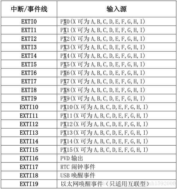
The interrupt controller of STM32 supports 19 external interrupts and event requests (that is, 19 external interrupt lines). Each interrupt is equipped with status bits, and each interrupt / event has independent trigger and mask settings. The 19 external interrupts of STM32 correspond to 19 medium break lines, which are exti respectively_ Line0-EXTI_ Line18: :
Line 0 ~ 15: input interrupt corresponding to external IO port;
Line 16: connected to PVD output;
Line 17: connected to RTC alarm clock event;
Line 18: connect to USB wake-up event.
The functional block diagram of external interrupt contains the core content of external interrupt. If you master the functional block diagram, you will have an overall grasp of external interrupt, and the idea is very clear when programming. The block diagram of external interrupt function is shown in figure.
It can be seen in the figure that many signal lines are marked with a slash and marked with "20". This indicates that there are 20 similar signal lines in the controller, which is consistent with a total of 20 interrupt / event lines for external interrupts. So as long as we understand the principle of one of them, we will know the principle of the other 19 lines.
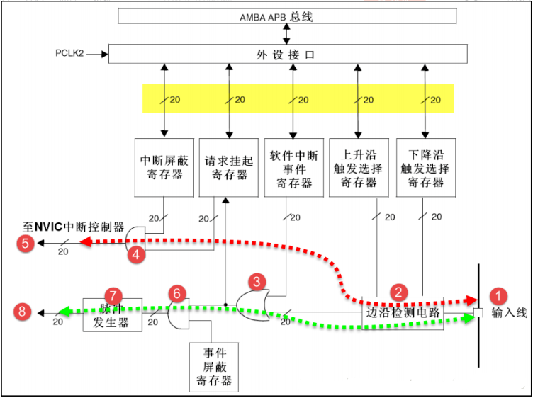
External interrupt can be divided into two major functions, one is to generate interrupt and the other is to generate event. These two functions are different in hardware.
First, let's look at the circuit flow indicated by the red dotted line in the figure. It is a line that generates an interrupt, and the final signal flows into the NVIC controller.
No. 1 is the input line. The external interrupt controller has 19 interrupt / event input lines. These input lines can be set to any GPIO or some peripheral events through the register. We will explain this part later. The input line is generally a signal with level change.
No. 2 is an edge detection circuit, which controls signal triggering according to the setting of corresponding bits of rising edge trigger selection register (EXTI_RTSR) and falling edge trigger selection register (EXTI_FTSR). The edge detection circuit takes the input line as the signal input. If an edge jump is detected, it outputs an effective signal 1 to the No. 3 circuit, otherwise it outputs an invalid signal 0. And exti_ RTSR and exti_ The two registers of FTSR can determine which types of level jump process the controller needs to detect, which can be triggered by only the rising edge, only the falling edge, or both the rising edge and the falling edge.
The No. 3 circuit is actually an OR gate circuit. One input comes from the No. 2 circuit and the other input comes from the software interrupt event register (EXTI_SWIER). EXTI_ Swier allows us to start interrupt / event lines through program control, which is very useful in some places. We know that the function of or gate is that if there is 1, it is 1, so if either of these two inputs has a valid signal 1, it can output 1 to circuits No. 4 and No. 6.
The No. 4 circuit is an and gate circuit. One input is the No. 3 circuit and the other input is from the interrupt mask register (EXTI_IMR). The and gate circuit requires both inputs to be 1 before outputting 1. The result is if exti_ When IMR is set to 0, no matter whether the output signal of No. 3 circuit is 1 or 0, the final output signal of No. 4 circuit is 0; If exti_ When IMR is set to 1, the output signal of the final No. 4 circuit is determined by the output signal of the No. 3 circuit, so that we can simply control exti_ IMR to achieve the purpose of whether to generate interrupt. The signal output by the No. 4 circuit will be saved in the hold register (EXTI_PR). If it is determined that the output of the No. 4 circuit is 1, it will put exti_ PR corresponds to position 1.
No. 5 is exti_ The contents of PR register are output to NVIC to realize system interrupt event control.
Next, let's look at the circuit flow indicated by the green dotted line. It is a circuit that generates events and finally outputs a pulse signal.
The event line is different from the interrupt line after the No. 3 circuit, and the previous circuits are common.
The No. 6 circuit is an and gate circuit with one input from the No. 3 circuit and the other input from the event mask register (EXTI_EMR). If exti_ When EMR is set to 0, no matter whether the output signal of No. 3 circuit is 1 or 0, the signal output by the final No. 6 circuit is 0; If exti_ When EMR is set to 1, the final output signal of circuit No. 6 is determined by the output signal of circuit No. 3, so we can simply control exti_ EMR to achieve whether to generate
The purpose of the event.
No. 7 is a pulse generator circuit. When its input, that is, the output of No. 6 circuit, is a valid signal 1, a pulse will be generated; If the input is an invalid signal, no pulse will be output.
No. 8 is a pulse signal, which is the final product of the line generating the event. This pulse signal can be used for other peripheral circuits, such as timer TIM, analog-to-digital converter ADC, etc. such pulse signal is generally used to trigger TIM or ADC to start conversion.
The purpose of generating interrupt line is to input the input signal to NVIC, and further run the interrupt service function to realize the function, which is software level. The purpose of generating event line is to transmit a pulse signal to other peripherals, and it is circuit level signal transmission, which belongs to hardware level.
In addition, EXTI is on APB2 bus, which should be noted during programming.
Each external interrupt line can be independently configured with trigger mode (rising edge, falling edge or bilateral edge trigger), enable / disable interrupt and special status bit.
There are 20 interrupt / event lines for external interrupts. Each GPIO can be set as an input line, occupying EXTI0 to EXTI15. There are four other lines for specific peripheral events. It can be seen that there are only 16 interrupt lines for IO in STM32, but there are hundreds of IO ports in STM32F10x series, of which STM32F103ZET6 has 112 pins (7 groups of GPIO, 16 in each group). So how does the interrupt line correspond to the IO port?
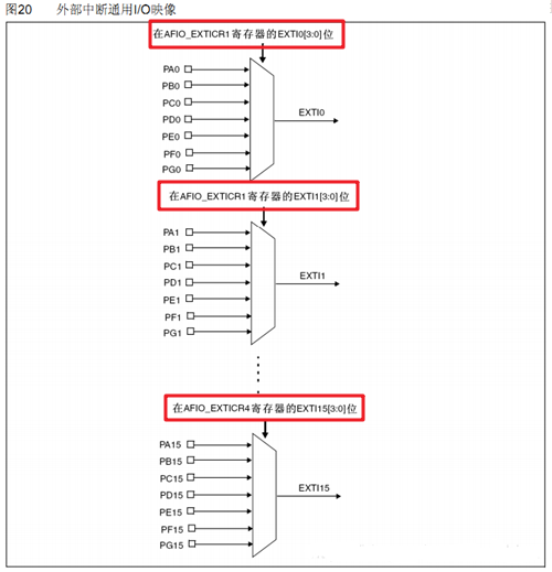
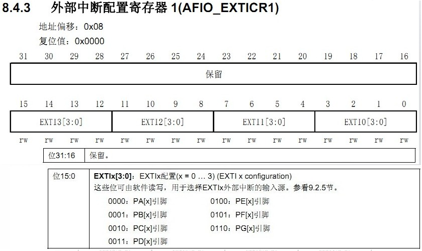
It can be easily seen from the above figure that the same number of pins (7 in total) of each GPIOx corresponds to a broken wire. For example, PA0, PB0, PC0, PD0, PE0, PF0 and PG0 are broken. EXTI0 to EXTI15 are used for GPIO. Any GPIO can be used as the input source of external interrupt through programming control. It can be seen from the table that EXTI0 can be selected and configured as PA0, PB0, PC0, PD0, PE0, PF0 and PG0 through the EXTI0[3:0] bit of AFIO external interrupt configuration register 1(AFIO_EXTICR1). The use configuration of other EXTI lines (EXTI interrupt / event lines) is similar.
Note: only one IO port can be mapped to the same interrupt line at the same time. That is, PA0 and PB0 cannot be mapped to the same interrupt line at the same time, while PA0 and PA1 can be mapped at the same time because they are not on the same interrupt line.
one point two Interrupt service function
Can 16 interrupt service functions be allocated to 16 interrupt lines?
Neither is the answer. Previously, in the STM32NVIC interrupt priority management article, we introduced the interrupt vector table. In the interrupt vector table, only 7 interrupt vectors are allocated to the external interrupt of IO port in the interrupt vector table, that is, only 7 interrupt service functions can be used.
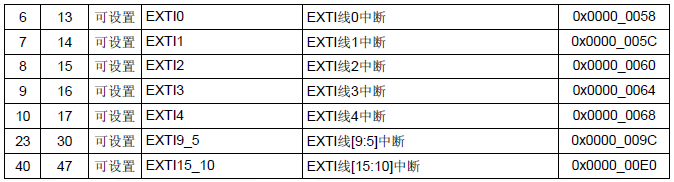
As can be seen from the above figure, the external interrupt lines 5 ~ 9 allocate an interrupt vector and share a service function; The external interrupt lines 10 ~ 15 allocate an interrupt vector and share an interrupt service function; Interrupt vector lines 0-4 use an interrupt service function alone. In other words, the maximum number of external interrupts of the IO port can be 7.
Mapping relationship of interrupt service function:
| GPIO | IRQn | IRQHandler |
| GPIO_Pin0 | EXTI0_IRQn | EXTI0_IRQHandler |
| GPIO_Pin1 | EXTI1_IRQn | EXTI1_IRQHandler |
| GPIO_Pin2 | EXTI2_IRQn | EXTI2_IRQHandler |
| GPIO_Pin3 | EXTI3_IRQn | EXTI3_IRQHandler |
| GPIO_Pin4 | EXTI4_IRQn | EXTI4_IRQHandler |
| GPIO_Pin5 — GPIO_Pin9 | EXTI9_5_IRQn | EXTI9_5_IRQHandler |
| GPIO_Pin10 — GPIO_Pin15 | EXTI15_10_IRQn | EXTI15_10_IRQHandler |
The following lists the names of the interrupt service functions (on the startup file startup_stm32f10x_hd.s):
void EXTI0_IRQHandler()
void EXTI1_IRQHandler()
void EXTI2_IRQHandler()
void EXTI3_IRQHandler()
void EXTI4_IRQHandler()
void EXTI9_5_IRQHandler()
void EXTI15_10_IRQHandler()
two External interrupt related configuration register
two point one Interrupt mask register (EXTI_IMR)
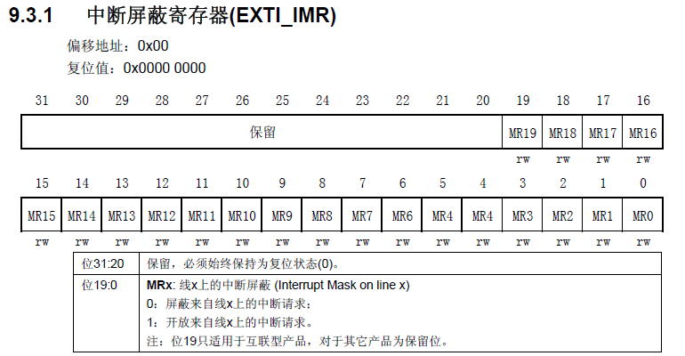
Function: each bit corresponds to a broken line. Clearing indicates that the interrupt request on the line is shielded; Set to 1 to open the interrupt request on the line. This is a 32 register. But only the first 19 are valid. When bit x is set to 1, the interrupt on this line is turned on, otherwise the interrupt on this line is turned off.
two point two Event mask register (EXTI_EMR)
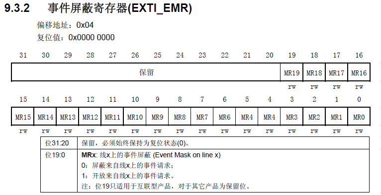
Function: each bit corresponds to a broken line. Clearing indicates that the event request on the line is shielded; Set to 1 to open the event request on the line. The same as IMR, but this register is for event masking and opening.
2.3 rising edge trigger selection register (EXTI_RTSR)
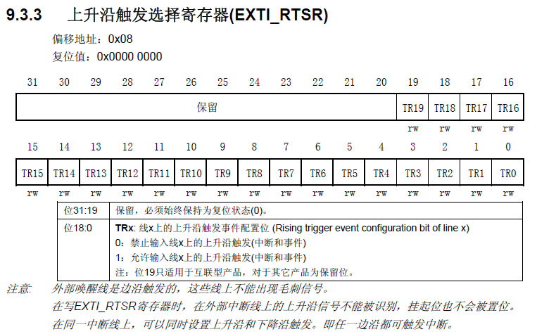
Function: each bit corresponds to a broken line. Clearing to zero means that the rising edge of closing triggers an interrupt or event; Set to 1 to open the rising edge to trigger an interrupt or event. This register, like the IMR, is also a 32 bit register, and only the first 19 bits are valid. Bit x corresponds to the rising edge trigger on line X. if it is set to 1, the rising edge is allowed to trigger interrupt / event. Otherwise, it is not allowed.
two point four Falling edge trigger selection register (EXTI_FTSR)
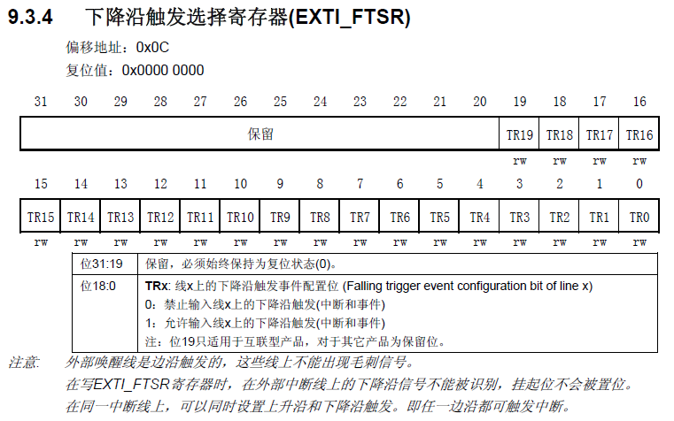
Function: each bit corresponds to a broken line. Clearing to zero means closing the falling edge to trigger an interrupt or event; Set to 1 to open the falling edge to trigger an interrupt or event. The same as PTSR, but this register sets the falling edge. The falling edge and rising edge can be set at the same time, which becomes an arbitrary level trigger.
two point five Software trigger event register (EXTI_SWIER)
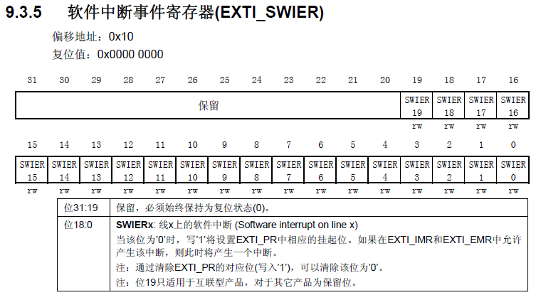
Function: each bit corresponds to a broken line. When EXTIx interrupt is valid and SWIER=0, writing 1 to SWIER will trigger the interrupt request. By writing 1 to bit x of the register, when IMR and EMR are not set, the corresponding bit in PR is suspended. If IMR and EMR are set, an interrupt will be generated. The SWIER bit set will be cleared after the corresponding bit in PR is cleared.
two point six Suspend register (EXTI_PR)
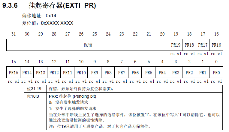
Function: each bit corresponds to a broken line. If the ith interrupt is triggered, the corresponding bit of PR bit is automatically set to 1; Write 1 to the PR bit, clear the bit, and clear the SWIER bit at the same time. 0 indicates that there is no trigger request on the corresponding line. 1 indicates that the selected edge event has occurred on the external interrupt line. This bit can be cleared by writing 1 to the corresponding bit of the register. In the interrupt service function, it is often necessary to write 1 to the corresponding bit of the register to clear the interrupt request.
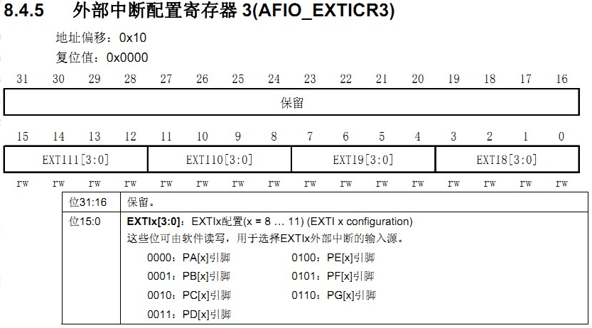
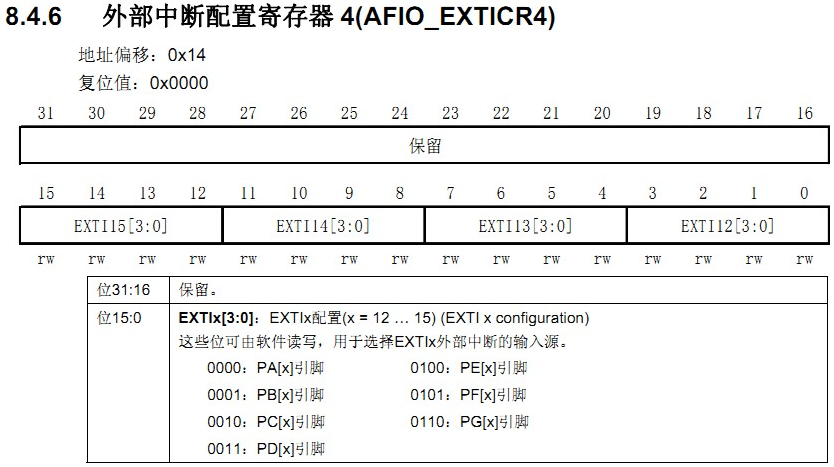
two point seven EXTICR register group (EXTICR[0]~ EXTICR[3])
There are four EXTICR register groups in total. Because the register groups of the compiler are numbered from 0, EXTICR[0]~ EXTICR[3] correspond to EXTICR1~ EXTICR 4 in STM32 reference manual (it took a long time to understand the meaning of this array!!). Each exicr uses only its lower 16 bits.
The assignment of EXTICR[0] ~EXTICR[3] is as follows:

3 external interrupt configuration related library functions
three point one 1 mapping function
void GPIO_EXTILineConfig(uint8_t GPIO_PortSource, uint8_t GPIO_PinSource);
Function: set the mapping relationship between IO port and interrupt line.
three point two 1 initialization function
void EXTI_Init(EXTI_InitTypeDef* EXTI_InitStruct);
Function: initialize interrupt line, set trigger mode, interrupt or event, etc.
three point three 2 flag bit functions
ITStatus EXTI_GetITStatus(uint32_t EXTI_Line);
void EXTI_ClearITPendingBit(uint32_t EXTI_Line);
Function: the former determines the interrupt status of the interrupt line and whether it occurs; The latter clears the interrupt flag bit on the interrupt line.
In fact, in addition to these two flag bit functions, the firmware library also provides two functions to judge the external interrupt state and clear the Aibu state flag bit, respectively:
FlagStatus EXTI_GetFlagStatus(uint32_t EXTI_Line);
void EXTI_ClearFlag(uint32_t EXTI_Line);
Their functions are similar to those of the previous two functions, except in exti_ In the getitstatus() function, it will first judge whether this interrupt is enabled, and then judge the interrupt flag bit, and EXTI_GetFlagStatus directly determines the status flag bit.
four External interrupt general steps
1) Turn on the clock of IO port and initialize IO port as input. Calling function: GPIO_Init();
2) Turn on the IO port multiplexing clock. Calling function: RCC_APB2PeriphClockCmd(RCC_APB2Periph_AFIO,ENABLE);
3) Set the mapping relationship between IO port and interrupt line. Calling function: GPIO_EXTILineConfig();
4) Initialize online interrupt, set trigger conditions, etc. Calling function: EXTI_Init();
5) Configure interrupt packet (NVIC) and enable interrupts. Calling function: NVIC_Init();
6) Write an interrupt service function. Calling function: EXTIx_IRQHandler();
7) Clear the interrupt flag bit. Calling function: EXTI_ClearITPendingBit().
Follow this general procedure to perform a simple external interrupt program:
void KEY_Init(void) //IO initialization
{
 	GPIO_InitTypeDef GPIO_InitStructure;

    //Enable PORTA,PORTE clock
 	RCC_APB2PeriphClockCmd(RCC_APB2Periph_GPIOA|RCC_APB2Periph_GPIOE,ENABLE);

    //Initialize GPIO mode and corresponding pins
	GPIO_InitStructure.GPIO_Pin  = GPIO_Pin_2|GPIO_Pin_3|GPIO_Pin_4;//KEY0-KEY2
	GPIO_InitStructure.GPIO_Mode = GPIO_Mode_IPU; //Set as pull-up input
 	GPIO_Init(GPIOE, &GPIO_InitStructure);//Initialize GPIOE2,3,4

	//Initialize wk_ UP-->GPIOA.0 	   Drop down input
	GPIO_InitStructure.GPIO_Pin  = GPIO_Pin_0;
	GPIO_InitStructure.GPIO_Mode = GPIO_Mode_IPD; //PA0 is set as input, and the default is drop-down
	GPIO_Init(GPIOA, &GPIO_InitStructure);//Initialize GPIOA.0

}
void EXTIX_Init(void)
{
EXTI_InitTypeDef EXTI_InitStructure;
NVIC_InitTypeDef NVIC_InitStructure;
//Key port initialization
KEY_Init();
//Enable multiplexing function clock
RCC_APB2PeriphClockCmd(RCC_APB2Periph_AFIO,ENABLE);
//The falling edge of disconnection and interrupt initialization configuration in GPIOE.2 is triggered
//Select EXTI signal source
GPIO_EXTILineConfig(GPIO_PortSourceGPIOE,GPIO_PinSource2);
//Determine the medium break, interrupt mode, trigger mode and enable:
EXTI_InitStructure.EXTI_Line=EXTI_Line2; //KEY2
EXTI_InitStructure.EXTI_Mode = EXTI_Mode_Interrupt;
EXTI_InitStructure.EXTI_Trigger = EXTI_Trigger_Falling;
EXTI_InitStructure.EXTI_LineCmd = ENABLE;
EXTI_Init(&EXTI_InitStructure); //According to EXTI_ Initialize the peripheral EXTI register with the parameters specified in initstruct
//GPIOE.3 Interrupt line and falling edge of interrupt initialization configuration trigger / / KEY1
//Select EXTI signal source
GPIO_EXTILineConfig(GPIO_PortSourceGPIOE,GPIO_PinSource3);
//Determine the medium break, interrupt mode, trigger mode and enable:
EXTI_InitStructure.EXTI_Line=EXTI_Line3;
EXTI_Init(&EXTI_InitStructure); //According to EXTI_ Initialize the peripheral EXTI register with the parameters specified in initstruct
//GPIOE.4 The interrupt line and the falling edge of interrupt initialization configuration are triggered // KEY0
//Select EXTI signal source
GPIO_EXTILineConfig(GPIO_PortSourceGPIOE,GPIO_PinSource4);
//Determine the medium break, interrupt mode, trigger mode and enable:
EXTI_InitStructure.EXTI_Line=EXTI_Line4;
EXTI_Init(&EXTI_InitStructure); //According to EXTI_ Initialize the peripheral EXTI register with the parameters specified in initstruct
//GPIOA.0 The rising edge of interrupt line and interrupt initialization configuration triggers PA0 wk_ UP
//Select EXTI signal source
GPIO_EXTILineConfig(GPIO_PortSourceGPIOA,GPIO_PinSource0);
//Determine the medium break, interrupt mode, trigger mode and enable:
EXTI_InitStructure.EXTI_Line=EXTI_Line0;
EXTI_InitStructure.EXTI_Trigger = EXTI_Trigger_Rising;
EXTI_Init(&EXTI_InitStructure); //According to EXTI_ Initialize the peripheral EXTI register with the parameters specified in initstruct
//Determine the interrupt source and priority (preemptive priority and sub priority) to enable:
NVIC_InitStructure.NVIC_IRQChannel = EXTI0_IRQn; //Enable key wk_ External interrupt channel where up is located
NVIC_InitStructure.NVIC_IRQChannelPreemptionPriority = 0x02; //Preemption priority 2,
NVIC_InitStructure.NVIC_IRQChannelSubPriority = 0x03; //Sub priority 3
NVIC_InitStructure.NVIC_IRQChannelCmd = ENABLE; //Enable external interrupt channel
NVIC_Init(&NVIC_InitStructure);
//Determine the interrupt source and priority (preemptive priority and sub priority) to enable:
NVIC_InitStructure.NVIC_IRQChannel = EXTI2_IRQn; //Enable the external interrupt channel where the key KEY2 is located
NVIC_InitStructure.NVIC_IRQChannelPreemptionPriority = 0x02; //Preemption priority 2,
NVIC_InitStructure.NVIC_IRQChannelSubPriority = 0x02; //Sub priority 2
NVIC_InitStructure.NVIC_IRQChannelCmd = ENABLE; //Enable external interrupt channel
NVIC_Init(&NVIC_InitStructure);
//Determine the interrupt source and priority (preemptive priority and sub priority) to enable:
NVIC_InitStructure.NVIC_IRQChannel = EXTI3_IRQn; //Enable the external interrupt channel where key 1 is located
NVIC_InitStructure.NVIC_IRQChannelPreemptionPriority = 0x02; //Preemption priority 2
NVIC_InitStructure.NVIC_IRQChannelSubPriority = 0x01; //Sub priority 1
NVIC_InitStructure.NVIC_IRQChannelCmd = ENABLE; //Enable external interrupt channel
NVIC_Init(&NVIC_InitStructure); //According to NVIC_ Initializes the peripheral NVIC register with the parameters specified in initstruct
//Determine the interrupt source and priority (preemptive priority and sub priority) to enable:
NVIC_InitStructure.NVIC_IRQChannel = EXTI4_IRQn; //Enable the external interrupt channel where the key KEY0 is located
NVIC_InitStructure.NVIC_IRQChannelPreemptionPriority = 0x02; //Preemption priority 2
NVIC_InitStructure.NVIC_IRQChannelSubPriority = 0x00; //Sub priority 0
NVIC_InitStructure.NVIC_IRQChannelCmd = ENABLE; //Enable external interrupt channel
NVIC_Init(&NVIC_InitStructure); //According to NVIC_ Initializes the peripheral NVIC register with the parameters specified in initstruct
}
//External interrupt 0 service routine
void EXTI0_IRQHandler(void)
{
delay_ms(10);//Debounce
if(WK_UP==1) //WK_UP button
{
BEEP=!BEEP;
}
EXTI_ClearITPendingBit(EXTI_Line0); //Clear the interrupt flag bit on LINE0
}
//External interrupt 2 service program
void EXTI2_IRQHandler(void)
{
delay_ms(10);//Debounce
if(KEY2==0) //Key KEY2
{
LED0=!LED0;
}
EXTI_ClearITPendingBit(EXTI_Line2); //Clear the interrupt flag bit on LINE2
}
//External interrupt 3 service routine
void EXTI3_IRQHandler(void)
{
delay_ms(10);//Debounce
if(KEY1==0) //Key 1
{
LED1=!LED1;
}
EXTI_ClearITPendingBit(EXTI_Line3); //Clear the interrupt flag bit on LINE3
}
void EXTI4_IRQHandler(void)
{
delay_ms(10);//Debounce
if(KEY0==0) //Key KEY0
{
LED0=!LED0;
LED1=!LED1;
}
EXTI_ClearITPendingBit(EXTI_Line4); //Clear the interrupt flag bit on LINE4
} EXTIX_Init function
1)RCC_APB2PeriphClockCmd(RCC_APB2Periph_AFIO,ENABLE) enables multiplexing of function clocks. This step cannot be omitted, otherwise there will be problems. STM32 port multiplexing and remapping (AFIO auxiliary function clock)
2) In the process of writing interrupt processing function, in the last step, you must remember to clear the interrupt flag bit. Calling function: EXTI_ClearITPendingBit(). Otherwise, the next interrupt will not occur.
Here, we configure two interrupt software with the same priority. What if two keys are pressed at the same time? Which interrupt should be executed? When the software priority of two interrupts is the same, when an interrupt comes, which interrupt service function to execute first is determined by the interrupt number of the hardware. The smaller the number, the higher the priority. For the hardware number of peripherals, you can query the vector table in the interrupt and event section of STM32F10X Chinese reference manual. The position number in the table is the hardware interrupt priority of each peripheral. Of course, we can also set the preemption priority to the same and the sub priority to different. In this way, we can distinguish the case where two keys are pressed at the same time without comparing the hardware number with the hardware number.
GPIO_EXTILineConfig(uint8_t GPIO_PortSource, uint8_t GPIO_PinSource); Used to select GPIO pin as external interrupt line. This is defined in the Library:
/**
 * @Select the GPIO pin for the EXTI line.
 * @Parameter GPIO_PortSource: select GPIO port as the source of EXTI line.
 *   This parameter can be GPIO_PortSourceGPIOx, x can be (A..G).
 * @Parameter GPIO_PinSource: Specifies the EXTI line to configure.
 *   This parameter can be GPIO_PinSourcex, where x can be (0.. 15).
 * @Return value none
  */
void GPIO_EXTILineConfig(uint8_t GPIO_PortSource, uint8_t GPIO_PinSource)
{
  uint32_t tmp = 0x00;
  /* Check parameters */
  assert_param(IS_GPIO_EXTI_PORT_SOURCE(GPIO_PortSource));
  assert_param(IS_GPIO_PIN_SOURCE(GPIO_PinSource));

  tmp = ((uint32_t)0x0F) << (0x04 * (GPIO_PinSource & (uint8_t)0x03));
  AFIO->EXTICR[GPIO_PinSource >> 0x02] &= ~tmp;
  AFIO->EXTICR[GPIO_PinSource >> 0x02] |= (((uint32_t)GPIO_PortSource) << (0x04 * (GPIO_PinSource & (uint8_t)0x03)));
}