The notes of the article are from the video of the Automation Association of Jiangke University
I Interrupt system
Interrupt: during the operation of the main program, a specific interrupt trigger condition occurs, causing the CPU to suspend the currently running program and process the interrupt program. After completion, it returns to the original suspended position to continue working
Interrupt priority: when multiple interrupts start, the CPU will respond to more urgent interrupts according to the severity of things
Interrupt nesting: when an interrupt is normal and another higher-level interrupt comes, it will first do the first high-level interrupt and then return in turn
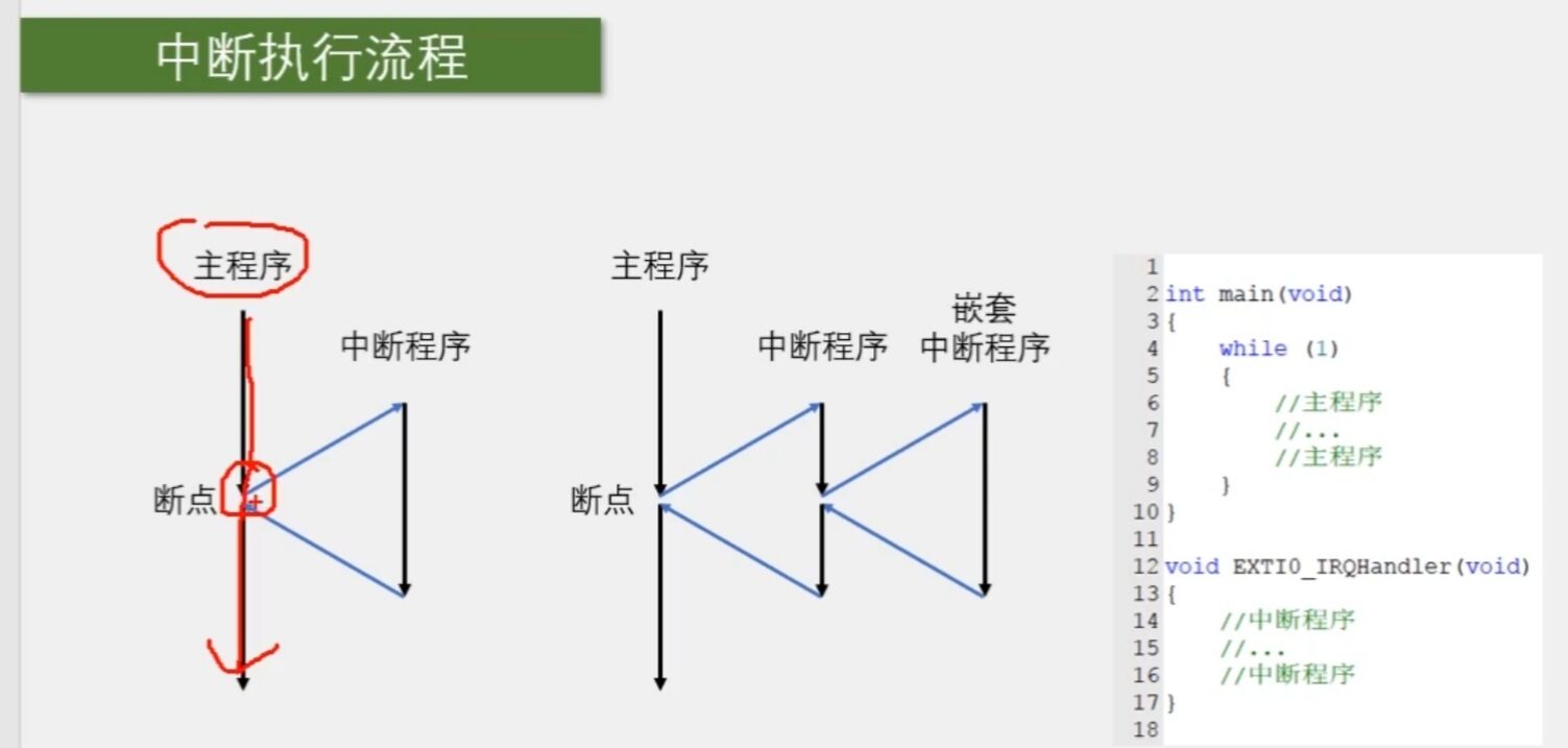
Generally, the interrupt function is in a sub function. We don't need to call this function. When the interrupt comes, the hardware will call this function automatically
II Interrupt of STM32
1. 68 maskable interrupt channels, including EXTI,TIM,ADC,USART,SPI,IIC,RTC and other peripherals
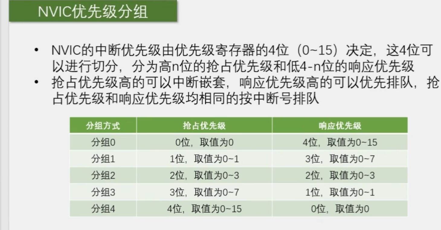
2. Use NVIC to uniformly manage interrupts. Each interrupt has 16 programmable priority levels, which can be grouped
III Introduction to EXTI
1. EXTI external interrupt
2. EXTI can monitor the level signal of the specified GPIO port. When the level of the GPIO port changes, EXTI will immediately send an interrupt application to the NVIC. After the decision of the NVIC, let the CPU execute the interrupt program
3. Trigger mode: rising edge (low to high), falling edge (high to low), bilateral edge (the first two are OK), software start (start by writing code, which has nothing to do with GPIO)
4. GPIO: all GPIO ports are supported, but the same Pin cannot trigger an interrupt
5. Number of channels: 16 pins (plus PVD output, RTC alarm clock, USB wake-up, Ethernet wake-up) - rub the network
6. Trigger response mode: interrupt response, event response
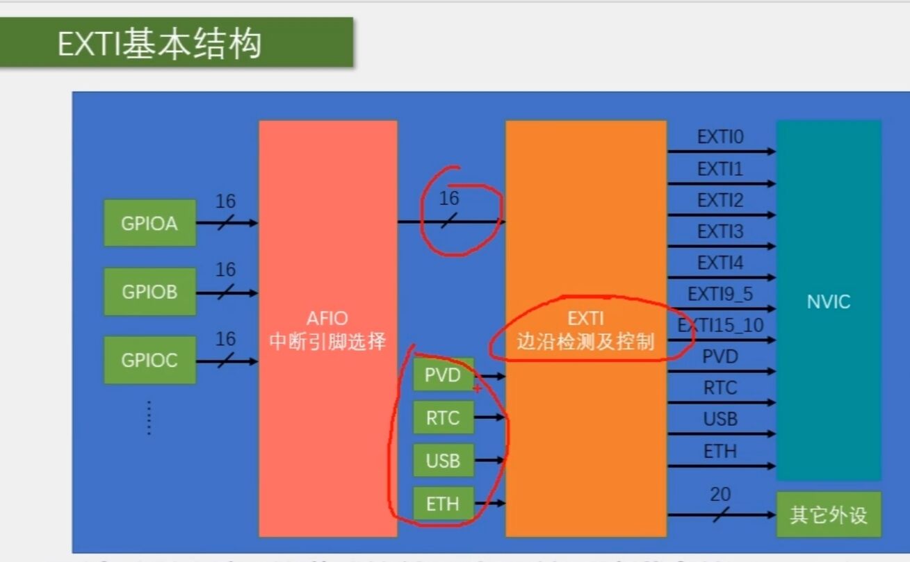
Therefore, PA0, pb0 and PC0 can only have one trigger, and cannot be triggered at the same time
IV AFIO multiplex IO port
In STM32, AFIO port mainly completes two tasks: multiplexing function, pin remapping and interrupt pin selection
V Introduction to rotary encoder
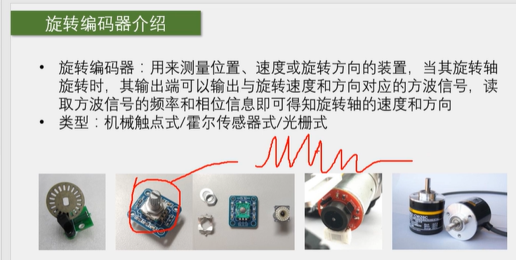
It is an external signal. This signal is burst. STM32 can only be read passively. In case of late reading, many waveforms will be missed, so we have to consider the external interrupt of STM32
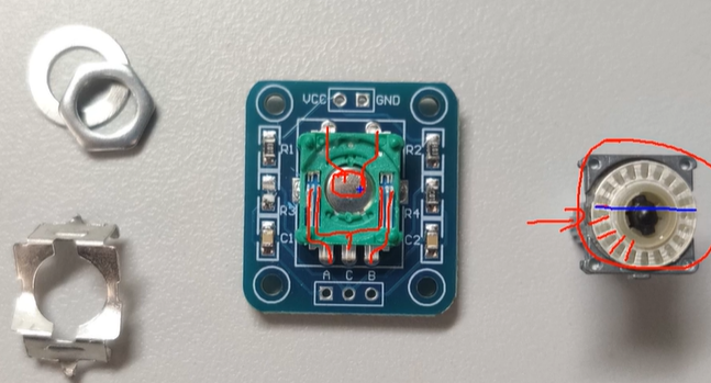
The rotary encoder can be pressed down. At this time, it can be used as an ordinary key
The rotary encoder module has five pins, GND (-), VCC (+), SW, DT and CLK. VCC and GND are used to connect power and ground. According to the abbreviation, SW should be Switch, CLK is Clock and DT is Data
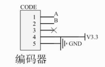
A_CLK B_DT, we didn't connect to C because we didn't use his switch (of course, it can also be used)
Next, go to the code section
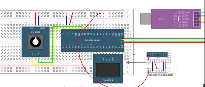
1. Main function
#include "stm32f10x.h"                  // Device header
#include "Delay.h"
#include "OLED.h"
#include "Encoder.h"

//Assigned a value to Num
int16_t Num;

int main(void)
{
	//OLED ENCODER is initialized. It can only be used after initialization
	OLED_Init();
	Encoder_Init();

	OLED_ShowString(1, 1, "Num:");

	while (1)
	{
		Num += Encoder_Get();
		OLED_ShowSignedNum(1, 5, Num, 5);
	}
}
2.Encode.c
#include "stm32f10x.h"     // Device header

//Define a signed variable
int16_t Encoder_Count;

void Encoder_Init(void)
{
	//Initialization code of two interrupts, initialization clock, GPIOB,AFIO
	RCC_APB2PeriphClockCmd(RCC_APB2Periph_GPIOB, ENABLE);
	RCC_APB2PeriphClockCmd(RCC_APB2Periph_AFIO, ENABLE);

	GPIO_InitTypeDef GPIO_InitStructure;
	GPIO_InitStructure.GPIO_Mode = GPIO_Mode_IPU;
	GPIO_InitStructure.GPIO_Pin = GPIO_Pin_0 | GPIO_Pin_1;
	GPIO_InitStructure.GPIO_Speed = GPIO_Speed_50MHz;
	GPIO_Init(GPIOB, &GPIO_InitStructure);

	//Part of AFIO
	GPIO_EXTILineConfig(GPIO_PortSourceGPIOB, GPIO_PinSource0);
	GPIO_EXTILineConfig(GPIO_PortSourceGPIOB, GPIO_PinSource1);

	//The specified interrupt is EXTI_LINE1 and EXTI_LINE0
	EXTI_InitTypeDef EXTI_InitStructure;
	EXTI_InitStructure.EXTI_Line = EXTI_Line0 | EXTI_Line1;
	EXTI_InitStructure.EXTI_LineCmd = ENABLE;
	EXTI_InitStructure.EXTI_Mode = EXTI_Mode_Interrupt;
	EXTI_InitStructure.EXTI_Trigger = EXTI_Trigger_Falling;
	EXTI_Init(&EXTI_InitStructure);

	//Interrupt packet
	NVIC_PriorityGroupConfig(NVIC_PriorityGroup_2);

	//Interrupt priority: set the priority of two channels respectively
	NVIC_InitTypeDef NVIC_InitStructure;
	NVIC_InitStructure.NVIC_IRQChannel = EXTI0_IRQn;
	NVIC_InitStructure.NVIC_IRQChannelCmd = ENABLE;
	NVIC_InitStructure.NVIC_IRQChannelPreemptionPriority = 1;
	NVIC_InitStructure.NVIC_IRQChannelSubPriority = 1;
	NVIC_Init(&NVIC_InitStructure);

	NVIC_InitStructure.NVIC_IRQChannel = EXTI1_IRQn;
	NVIC_InitStructure.NVIC_IRQChannelCmd = ENABLE;
	NVIC_InitStructure.NVIC_IRQChannelPreemptionPriority = 1;
	NVIC_InitStructure.NVIC_IRQChannelSubPriority = 2;
	NVIC_Init(&NVIC_InitStructure);
}

//Return the variable back, return the change value, so return count (here is a trick, indirectly return count (pay the value to temp and let temp go back))
int16_t Encoder_Get(void)
{
	int16_t Temp;
	Temp = Encoder_Count;
	Encoder_Count = 0;
	return Temp;
}

//Next is the interrupt function of the interrupt
void EXTI0_IRQHandler(void)
{
	//Check the interrupt flag bit
	if (EXTI_GetITStatus(EXTI_Line0) == SET)
	{
		//Judge the level of the other pin
		if (GPIO_ReadInputDataBit(GPIOB, GPIO_Pin_1) == 0)
		{
			//If so, reverse
			Encoder_Count --;
		}
		//Clear interrupt flag bit
		EXTI_ClearITPendingBit(EXTI_Line0);
	}
}
//The following is the same, but the line is changed. If it is 9-15, put the two together and use one interrupt
void EXTI1_IRQHandler(void)
{
	if (EXTI_GetITStatus(EXTI_Line1) == SET)
	{
		if (GPIO_ReadInputDataBit(GPIOB, GPIO_Pin_0) == 0)
		{
			//Forward rotation
			Encoder_Count ++;
		}
		EXTI_ClearITPendingBit(EXTI_Line1);
	}
}
3.Encode.h
#ifndef __ENCODER_H
#define __ENCODER_H

void Encoder_Init(void);
int16_t Encoder_Get(void);

#endif