Phase I
First of all, we are working on stm32 learning and project, and encapsulate the corresponding template.
Start with software installation keil 5,keil 5 installation tutorial can be official account of "software housekeeper" and corresponding stm32f1/f4 environment configuration can be directly B war to see video. Next, I'll start with the configuration of the file. If the students who can already configure or want to say that I have directly copied the routines given by the official, they can directly skip to the next stage.
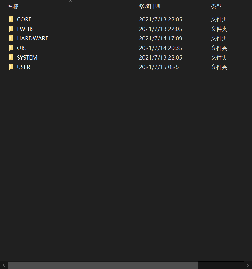
First create a folder in your own disk

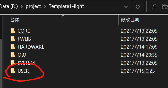
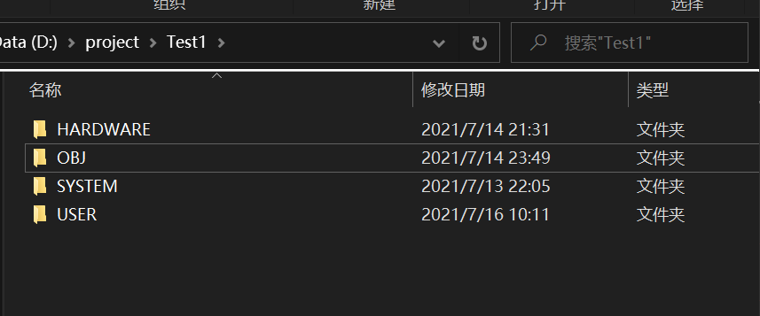
Create the following folder in the folder
Then store the following in the first CORE folder
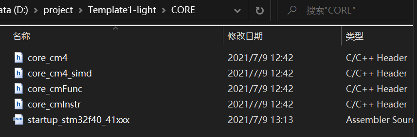
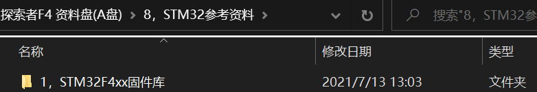
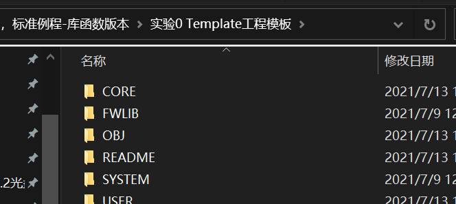
Where can I find this thing? Let's go to the resource package under the official website, or you can find it directly from the resource package given by the merchant
Generally on disk A (of course, it is also possible to directly copy the CORE in the routine, and the effect is the same)

This is the case in FWLIB
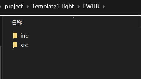
Need to find the file in the firmware library
Just copy it.
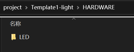
What is stored in HARDWARE is the function of which module you want to implement. For example, in this article, it is used to store the running light
The OBJ folder is found during serial port burning in order to find it better and faster You don't need to create the hex file, because when you start to create the project with keil 5, you will automatically save the objects in USER (if you need to put the. Hex file in OBJ, you need to change the storage path, and you will explain how to change the path in the operation of the next stage)
This is stored in SYSTTEM
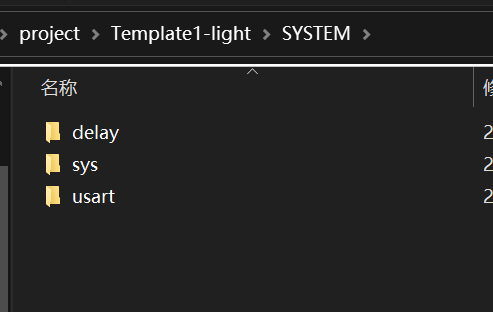
This can be downloaded directly in the routine
copy from the SYSTEM inside
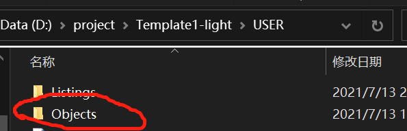
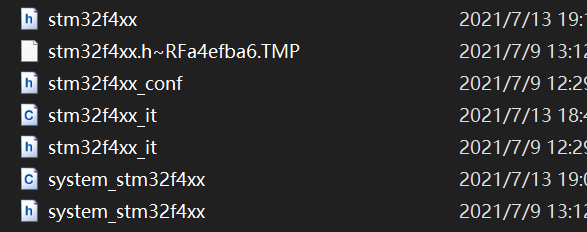
The remaining USER file is where we use it ourselves.
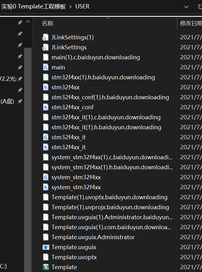
Generally, you need to put these 7 files in the USER folder (you can find them by clicking search in the data disk)
After the above steps are created, you can create the next stage
Phase II
Then go back to keil 5 and start the environment configuration
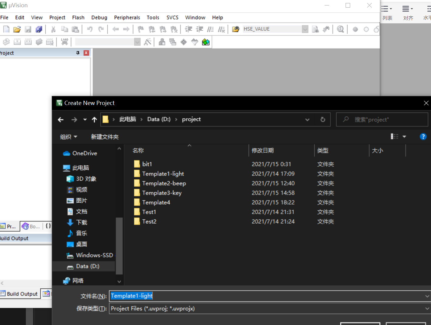
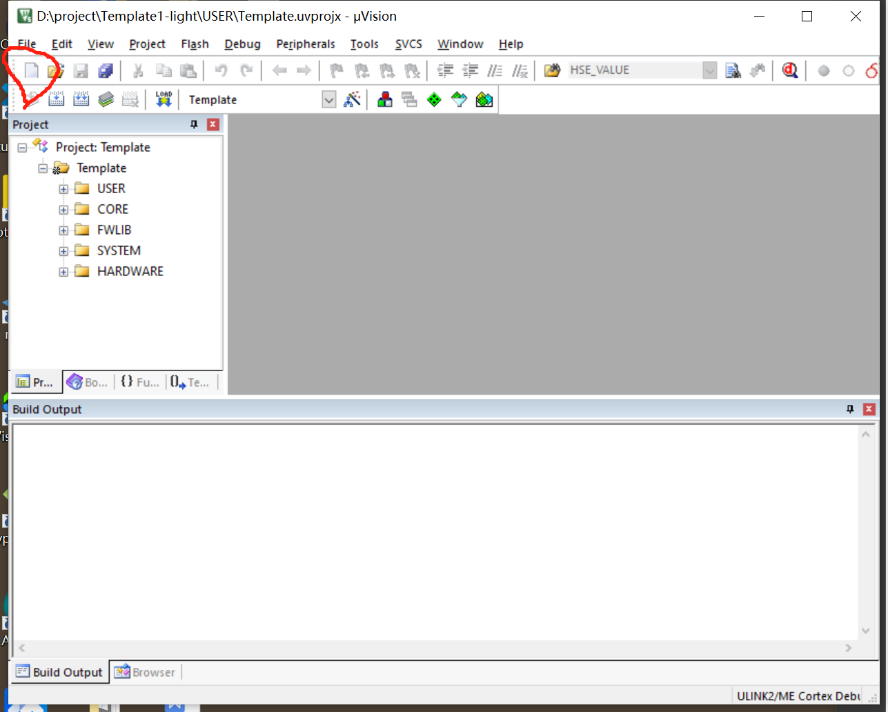
First, click Project and select the first one to create a New uvision project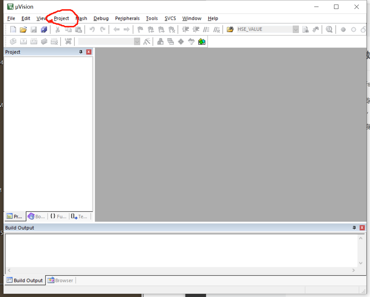
Create a project. Generally, we will create a file with the same name as the initial folder in our last stage
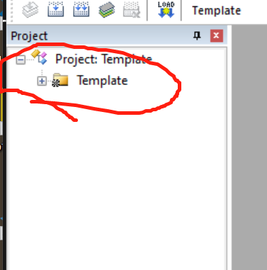
After creation, the following phenomenon will generally appear
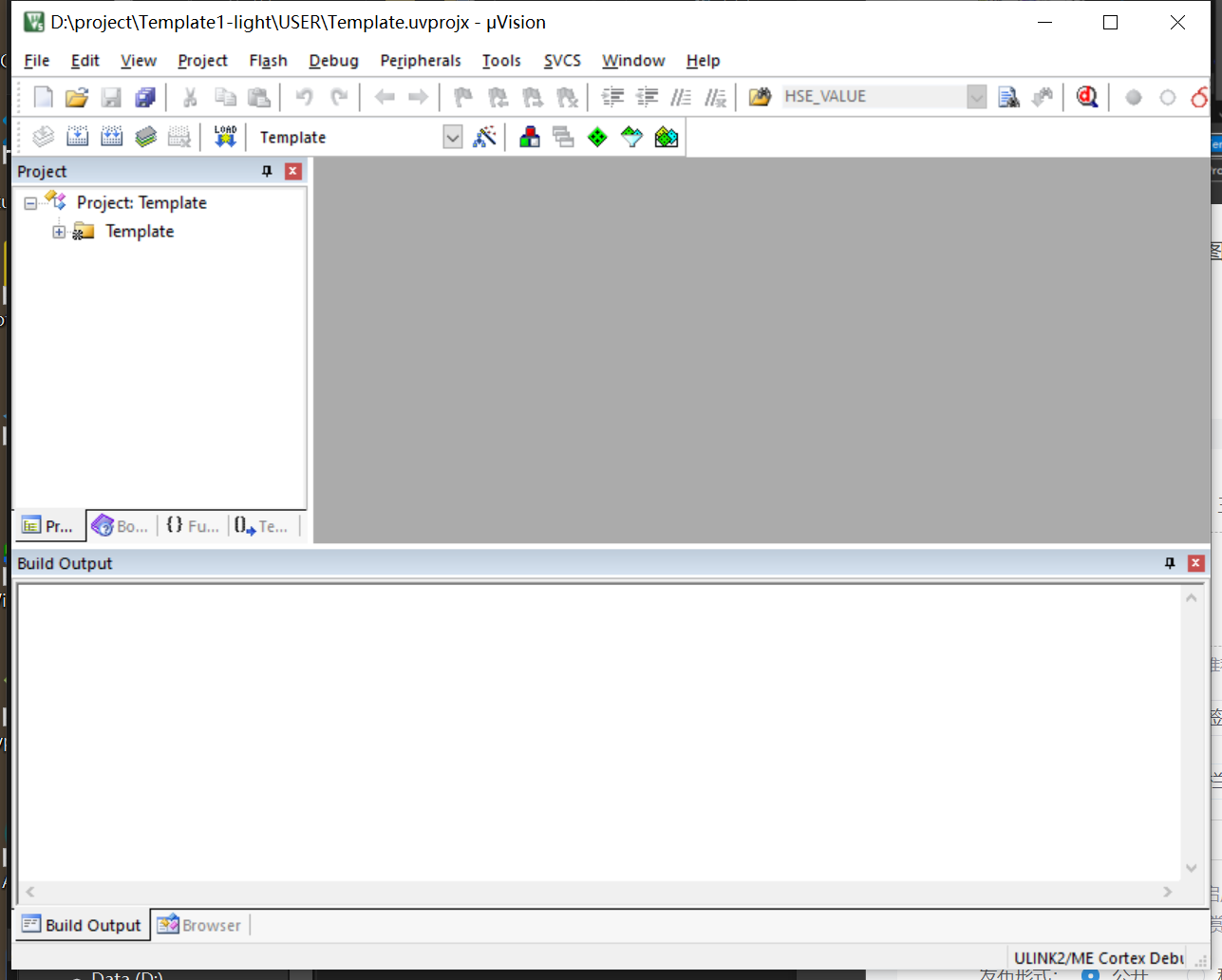
At this time, you need to right-click to open its Template
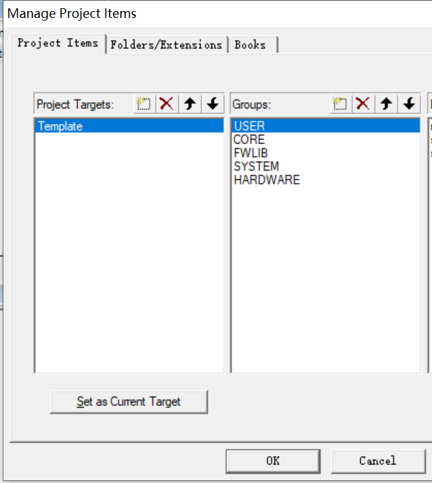
Select the third Manage node to display the following figure
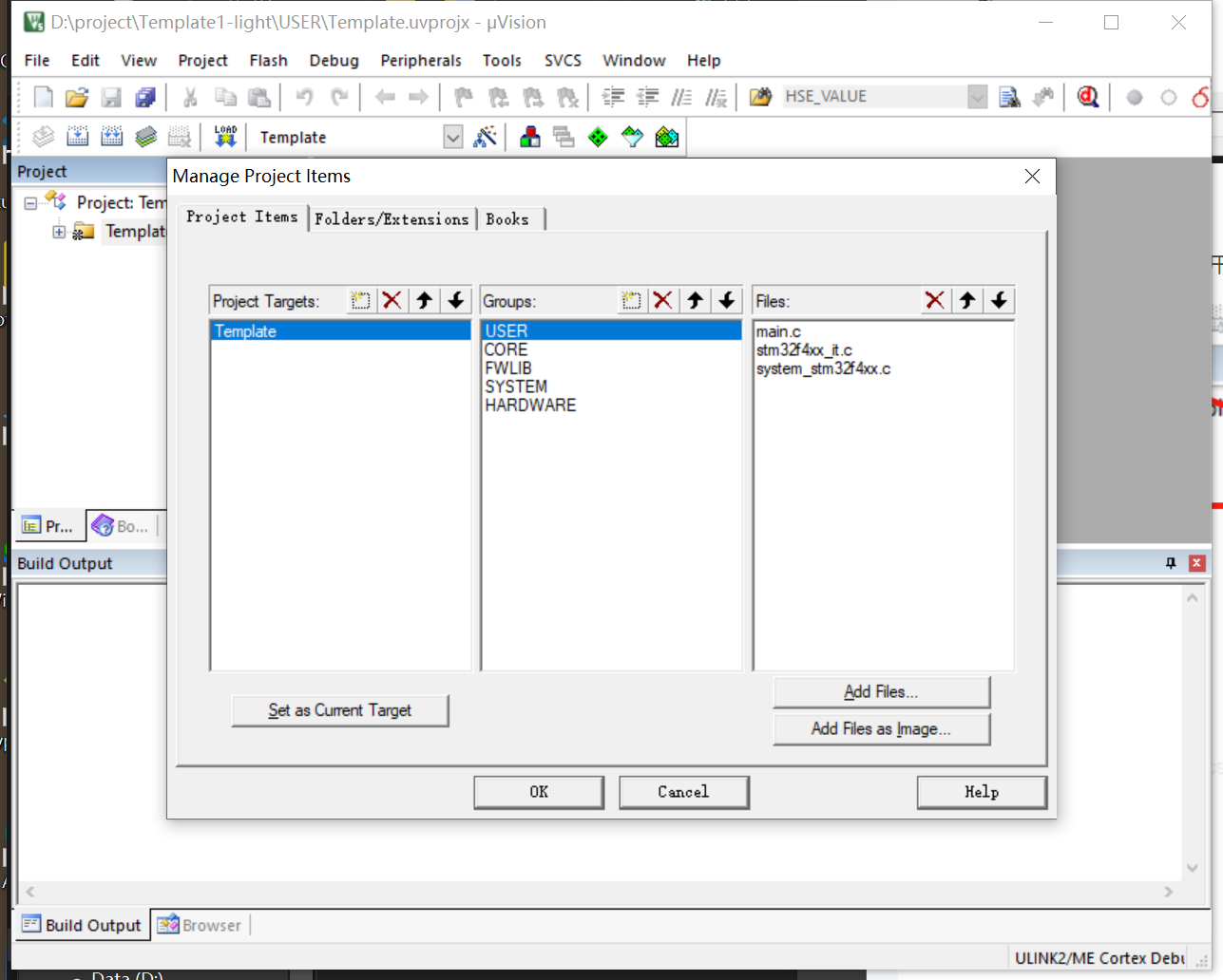
Then you click this in the middle of the middle Groups
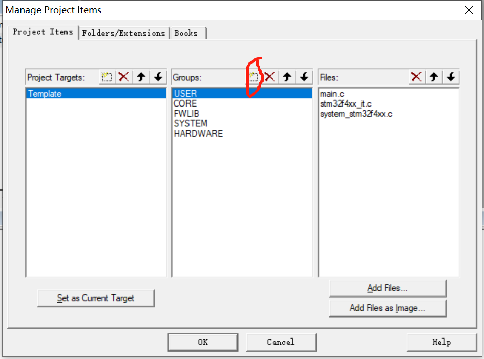
Manually type all the folder names in the last stage (except OBJ, click to type one)
It will have such an effect
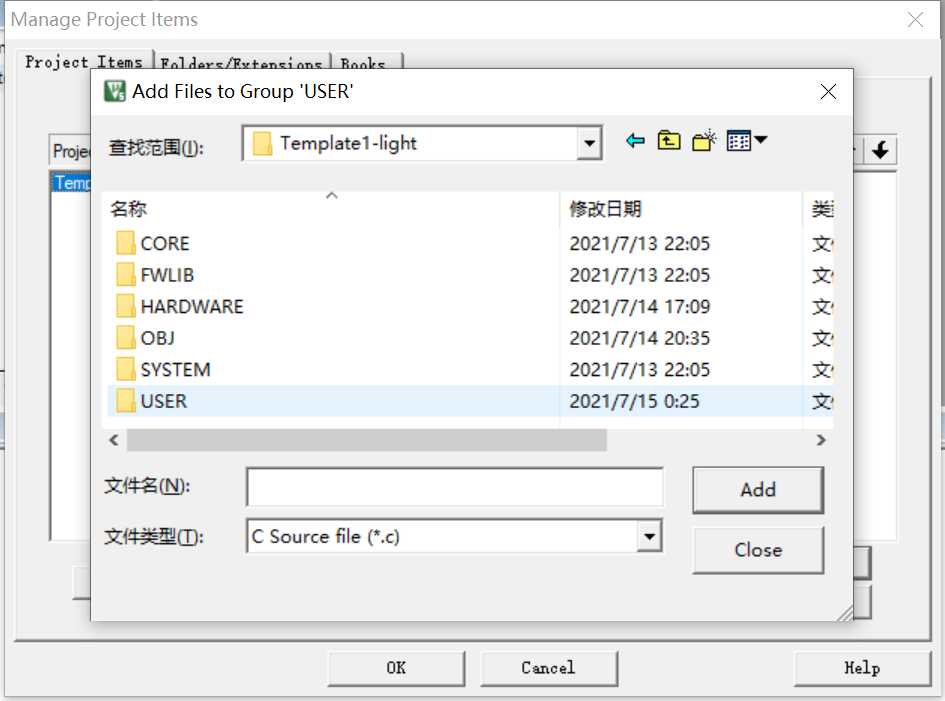
After this setting, you can start adding c files
It is to directly add the things in the previous stage to the file set in keil 5
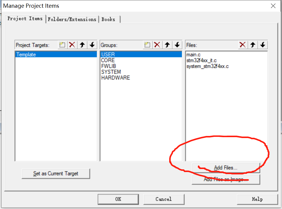
This appears in the back
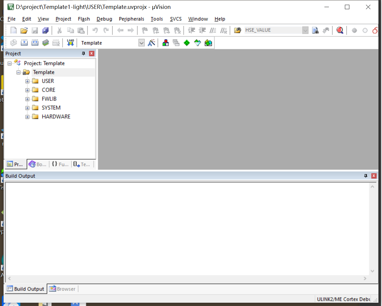
Then click on the magic wand

Point C/C++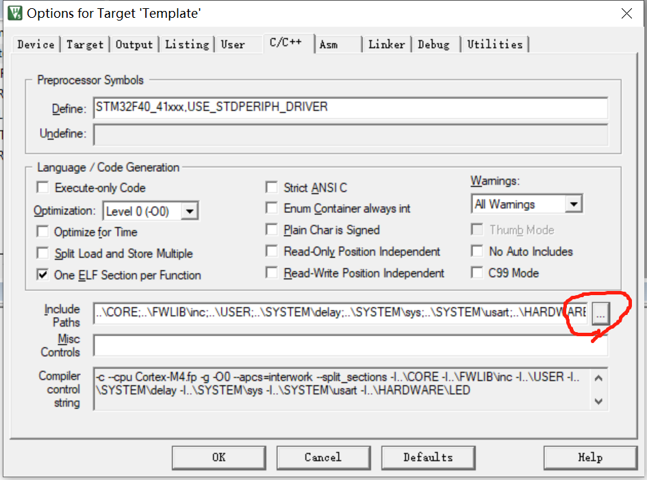
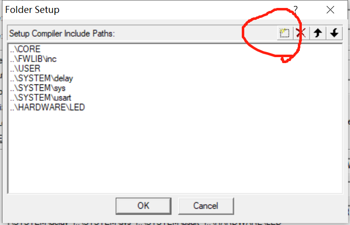
As just now, the last stage will be h file added.
Then you can start typing the code
Click first
Phase III
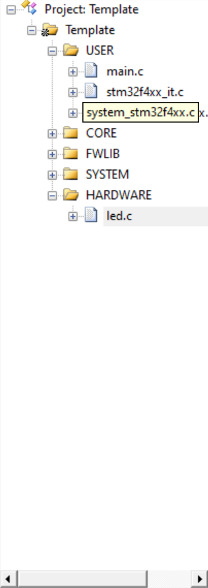
Create main c,led. c,led. h
Creating these three is to separate the use and initialization settings.
Start to get to the point.
The first is to realize the running lamp by using library function
Just set it up, led c,main. c,led. H allocation is placed in USER and HARDWARE in the first stage
Remember that your storage place is in the folder, but it is not displayed on keil 5. In that case, you need to add it as in the previous step
You will create the same main c,led. c,led. H put it in, too
Next, write the code
The first - use library functions - write running lights
Turn the LED H and led Put the functions you want to achieve in C. for example, we realize the function of the running lantern
//led.h
#ifndef  __LED_H

#define  __LED_H

void LED_Init(void);

#endif
It's in here
#ifndef __LED_H
#define __LED_H
#endif
It is to join the system engineering. It does not help us define the led, so it is defined. If it has been defined for us, it is not necessary, but they will not define it again when they read this statement. And in this one, the void LED_Init(void); It is used for function declaration, and the specific function definition and implementation are in led C inside.
led.c
//led.c
#include "led.h" / / refers to the previously defined led H to quote.
#include "stm32f4xx.h" / / is the header file used by stm32 MCU.

 //Here I will explain each step in detail.

//Start with function definition initialization.

 void LED_Init(void)
 {
	 GPIO_InitTypeDef GPIO_InitStructure;
/*Initialize your corresponding GPIO port. How to select this one will be reflected in the screenshot below. This statement is defined*/
	 //F9
	 RCC_AHB1PeriphClockCmd(RCC_AHB1Periph_GPIOF,ENABLE);/*Here is the definition of the clock. The clock is the pulse of the single chip microcomputer. It will promote the amount instruction of the single chip microcomputer*/
//The following is the definition of the pin or GPIO port used by the single chip microcomputer
//This involves registers. MCU generally has 10 registers, but we generally use five registers in GPIO port
//Corresponding to which specific pin, mode, frequency, etc
	 GPIO_InitStructure.GPIO_Pin=GPIO_Pin_9;
	 GPIO_InitStructure.GPIO_Mode=GPIO_Mode_OUT;
	 GPIO_InitStructure.GPIO_OType=GPIO_OType_PP;
	 GPIO_InitStructure.GPIO_PuPd=GPIO_PuPd_UP;
	 GPIO_InitStructure.GPIO_Speed=GPIO_Speed_50MHz;

//Initialize and store it
	 GPIO_Init(GPIOF,&GPIO_InitStructure);
	 GPIO_SetBits(GPIOF,GPIO_Pin_9);//The default initialization is high power frequency
//The following is the same as above

	 //F10
	 GPIO_InitStructure.GPIO_Pin=GPIO_Pin_10;
	 GPIO_InitStructure.GPIO_Mode=GPIO_Mode_OUT;
	 GPIO_InitStructure.GPIO_OType=GPIO_OType_PP;
	 GPIO_InitStructure.GPIO_PuPd=GPIO_PuPd_UP;
	 GPIO_InitStructure.GPIO_Speed=GPIO_Speed_50MHz;


	 GPIO_Init(GPIOF,&GPIO_InitStructure);
	  GPIO_SetBits(GPIOF,GPIO_Pin_10);


 }
For main function
#include "stm32f4xx.h" / / the explanation here refers to the above code
#include "led.h"
#include "delay.h"

int main(void)
{
	delay_init(168);/*For the initialization of the delay function, you need to call the delay function not only to include the header file, but also to initialize its call*/
	LED_Init();//In LED There is an initialization definition in H, where led initialization is called

	while(1)//You need to keep cycling, or the MCU will stop cycling again
	{
			 GPIO_SetBits(GPIOF,GPIO_Pin_9);//Turn up the level of the corresponding pin and the light goes out
			 GPIO_SetBits(GPIOF,GPIO_Pin_10);
		delay_ms(500);
		GPIO_ResetBits(GPIOF,GPIO_Pin_9);//Turn down the level of the corresponding pin and the light will be on
			 GPIO_ResetBits(GPIOF,GPIO_Pin_10);
		delay_ms(500);
	}

}
The second - in the library function with bit operation - write the running lantern
led.c and led H is written in the same way as above
It's in main C different
#include "stm32f4xx.h"
#include "led.h"
#include "delay.h"

int main(void)
{
	delay_init(168);
	LED_Init();

	while(1)
	{
			// GPIO_SetBits(GPIOF,GPIO_Pin_9);
			 //GPIO_SetBits(GPIOF,GPIO_Pin_10);
		PFout(9)=1;//It directly uses PFout() function to realize bit operation, so that it can directly assign value and adjust high and low levels
		PFout(10)=1;
		delay_ms(500);
		//GPIO_ResetBits(GPIOF,GPIO_Pin_9);
			// GPIO_ResetBits(GPIOF,GPIO_Pin_10);
		PFout(9)=0;
		PFout(10)=0;
		delay_ms(500);
	}

}
The third - use register - write Marquee
When configuring files, it does not need as many library functions as it does, and only a few are enough
Moreover, it directly assigns functions to other low-level code blocks (the library function itself uses registers based on function definitions)
//main.c
#include "stm32f4xx.h"
#include "led.h"
#include "delay.h"

int main(void)
{
	delay_init(168);
	 LED_Init();
	while(1)
	{
		GPIOF->ODR&=~(1<<9);
		GPIOF->ODR&=~(1<<10);
		delay_ms(50);
		GPIOF->ODR|=1<<9;
		GPIOF->ODR|=1<<10;
		delay_ms(50);

	}

}
Article reprinted to