Overview of the principle of independent watchdog
Why watchdog:
In the microcomputer system consisting of single-chip computer, because the work of single-chip computer is often interfered by external electromagnetic fields, causing the program to run away and fall into an endless cycle, the normal operation of the program is interrupted, the system controlled by single-chip computer can not continue to work, causing the whole system to fall into a stagnant state, with unexpected consequences. Therefore, for the consideration of real-time monitoring of the operation status of single-chip computer, a module or chip, commonly known as watchdog, has been created to monitor the operation status of single-chip computer programs.
What does the watchdog solve?
The system cannot be reset at startup
In case the system runs (program executes abnormally), reset the system and execute the program again
Overview of independent watchdog:
STM32 has two built-in watchdogs: the stand-alone watchdog and the window watchdog.
The two watchdog provides greater security, time accuracy and flexibility in use.
Two watchdog devices (stand-alone watchdog/window watchdog) can be used to detect and resolve failures caused by software errors. When the counter reaches the given timeout value, it triggers an interrupt (only for the window watchdog) or a system reset.
The stand-alone watchdog (IWDG) is driven by a dedicated low-speed clock (LSI), which is effective even if the main clock fails.
Independent watchdog is suitable for situations where a watchdog is required to work completely independently outside of the main program and has a low time accuracy requirement.
The window watchdog is driven by a clock obtained after frequency division from the APB1 clock. Detect abnormal late or premature operation of the application through a configurable time window. The window watchdog is best suited for programs that require the watchdog to function within the precise timing window.
The M7 independent watchdog can also be configured for use as a window watchdog.
Because the M7 itself has a window watchdog, we rarely use this feature in general.
Description of working principle of independent watchdog
Write 0xCCCC in key register (IWDG_KR) to start enabling stand-alone watchdog. The counter starts to decrease from its reset value of 0xFFF, and a reset signal (IWDG_RESET) is generated when the counter value is counted to the end value of 0x000.
Whenever the key value register IWDG_ Write 0xAAAA (usually dog feed) in KR to automatically reload register IWDG_ The RLR value is reloaded to the counter to avoid watchdog reset.
If the program is abnormal, the dog will not be fed properly and the system will be reset.
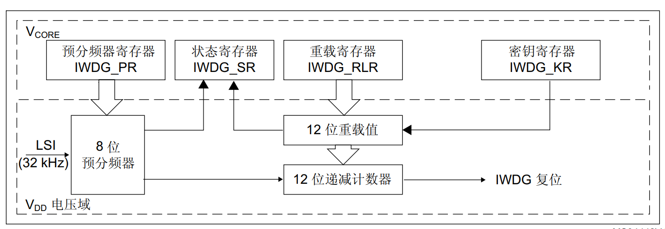
Block Diagram of Independent Watchdog
The clock comes from LSI and passes through frequency division to produce a clock that enters a 12-bit decrement counter. Write 0xcccc in the key register first, then start counting from the initial value. If 0xaaaa is written in the key register, the value in the RLR register is reloaded to the counter. When the program does not feed the dog properly, it drops to zero and a reset signal is generated.
Independent Watchdog Timeout
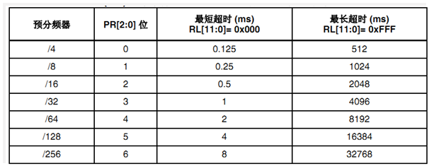
Overflow time calculation:
Tout=((4×2^prer) ×rlr) /32 (M4)
32 /(4) × 2^ prer) is the frequency after crossover. Where prer is the set PR[2:0] bit and then the reverse is the cycle, then the overflow time is ((4) × 2^ prer) × rlr) /32, where rlr is the value of the reload register.
Clock frequency LSI=32K, a watchdog clock cycle is the minimum time-out.
Maximum timeout = (maximum IWDG_RLR register) X watchdog clock cycle.
For example, if you want to set the watchdog overflow time to 1 s, first because the clock frequency LSI=32k, and then if the pre-crossover frequency is 64, then LSI/64=0.5khz, which means you can set the rlr value to 500, then the overflow time is 1s. Note that the maximum reload register rlr value is 2^12-1 and cannot be greater than it.
Independent Watchdog Register
IWDG_KR: Key register, 0~15 bits valid
IWDG_PR: Pre-crossover register, 0~2 bits valid. Write protection, write protection must be removed before operation
IWDG_RLR: Reload registers, 0-11 bits valid. Has write protection function, write protection should be removed before operation.
IWDG_SR: Status register, 0~1 bits valid
Key Register: IWDG_KR
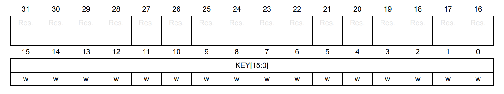
KEY[15:0]: Key value (write only, read 0x0000)
The key value 0xAAAA must be written to these bits by the software at regular intervals, or the watchdog will reset when the counter counts to zero.
Writing the key value 0x5555 makes it possible to write to IWDG_PR, IWDG_RLR and IWDG_ Access to WINR Registers
Writing a key value of 0xCCCC starts the watchdog (except when the hardware watchdog option is selected)
Pre-crossover register: IWDG_PR
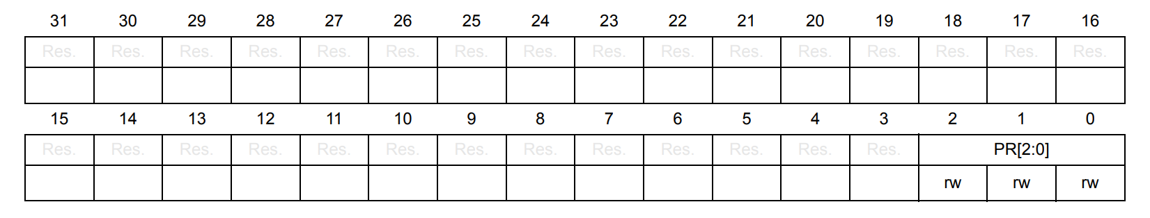
Bit 2:0 PR[2:0]: Prescaler divider
These bits are protected by write access. Select the pre-dividing factor of the counter clock by setting these bits by the software. To change the dividing factor of the prescaler, IWDG_ The PVU bit for SR must be 0.
000:4 crossover
001:8 crossover
010:16 crossover
011:32 crossover
100:64 crossover
101:128 crossover
110:256 crossover
111:256 crossover
Reload Register: IWDG_RLR
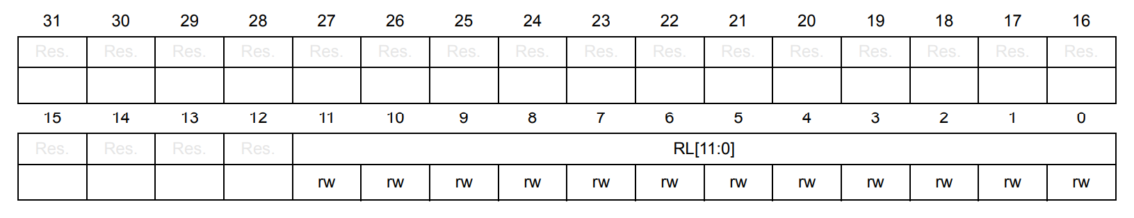
Bit 11:0 RL[11:0]: Watchdog counter reload value
These bits are protected by write access. This value is set by the software, once for IWDG_ When the KR register writes a value of 0xAAAA, this value is reloaded into the watchdog counter. The watchdog counter then decreases from the loaded value. The timeout period is determined by this value together with the clock pre-divider.
To change the overload value, IWDG_ RVU bit in SR must be 0
Status Register: IWDG_SR
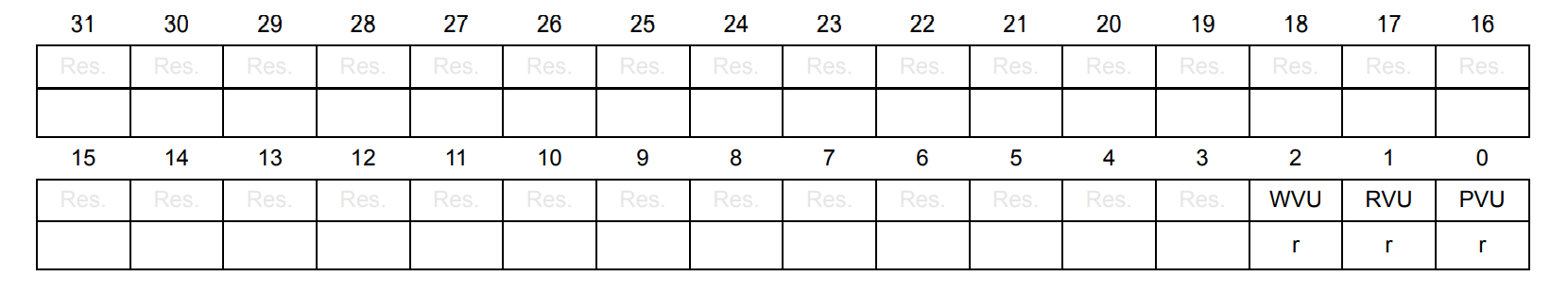
Bit 31:3 is reserved and reset values must be maintained.
Bit 2 WVU: Watchdog counter window value update can use hardware to position 1 to indicate that the window value is being updated. When the overload value update operation is completed in the VDD voltage domain (up to 5 RC 40 kHz cycles are required), the bit will be reset by hardware. The window value can only be updated if the WVU bit is 0. This bit is only generated when the generic Window = 1.
Bit 1 RVU: Watchdog counter reload value update can use hardware to indicate that the overload value is being updated. When the overload value update operation is completed in the VDD voltage domain (up to 5 RC 40 kHz cycles are required), the bit will be reset by hardware. The overload value can only be updated if the RVU bit is 0.
Bit 0 PVU: Watchdog prescaler value update can be hardware-enabled to indicate that the prescaler value is being updated. When the pre-divider value update operation is completed in the VDD voltage domain (up to 5 RC 40 kHz cycles are required), the bit will be reset by hardware. The pre-divider value can only be updated if the PVU bit is 0.
IWDG Independent Watchdog Operates HAL Library Functions
HAL_StatusTypeDef HAL_IWDG_Init(IWDG_HandleTypeDef *hiwdg); Initialization Function for Independent Watchdog
Find the definition of the parameter: you can find handles similar to other peripherals. The first member variable is the base address of the peripheral.
typedef struct
{
  IWDG_TypeDef                 *Instance;  /*!< Register base address    */

  IWDG_InitTypeDef             Init;       /*!< IWDG required parameters */

  HAL_LockTypeDef              Lock;       /*!< IWDG Locking object      */

  __IO HAL_IWDG_StateTypeDef   State;      /*!< IWDG communication state */
}IWDG_HandleTypeDef;
Then find the second variable, IWDG_ Definition of InitTypeDef: Prescaler is configured with a prescaler factor and Reload is configured with a reload value.
typedef struct
{
  uint32_t Prescaler;  /*!< Select the prescaler of the IWDG.
                            This parameter can be a value of @ref IWDG_Prescaler */

  uint32_t Reload;     /*!< Specifies the IWDG down-counter reload value.
                            This parameter must be a number between Min_Data = 0 and Max_Data = 0x0FFF */
}IWDG_InitTypeDef;
void HAL_IWDG_MspInit(IWDG_HandleTypeDef *hiwdg); Initialize callback function
HAL_StatusTypeDef HAL_IWDG_Start(IWDG_HandleTypeDef *hiwdg); Start independent watchdog
HAL_StatusTypeDef HAL_IWDG_Refresh(IWDG_HandleTypeDef *hiwdg); feed a dog
Independent Watchdog Procedures
1. Initialize watchdog: Pre-crossover factor, reload value.
HAL_IWDG_Init();
This function removes write protection before manipulating PR and RLR registers.
2. Start the watchdog
HAL_IWDG_Start();
3. Feeding the dog:
HAL_IWDG_Refresh();
Independent Watchdog Experiment
Initialize Watchdog
How to write, first look at what functions are inside the file, then find the parameters, and then adjust the function.
Call HAL_based on step 1 IWDG_ Init function:
Find HAL_first IWDG_ Init independent watchdog initialization function:
HAL_StatusTypeDef HAL_IWDG_Init(IWDG_HandleTypeDef *hiwdg)
{
  /* Check the IWDG handle allocation */
  if(hiwdg == NULL)
  {
    return HAL_ERROR;
  }

  /* Check the parameters */
  assert_param(IS_IWDG_ALL_INSTANCE(hiwdg->Instance));
  assert_param(IS_IWDG_PRESCALER(hiwdg->Init.Prescaler));
  assert_param(IS_IWDG_RELOAD(hiwdg->Init.Reload));

  if(hiwdg->State == HAL_IWDG_STATE_RESET)
  {
    /* Allocate lock resource and initialize it */
    hiwdg->Lock = HAL_UNLOCKED;
    /* Init the low level hardware */
    HAL_IWDG_MspInit(hiwdg);
  }

  /* Change IWDG peripheral state */
  hiwdg->State = HAL_IWDG_STATE_BUSY;

  /* Enable write access to IWDG_PR and IWDG_RLR registers */
  IWDG_ENABLE_WRITE_ACCESS(hiwdg);

  /* Write to IWDG registers the IWDG_Prescaler & IWDG_Reload values to work with */
  MODIFY_REG(hiwdg->Instance->PR, IWDG_PR_PR, hiwdg->Init.Prescaler);
  MODIFY_REG(hiwdg->Instance->RLR, IWDG_RLR_RL, hiwdg->Init.Reload);

  /* Change IWDG peripheral state */
  hiwdg->State = HAL_IWDG_STATE_READY;

  /* Return function status */
  return HAL_OK;
}
Now you know that the parameter is a structure and write it in the main:
IWDG_HandleTypeDef iwdg_handler;
HAL_IWDG_Init(&iwdg_handler);
Then start with iwdg_handler's parameters are set so you can see HAL_first IWDG_ In the Init function, there is a pair of IWDG_ Functions that operate on HandleTypeDef types. So we can find the definition of this function.
  assert_param(IS_IWDG_ALL_INSTANCE(hiwdg->Instance));
  assert_param(IS_IWDG_PRESCALER(hiwdg->Init.Prescaler));
  assert_param(IS_IWDG_RELOAD(hiwdg->Init.Reload));
IS_IWDG_ALL_INSTANCE is defined as follows:
#define IS_IWDG_ALL_INSTANCE(INSTANCE) ((INSTANCE) == IWDG)
So you know that INSTANCE should be set to IWDG. This is called validity judgment.
So main writes: iwdg_handler.Instance = IWDG;
So one member variable is set, and so is another variable.
You can find Prescaler-related definitions and write them in main
iwdg_handler.Init.Prescaler = IWDG_PRESCALER_64;
#define IS_IWDG_PRESCALER(__PRESCALER__) (((__PRESCALER__) == IWDG_PRESCALER_4)  || \
                                          ((__PRESCALER__) == IWDG_PRESCALER_8)  || \
                                          ((__PRESCALER__) == IWDG_PRESCALER_16) || \
                                          ((__PRESCALER__) == IWDG_PRESCALER_32) || \
                                          ((__PRESCALER__) == IWDG_PRESCALER_64) || \
                                          ((__PRESCALER__) == IWDG_PRESCALER_128)|| \
                                          ((__PRESCALER__) == IWDG_PRESCALER_256))
If you want to set the watchdog overflow time to 1 s, first because the clock frequency LSI=32k, and if the pre-crossover frequency is 64, then LSI/64=0.5khz, which means you can set the value of rlr to 500, then the overflow time is 1s.
iwdg_handler.Init.Reload = 500;
Start Watchdog
Then start calling HAL_IWDG_Start function.
HAL_IWDG_Start(&iwdg_handler);
feed a dog
HAL_ IWDG_ Refresh (&iwdg_handler);// feed a dog
main code:
The key has not been pressed (feed the dog) since the system was reset. Once the overflow time (1s) is reached, a reset will occur. If the system is reset, the led lights will go out and the led lights will go on when the system is initialized, so if the key is not pressed all the time, the led lights of the system will flash.
If you press a key, that is, the feed cycle is less than the overflow time, the program will not reset, and the led light will always be on because the initial led light is on before the while executes and the program will always execute in the while cycle if the dog has been fed.
#include "sys.h"
#include "delay.h"
#include "usart.h"
#include "led.h"
#include "key.h"
#include "exti.h"

IWDG_HandleTypeDef iwdg_handler;

int main(void)
{

  HAL_Init();                     //Initialize HAL Library
  Stm32_Clock_Init(360,25,2,8);   //Set clock, 180Mhz
  delay_init(180);                //Initialization Delay Function
  uart_init(115200);              //Initialize USART
  LED_Init();                     //Initialize LED
	EXTI_Init();
	delay_ms(100);
	iwdg_handler.Instance = IWDG;

	iwdg_handler.Init.Prescaler = IWDG_PRESCALER_64;

	iwdg_handler.Init.Reload = 500;

	HAL_IWDG_Init(&iwdg_handler);
	HAL_IWDG_Start(&iwdg_handler);

	LED0=0;

	while(1)
	{
		if(KEY_Scan(0)==WK_UP)//Detect WK_ Whether the UP key is pressed
		{
			HAL_IWDG_Refresh(&iwdg_handler);//feed a dog
			delay_ms(10);
		}
	}
}