1, CubeMX interrupt lighting
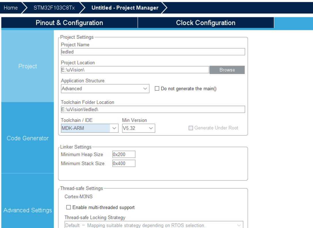
1. CubeMX project settings
Create a new project and select STM32F103C8 chip.
Pin settings:
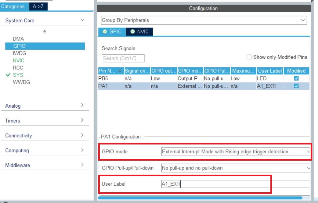
Set the indicator LED pin PB5 and set the pin mode to output mode GPIO_Output
Set key pin PA1, set pin to external interrupt function, and PA1 is connected to GPIO with external interrupt line exit1_ EXIT1
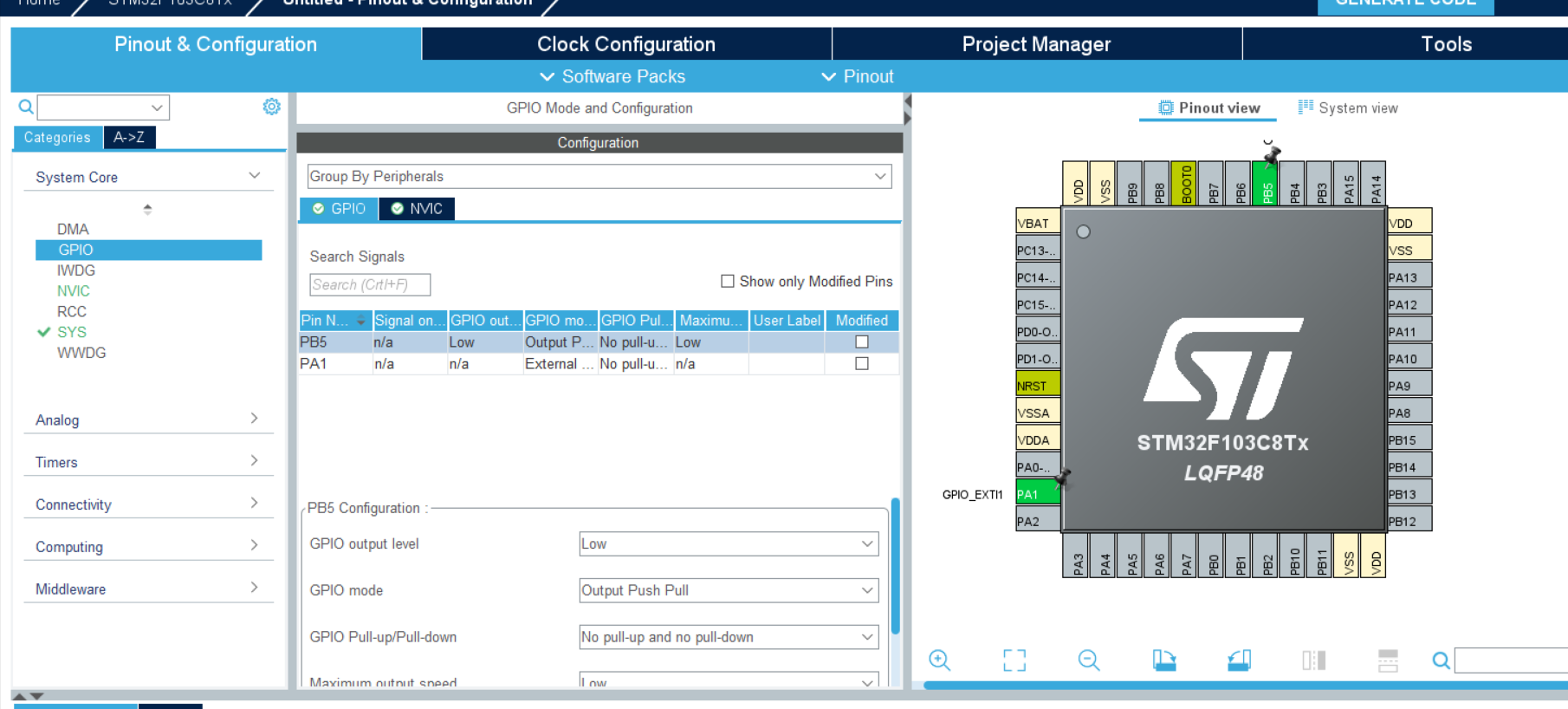
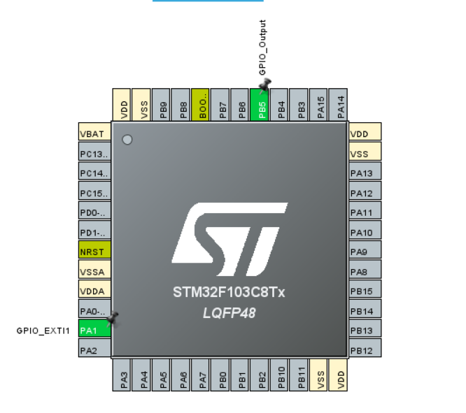
For the PB5 pin corresponding to the LED, the default setting is OK, and the name is set to LED
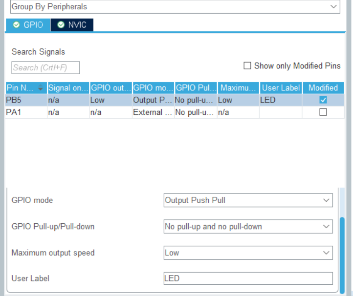
For the pin PA1 corresponding to the switch, set its trigger mode as rising edge trigger
Set the name to A1 at the User Label_ EXTI
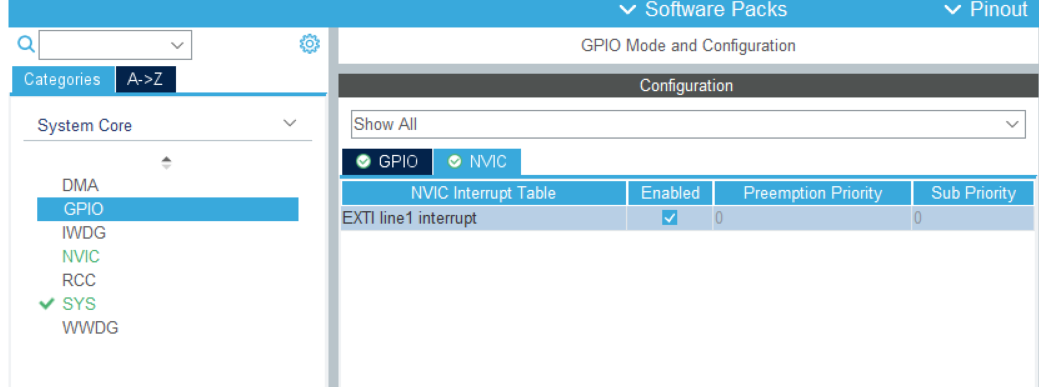
Enable the corresponding external interrupt line and click Enabled
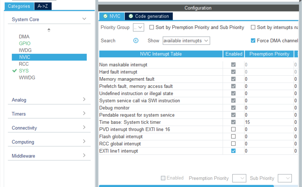
Configure interrupt priority
Clock setting
Set to 36M
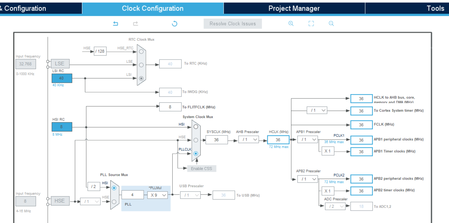
Then generate the project file.
2. Code writing
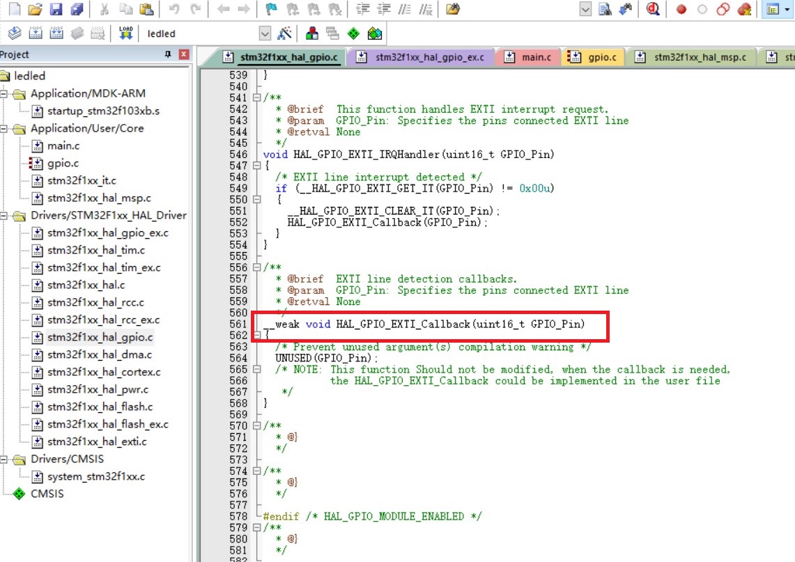
Open the following file in Keil file:
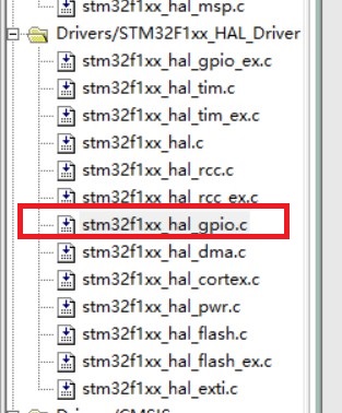
You can find a break in front. Front__ weak indicates that this function is a virtual function and needs to be rewritten by the user.
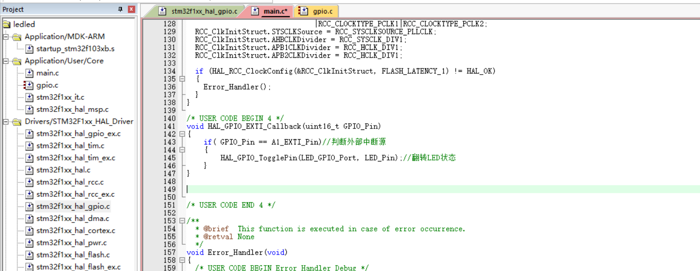
Then write it again somewhere in the main.c file.
The position is below the main function.
void HAL_GPIO_EXTI_Callback(uint16_t GPIO_Pin)
{
	if( GPIO_Pin == A1_EXTI_Pin)//Determine external interrupt source
	{
		HAL_GPIO_TogglePin(LED_GPIO_Port, LED_Pin);//Flip LED status
	}
}
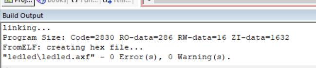
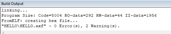
No errors and warnings were found after compilation.
Burn the code into the C8T6 core board
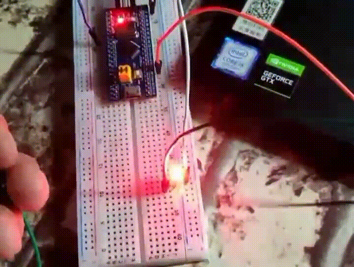
3. Circuit connection
LED long pin - 3V3
LED short pin - PB5
PA1 - 3V3 - light on
PA1 - GND - light off
design sketch:
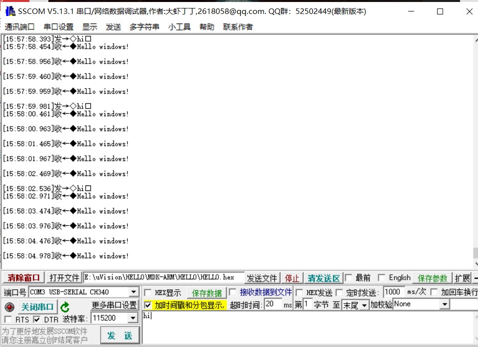
2, Interrupt mode serial communication
Set the serial port to automatically send Hello windows!, If other data is received, return other data, and then continue to send Hello windows.
1. Engineering setting
Create a new project and select the corresponding chip.
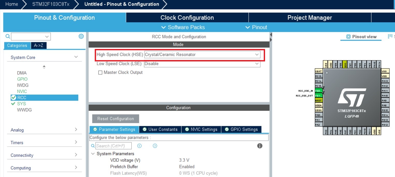
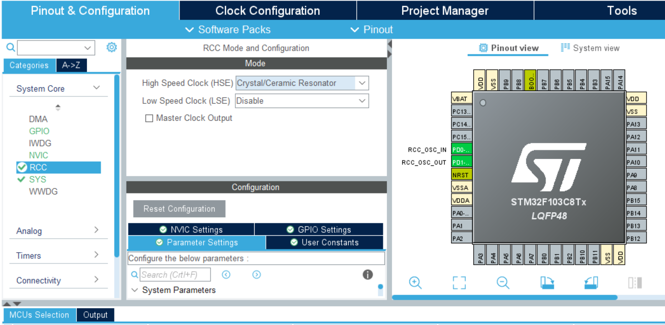
Setting RCC
Set the high-speed external clock HSE and select the external clock source
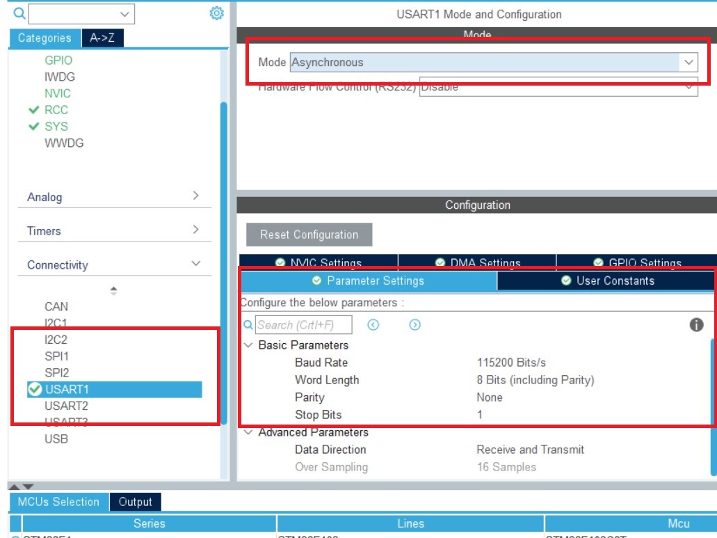
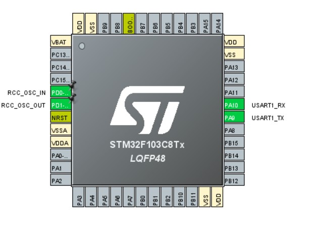
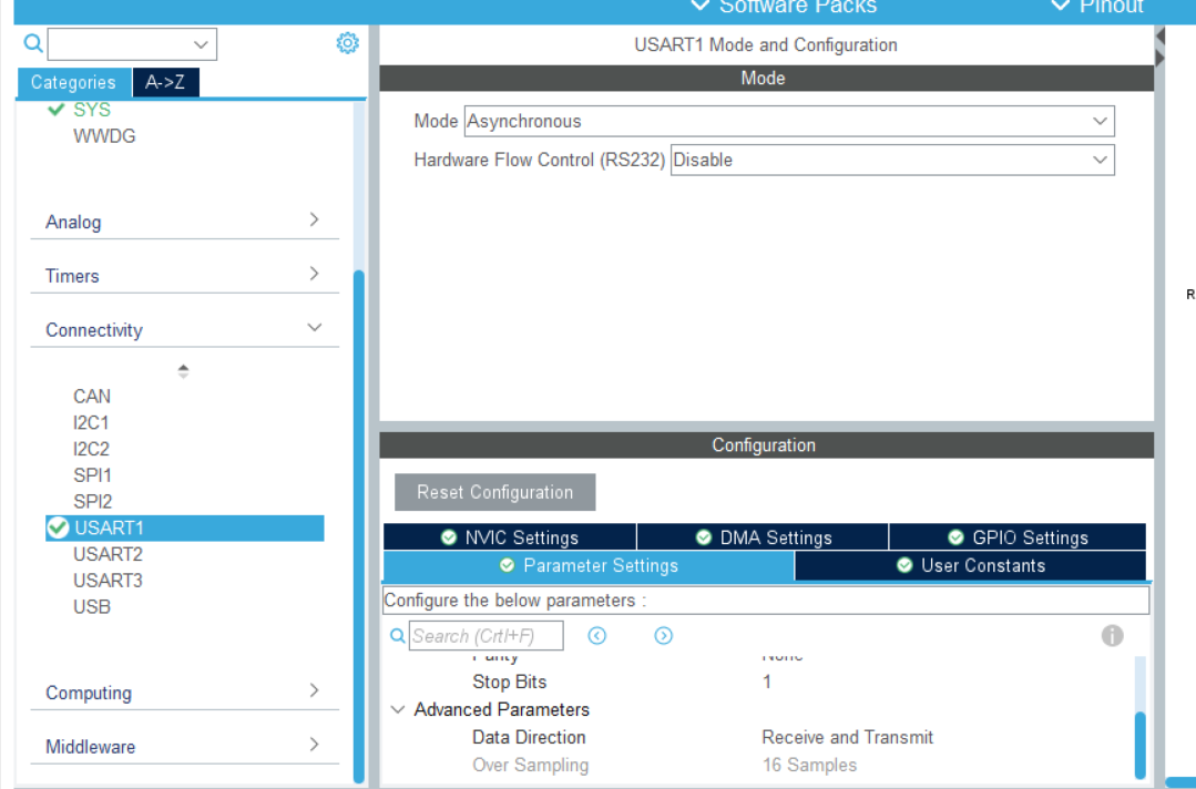
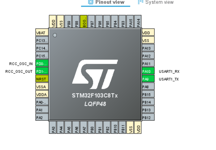
Set serial port
1) Click USART1 and set MODE as asynchronous communication. Basic parameter: baud rate is 115200 Bits/s. The transmission data length is 8 bits. Parity check none, stop bit 1, both receive and transmit are enabled
2) GPIO pin setting USART1_RX/USART_TX (it is generally set automatically here)
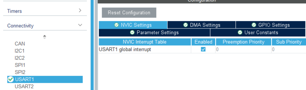
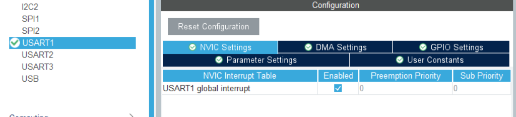
3) The NVIC Settings column enables to receive interrupts
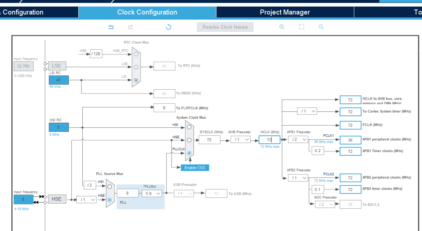
Clock setting
Set to 72
Then export the Keil file and open it.
2. Code writing
printf function settings
Add header file #include "stdio.h" in main.c and usart.c
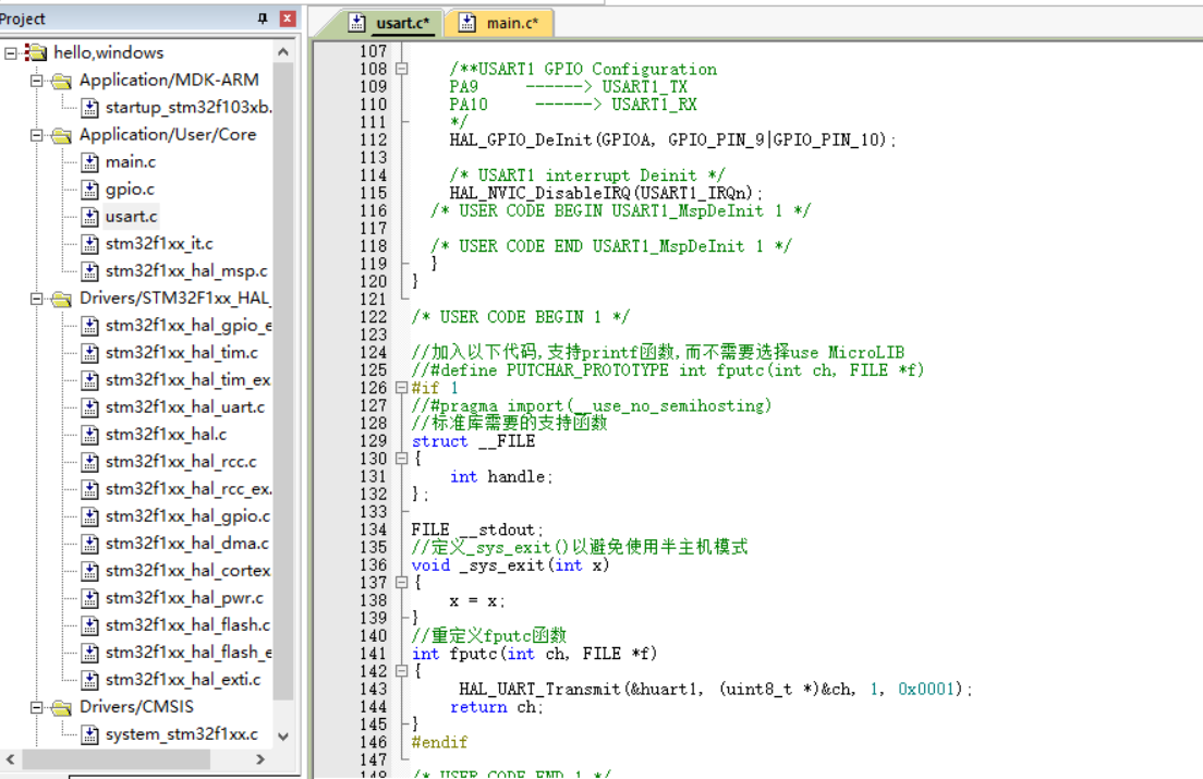
Then, add the following code to the usart.c file for redefinition
/* USER CODE BEGIN 1 */

//Add the following code to support the printf function without selecting use MicroLIB
//#define PUTCHAR_PROTOTYPE int fputc(int ch, FILE *f)
#if 1
//#pragma import(__use_no_semihosting)
//Support functions required by the standard library
struct __FILE
{
	int handle;
};

FILE __stdout;
//Definition_ sys_exit() to avoid using half host mode
void _sys_exit(int x)
{
	x = x;
}
//Redefine fputc function
int fputc(int ch, FILE *f)
{
	 HAL_UART_Transmit(&huart1, (uint8_t *)&ch, 1, 0x0001);
	return ch;
}
#endif

/* USER CODE END 1 */
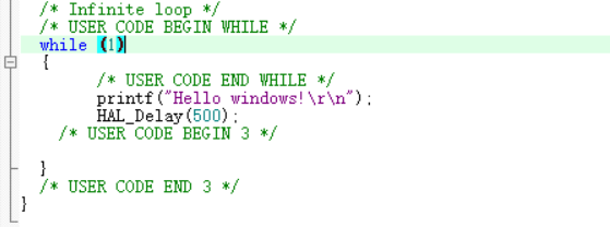
In the main.c main function, add send data
    /* USER CODE END WHILE */
	  	printf("Hello windows!\r\n");
		HAL_Delay(500);
    /* USER CODE BEGIN 3 */
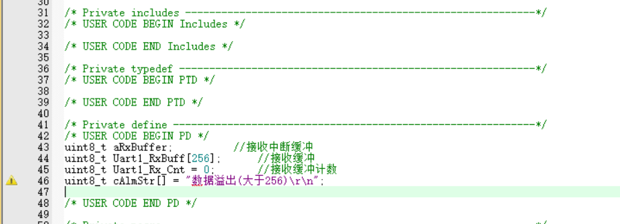
Add the following definition in main.c to receive serial port data
uint8_t aRxBuffer;			//Receive interrupt buffer
uint8_t Uart1_RxBuff[256];		//Receive buffer
uint8_t Uart1_Rx_Cnt = 0;		//Receive buffer count
uint8_t	cAlmStr[] = "data overflow (Greater than 256)\r\n";
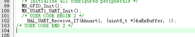
Add a statement that turns on receiving interrupts
/* USER CODE BEGIN 2 */
	HAL_UART_Receive_IT(&huart1, (uint8_t *)&aRxBuffer, 1);
/* USER CODE END 2 */
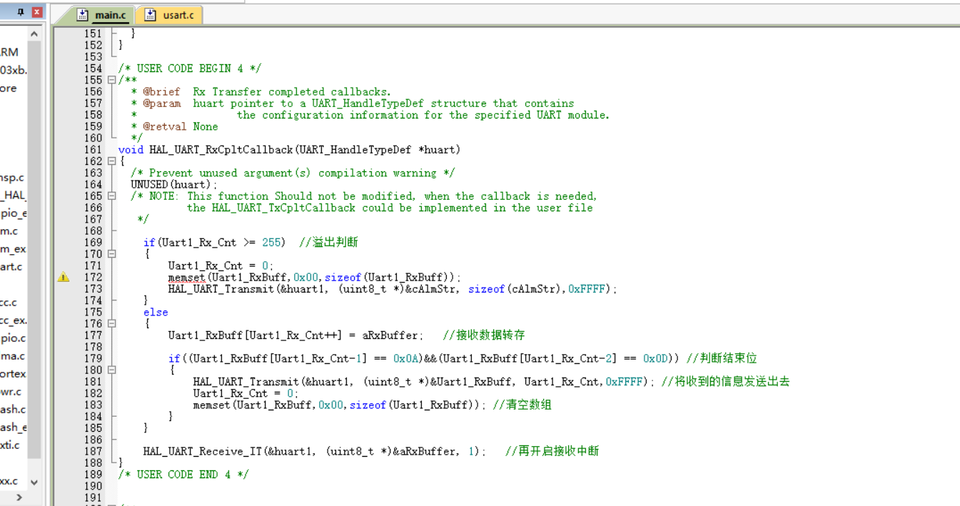
Add interrupt callback function in the lower part of main.c
/* USER CODE BEGIN 4 */
/**
  * @brief  Rx Transfer completed callbacks.
  * @param  huart pointer to a UART_HandleTypeDef structure that contains
  *                the configuration information for the specified UART module.
  * @retval None
  */
void HAL_UART_RxCpltCallback(UART_HandleTypeDef *huart)
{
  /* Prevent unused argument(s) compilation warning */
  UNUSED(huart);
  /* NOTE: This function Should not be modified, when the callback is needed,
           the HAL_UART_TxCpltCallback could be implemented in the user file
   */

	if(Uart1_Rx_Cnt >= 255)  //Overflow judgment
	{
		Uart1_Rx_Cnt = 0;
		memset(Uart1_RxBuff,0x00,sizeof(Uart1_RxBuff));
		HAL_UART_Transmit(&huart1, (uint8_t *)&cAlmStr, sizeof(cAlmStr),0xFFFF);
	}
	else
	{
		Uart1_RxBuff[Uart1_Rx_Cnt++] = aRxBuffer;   //Receive data transfer

		if((Uart1_RxBuff[Uart1_Rx_Cnt-1] == 0x0A)&&(Uart1_RxBuff[Uart1_Rx_Cnt-2] == 0x0D)) //Judgment end bit
		{
			HAL_UART_Transmit(&huart1, (uint8_t *)&Uart1_RxBuff, Uart1_Rx_Cnt,0xFFFF); //Send the received information
			Uart1_Rx_Cnt = 0;
			memset(Uart1_RxBuff,0x00,sizeof(Uart1_RxBuff)); //Empty array
		}
	}

	HAL_UART_Receive_IT(&huart1, (uint8_t *)&aRxBuffer, 1);   //Restart receive interrupt
}
/* USER CODE END 4 */
There are no errors in the compilation, and the warnings can be ignored.
Connect boot0 to 1 and burn it.
3. Serial communication
For communication, boot0 is connected to 0
Communicate with XCOM
3, Serial port sends data to the host computer in DMA mode
1. Engineering setting
For the same new project, select the appropriate chip.
Setting RCC
Set serial port
Enable interrupt
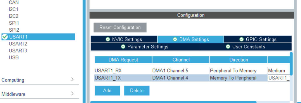
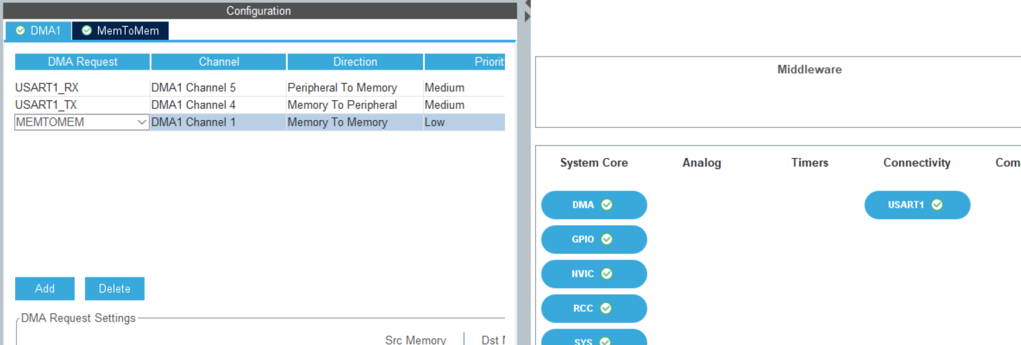
DMA settings
Click Add in DMA Settings to Add a channel, and set the transmission rate to Medium speed
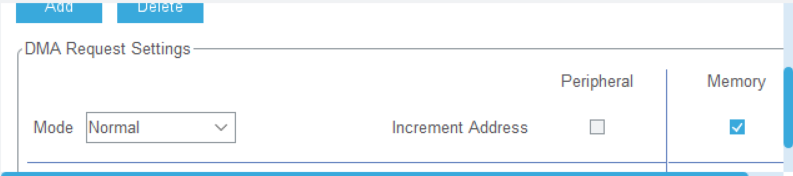
Set the mode to Normal and select Memory on the right
Select DMA under System view
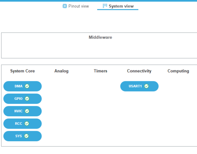
Add MEMTOMEM
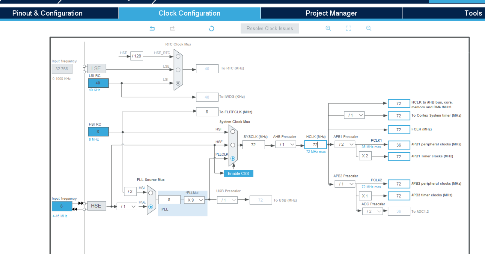
Clock setting
Set to 72
Then export the Keil project file.
2. Code writing
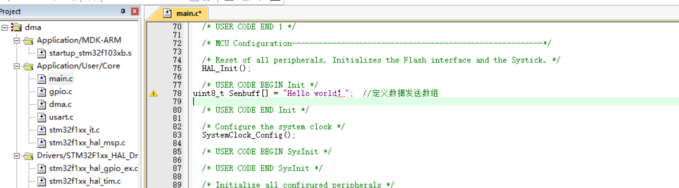
Add code in the main.c file
uint8_t Senbuff[] = "Hello world!"; //Define data sending array
Add the following code:
  HAL_UART_Transmit_DMA(&huart1, (uint8_t *)Senbuff, sizeof(Senbuff));
  HAL_Delay(1000);
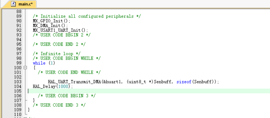
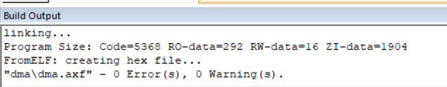
Compile without errors and warnings.
Then burn it.
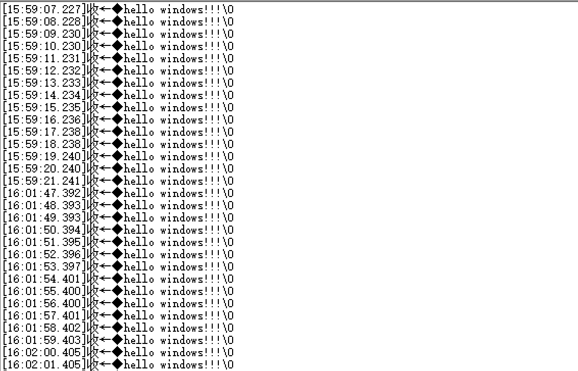
3. Serial port sending data
C8T6 core board boot0 is connected to 0. Open the XCOM serial port assistant and open the serial port to receive signals
4, Personal summary
I learned a lot in this process. Knowing the interrupt mode, you do not have to wait for the data transmission process and the DMA transmission process does not occupy CPU resources. You can run other tasks while transmitting, which is more efficient.
5, References
https://blog.csdn.net/as480133937/article/details/104827639/
https://blog.csdn.net/qq_46467126/article/details/121076618
https://blog.csdn.net/qq_46467126/article/details/121055475