LCD with 8080 timing
There are four control lines of 8080: RD write enable, WR read enable, DC data / command and CS chip selection
8080 bus has many interfaces: 8 / 9 / 16 / 18 bit interface
8080 general timing
Read timing
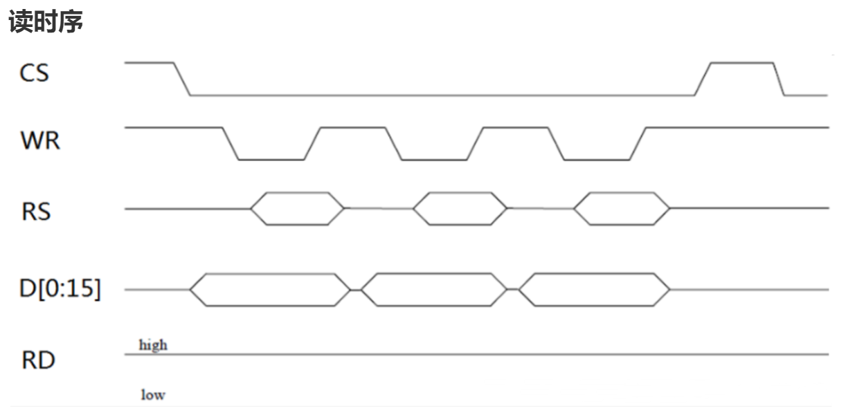
LCD_CS = 0; 		//Film selection
LCD_DC = 1; 		//Read data
LCD_WR = 1; 		//No writing
LCD_RD = 0; 		//Start reading
data = DATAIN();	//Read data
LCD_RD = 1; 		//End reading
LCD_CS = 1; 		//End selection
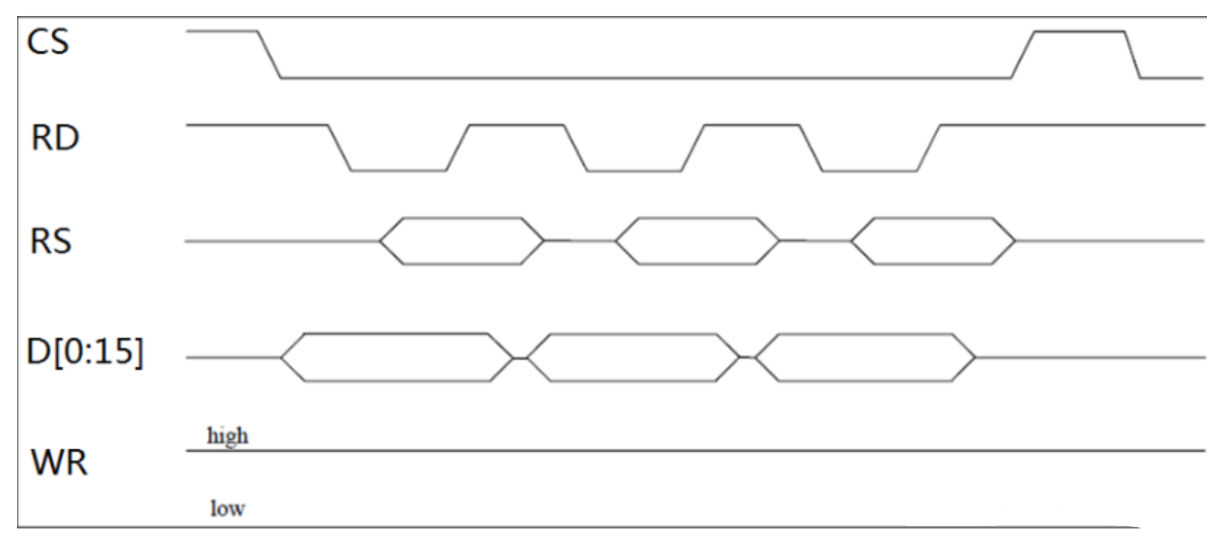
Write timing
DC = 1: write data; DC = 0: write command
Write data:
LCD_CS = 0; 	//Film selection
LCD_RD = 1; 	//No reading
LCD_DC = 1; 	//Write data
DATAOUT(Data); 	//output
LCD_WR = 0; 	//Write start
LCD_WR = 1; 	//Write end
LCD_CS = 1; 	//End selection
Write command:
LCD_CS = 0; 	//Film selection
LCD_RD = 1; 	//No reading
LCD_DC = 0; 	//Write command
DATAOUT(Data); 	//output
LCD_WR = 0; 	//Write start
LCD_WR = 1; 	//Write end
LCD_CS = 1; 	//End selection
Modified timing for ILI9341
Read sequence:
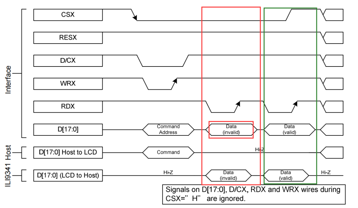
Note: in STM32F1 series products, when GPIO pin works in open drain output mode and reads the value of input data register IDR, the value represented by IDR is the current actual level of GPIO pin. When GPIO pin works in push-pull output mode, reading the value of input IDR cannot obtain the actual level of pin. When reading the level of the data pin, the GPIO must be switched from push-pull output mode to floating input (or open drain output). After reading the data, it can be switched back to the push-pull output mode used to control the LCD most of the time.
uint16_t ILI9341_Read_Data ( void )
{
	uint16_t data;
	//Configure as input mode
 	ILI9341_DATA_PORT->CRL=0X88888888; //Pull up input
	ILI9341_DATA_PORT->CRH=0X88888888; //Pull up input

    //ILI9341_ DATA_ PORT->CRL=0X44444444; // Floating input
    //ILI9341_ DATA_ PORT->CRH=0X44444444; // Floating input

	ILI9341_DATA_PORT->ODR=0X0000;     //Output all 0

	ILI9341_DC_SET;
	ILI9341_WR_SET;

	ILI9341_CS_CLR;
	//Read data
	ILI9341_RD_CLR;

	data=DATAIN;
	ILI9341_RD_SET;
	ILI9341_CS_SET;

	ILI9341_DATA_PORT->CRL=0X33333333; // Push pull output
	ILI9341_DATA_PORT->CRH=0X33333333; // Push pull output
	ILI9341_DATA_PORT->ODR=0XFFFF;     //All output 1
	return data;
}
Note: Generally speaking, the ILI9341 controller will output data only after receiving the command, such as the command to query the controller ID or when reading the pixel value of the LCD screen. When the controller receives the command, the first one it outputs through the 8080 sequence is invalid data, that is, the content represented by "Data(invalid)" in the figure. It is effective output from the second data, that is, "Data(valid)" in the figure.
Write timing:
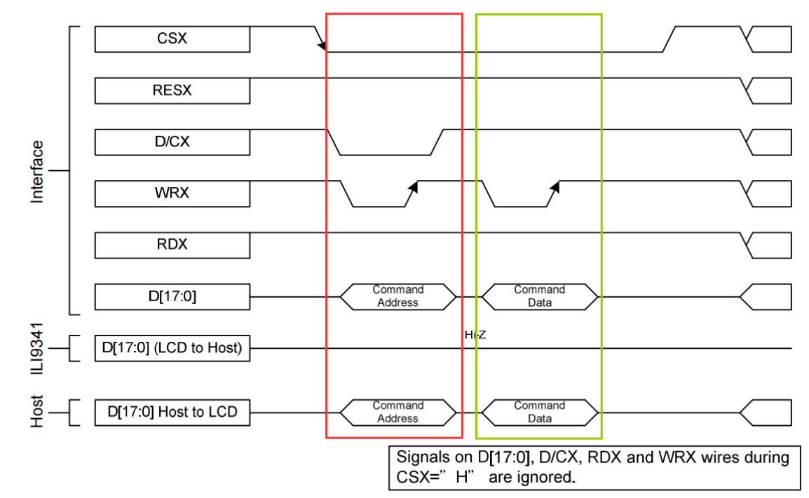
Write command:
__inline void ILI9341_Write_Cmd ( uint16_t usCmd )
{
	ILI9341_CS_CLR;		//Start selection
	ILI9341_DC_CLR;		//Write command
	ILI9341_RD_SET;		//No reading
	DATAOUT(usCmd);		//Output command
	ILI9341_WR_CLR;		//Write start
	ILI9341_WR_SET;		//Write end
	ILI9341_CS_SET;		//End selection
}
Write data:
__inline void ILI9341_Write_Data ( uint16_t usData )
{
	ILI9341_CS_CLR;		//Start selection
	ILI9341_DC_SET;		//Write data
	ILI9341_RD_SET;		//No reading
	DATAOUT(usData);	//output data
	ILI9341_WR_CLR;		//Write start
	ILI9341_WR_SET;		//Write end
	ILI9341_CS_SET;		//End selection
}
This function definition is decorated with "_inline" inline function keyword. Its function can be understood as a macro like "#define". When the program is compiled, the code content in the inline function will be directly added where the function is called. This feature can save the consumption of function call.
Ili9341 here_ Write_ CMD is defined as an inline function in the hope that the program can execute faster.
Using GPIO to simulate 8080 timing data line
Control signal line configuration
//Film selection
#define      ILI9341_CS_CLK                RCC_APB2Periph_GPIOC
#define      ILI9341_CS_PORT               GPIOC
#define      ILI9341_CS_PIN                GPIO_Pin_4

//DC pin
#define      ILI9341_DC_CLK                RCC_APB2Periph_GPIOC
#define      ILI9341_DC_PORT               GPIOC
#define      ILI9341_DC_PIN                GPIO_Pin_7

//Write enable
#define      ILI9341_WR_CLK                RCC_APB2Periph_GPIOC
#define      ILI9341_WR_PORT               GPIOC
#define      ILI9341_WR_PIN                GPIO_Pin_6

//Read enable
#define      ILI9341_RD_CLK                RCC_APB2Periph_GPIOC
#define      ILI9341_RD_PORT               GPIOC
#define      ILI9341_RD_PIN                GPIO_Pin_5

//Backlight pin
#define      ILI9341_BK_CLK                RCC_APB2Periph_GPIOD
#define      ILI9341_BK_PORT               GPIOD
#define      ILI9341_BK_PIN                GPIO_Pin_2

//The reset pin directly uses NRST, and the LCD will be reset when the development board is reset

//Signal line write 1
#define 	 ILI9341_CS_SET   	 ILI9341_ CS_ PORT->BSRR=ILI9341_ CS_ Pin / / chip selection port
#define 	 ILI9341_DC_SET 		 ILI9341_ DC_ PORT->BSRR=ILI9341_ DC_ Pin / / data / command
#define 	 ILI9341_WR_SET 		 ILI9341_ WR_ PORT->BSRR=ILI9341_ WR_ Pin / / write data
#define 	 ILI9341_RD_SET 		 ILI9341_ RD_ PORT->BSRR=ILI9341_ RD_ Pin / / read data

//Signal line write 0
#define 	 ILI9341_CS_CLR   	 ILI9341_ CS_ PORT->BRR=ILI9341_ CS_ Pin / / chip selection port
#define 	 ILI9341_DC_CLR 		 ILI9341_ DC_ PORT->BRR=ILI9341_ DC_ Pin / / data / command
#define 	 ILI9341_WR_CLR 		 ILI9341_ WR_ PORT->BRR=ILI9341_ WR_ Pin / / write data
#define 	 ILI9341_RD_CLR 		 ILI9341_ RD_ PORT->BRR=ILI9341_ RD_ Pin / / read data
Data signal line configuration
#define      ILI9341_DATA_CLK                RCC_APB2Periph_GPIOB
#define      ILI9341_DATA_PORT               GPIOB
#define      ILI9341_DATA_PIN                GPIO_Pin_All

#define DATAOUT(x)  	 ILI9341_ DATA_ PORT->ODR=x; // data output
#define DATAIN      	 ILI9341_ DATA_ PORT->IDR;   // data input
GPIO configuration corresponding to signal line
static void ILI9341_GPIO_Config ( void )
{
	GPIO_InitTypeDef GPIO_InitStructure;
	/* Enable multiplexing IO clock*/
	RCC_APB2PeriphClockCmd ( RCC_APB2Periph_AFIO, ENABLE );
	/* Enable FSMC corresponding pin clock*/
	RCC_APB2PeriphClockCmd (ILI9341_CS_CLK|
                            ILI9341_DC_CLK|
                            ILI9341_WR_CLK|
                            ILI9341_RD_CLK|
                            ILI9341_BK_CLK|
                            ILI9341_DATA_CLK,
                      ENABLE );

    //Turn on SWD and disable jtag (some PB pins are used in jtag interface, and there will be no interference if it is changed to SWD interface)
	GPIO_PinRemapConfig(GPIO_Remap_SWJ_JTAGDisable , ENABLE);

    /* Configure the data line corresponding to the LCD, PORT-D0~D15 */
	GPIO_InitStructure.GPIO_Speed = GPIO_Speed_50MHz;
	GPIO_InitStructure.GPIO_Mode =  GPIO_Mode_Out_PP;

	GPIO_InitStructure.GPIO_Pin = ILI9341_DATA_PIN;
	GPIO_Init ( ILI9341_DATA_PORT, &GPIO_InitStructure );

	GPIO_InitStructure.GPIO_Pin = ILI9341_RD_PIN;
	GPIO_Init (ILI9341_RD_PORT, & GPIO_InitStructure );

	GPIO_InitStructure.GPIO_Pin = ILI9341_WR_PIN;
	GPIO_Init (ILI9341_WR_PORT, & GPIO_InitStructure );

	GPIO_InitStructure.GPIO_Pin = ILI9341_CS_PIN;
	GPIO_Init ( ILI9341_CS_PORT, & GPIO_InitStructure );

	GPIO_InitStructure.GPIO_Pin = ILI9341_DC_PIN;
	GPIO_Init ( ILI9341_DC_PORT, & GPIO_InitStructure );

	/* Configure LCD backlight control pin BLK*/
	GPIO_InitStructure.GPIO_Pin = ILI9341_BK_PIN;
	GPIO_Init ( ILI9341_BK_PORT, &GPIO_InitStructure );
}
Configure ILI9341 related registers
static void ILI9341_REG_Config ( void )
{
	/*  Power control B (CFh)  */
	DEBUG_DELAY();
	ILI9341_Write_Cmd ( 0xCF  );
	ILI9341_Write_Data( 0x00  );
	ILI9341_Write_Data( 0x81  );
	ILI9341_Write_Data( 0x30  );

	/*  Power on sequence control (EDh) */
	DEBUG_DELAY ();
	ILI9341_Write_Cmd ( 0xED );
	ILI9341_Write_Data( 0x64 );
	ILI9341_Write_Data( 0x03 );
	ILI9341_Write_Data( 0x12 );
	ILI9341_Write_Data( 0x81 );

	/*  Driver timing control A (E8h) */
	DEBUG_DELAY ();
	ILI9341_Write_Cmd ( 0xE8 );
	ILI9341_Write_Data( 0x85 );
	ILI9341_Write_Data( 0x10 );
	ILI9341_Write_Data( 0x78 );

	/*  Power control A (CBh) */
	DEBUG_DELAY ();
	ILI9341_Write_Cmd ( 0xCB );
	ILI9341_Write_Data( 0x39 );
	ILI9341_Write_Data( 0x2C );
	ILI9341_Write_Data( 0x00 );
	ILI9341_Write_Data( 0x34 );
	ILI9341_Write_Data( 0x02 );

	/* Pump ratio control (F7h) */
	DEBUG_DELAY ();
	ILI9341_Write_Cmd ( 0xF7 );
	ILI9341_Write_Data ( 0x20 );

	/* Driver timing control B */
	DEBUG_DELAY ();
	ILI9341_Write_Cmd ( 0xEA );
	ILI9341_Write_Data( 0x00 );
	ILI9341_Write_Data( 0x00 );

	/* Frame Rate Control (In Normal Mode/Full Colors) (B1h) */
	DEBUG_DELAY ();
	ILI9341_Write_Cmd ( 0xB1 );
	ILI9341_Write_Data( 0x00 );
	ILI9341_Write_Data( 0x1B );

	/*  Display Function Control (B6h) */
	DEBUG_DELAY ();
	ILI9341_Write_Cmd ( 0xB6 );
	ILI9341_Write_Data( 0x0A );
	ILI9341_Write_Data( 0xA2 );

	/* Power Control 1 (C0h) */
	DEBUG_DELAY ();
	ILI9341_Write_Cmd ( 0xC0 );
	ILI9341_Write_Data( 0x35 );

	/* Power Control 2 (C1h) */
	DEBUG_DELAY ();
	ILI9341_Write_Cmd ( 0xC1 );
	ILI9341_Write_Data( 0x11 );

	/* VCOM Control 1 (C5h) */
	ILI9341_Write_Cmd ( 0xC5 );
	ILI9341_Write_Data( 0x45 );
	ILI9341_Write_Data( 0x45 );

	/*  VCOM Control 2 (C7h)  */
	ILI9341_Write_Cmd ( 0xC7 );
	ILI9341_Write_Data( 0xA2 );

	/* Enable 3G (F2h) */
	ILI9341_Write_Cmd ( 0xF2 );
	ILI9341_Write_Data( 0x00 );

	/* Gamma Set (26h) */
	ILI9341_Write_Cmd ( 0x26 );
	ILI9341_Write_Data( 0x01 );
	DEBUG_DELAY ();

	/* Positive Gamma Correction */
	ILI9341_Write_Cmd ( 0xE0 ); //Set Gamma
	ILI9341_Write_Data ( 0x0F );
	ILI9341_Write_Data ( 0x26 );
	ILI9341_Write_Data ( 0x24 );
	ILI9341_Write_Data ( 0x0B );
	ILI9341_Write_Data ( 0x0E );
	ILI9341_Write_Data ( 0x09 );
	ILI9341_Write_Data ( 0x54 );
	ILI9341_Write_Data ( 0xA8 );
	ILI9341_Write_Data ( 0x46 );
	ILI9341_Write_Data ( 0x0C );
	ILI9341_Write_Data ( 0x17 );
	ILI9341_Write_Data ( 0x09 );
	ILI9341_Write_Data ( 0x0F );
	ILI9341_Write_Data ( 0x07 );
	ILI9341_Write_Data ( 0x00 );

	/* Negative Gamma Correction (E1h) */
	ILI9341_Write_Cmd ( 0XE1 ); //Set Gamma
	ILI9341_Write_Data ( 0x00 );
	ILI9341_Write_Data ( 0x19 );
	ILI9341_Write_Data ( 0x1B );
	ILI9341_Write_Data ( 0x04 );
	ILI9341_Write_Data ( 0x10 );
	ILI9341_Write_Data ( 0x07 );
	ILI9341_Write_Data ( 0x2A );
	ILI9341_Write_Data ( 0x47 );
	ILI9341_Write_Data ( 0x39 );
	ILI9341_Write_Data ( 0x03 );
	ILI9341_Write_Data ( 0x06 );
	ILI9341_Write_Data ( 0x06 );
	ILI9341_Write_Data ( 0x30 );
	ILI9341_Write_Data ( 0x38 );
	ILI9341_Write_Data ( 0x0F );

	/* memory access control set */
	DEBUG_DELAY ();
	ILI9341_Write_Cmd ( 0x36 );
	ILI9341_Write_Data ( 0xC8 );    /*Scanning mode from the upper left corner (starting point) to the lower right corner (end point) of the vertical screen*/
	DEBUG_DELAY ();

	/* column address control set */
	ILI9341_Write_Cmd ( CMD_SetCoordinateX );
	ILI9341_Write_Data ( 0x00 );
	ILI9341_Write_Data ( 0x00 );
	ILI9341_Write_Data ( 0x00 );
	ILI9341_Write_Data ( 0xEF );

	/* page address control set */
	DEBUG_DELAY ();
	ILI9341_Write_Cmd ( CMD_SetCoordinateY );
	ILI9341_Write_Data ( 0x00 );
	ILI9341_Write_Data ( 0x00 );
	ILI9341_Write_Data ( 0x01 );
	ILI9341_Write_Data ( 0x3F );

	/*  Pixel Format Set (3Ah)  */
	DEBUG_DELAY ();
	ILI9341_Write_Cmd ( 0x3a );
	ILI9341_Write_Data ( 0x55 );

	/* Sleep Out (11h)  */
	ILI9341_Write_Cmd ( 0x11 );
	ILI9341_Delay ( 0xAFFf<<2 );
	DEBUG_DELAY ();

	/* Display ON (29h) */
	ILI9341_Write_Cmd ( 0x29 );

}
The codes and parameters sent in the initialization process are mainly configured with the power on process of the LCD screen, the gamma parameters of the display screen, resolution, pixel format and so on.
LCD initialization
void ILI9341_Init ( void )
{
	ILI9341_GPIO_Config ();					//Configure IO port
	ILI9341_BackLed_Control ( ENABLE );     //Turn on the LCD backlight
	ILI9341_REG_Config ();					//Configure LCD related registers
	ILI9341_GramScan(6);					//Set the default scanning direction, where 6 mode is the default display direction of most LCD routines
}
Get the chip ID of LCD
uint16_t ILI9341_Read_ID(void)
{
	uint16_t id = 0;
	ILI9341_Write_Cmd(0xD3);
	ILI9341_Read_Data();
	ILI9341_Read_Data();
	id = ILI9341_Read_Data();
	id<<=8;
	id|=ILI9341_Read_Data();
	return id;
}
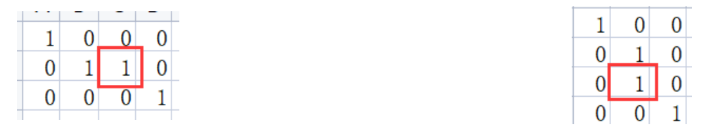
Set scan direction
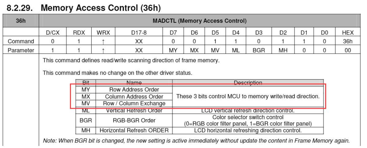
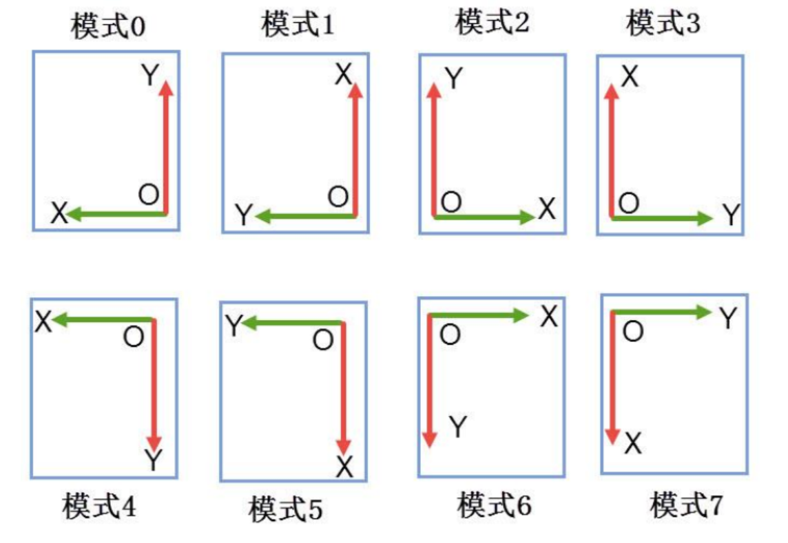
It can be seen from the above figure that the scanning direction of GRAM is configured by configuring MY, MX and MV.
The specific process is as follows:
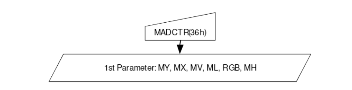
ILI9341_Write_Cmd ( 0x36 );
ILI9341_Write_Data ( 0x08 |(ucOption<<5));	//Start BGR and write the values of MY, MX and MV to the high order. There are 8 modes
8 scanning modes: (mode 6 is the most suitable for our reading habits. The scanning direction is consistent with the text direction, from left to right and from top to bottom)
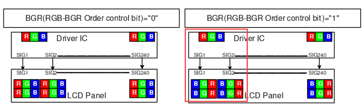
BGR is enabled in the code, that is, RGB is turned into BGR. The effect is as follows:
Set the scanning direction function of LCD
void ILI9341_GramScan ( uint8_t ucOption )
{
	//Parameter check, only 0-7 can be entered
	if(ucOption >7 )
		return;
	//Update LCD according to mode_ SCAN_ The value of mode is mainly used to select calculation parameters on the touch screen
	LCD_SCAN_MODE = ucOption;

	//Updates the pixel width in the XY direction according to the mode
	if(ucOption%2 == 0)
	{
		//In 0 2 4 6 mode, the pixel width in X direction is 240 and that in Y direction is 320
		LCD_X_LENGTH = ILI9341_LESS_PIXEL;
		LCD_Y_LENGTH =	ILI9341_MORE_PIXEL;
	}
	else
	{
		//In 1 3 5 7 mode, the pixel width in X direction is 320 and that in Y direction is 240
		LCD_X_LENGTH = ILI9341_MORE_PIXEL;
		LCD_Y_LENGTH =	ILI9341_LESS_PIXEL;
	}

	//0x36 the upper 3 bits of the command parameter can be used to set the GRAM scanning direction
	ILI9341_Write_Cmd ( 0x36 );
	ILI9341_Write_Data( 0x08 |(ucOption<<5));//Set LCD parameters according to the value of ucOption, with a total of 0-7 modes

    ILI9341_Write_Cmd ( 0x2A );
	ILI9341_Write_Data( 0x00 );							/* x Starting coordinate height 8 bits */
	ILI9341_Write_Data( 0x00 );							/* x Lower 8 bits of starting coordinate */
	ILI9341_Write_Data( ((LCD_X_LENGTH-1)>>8)&0xFF ); 	/* x End coordinate height 8 bits */
	ILI9341_Write_Data( (LCD_X_LENGTH-1)&0xFF );		/* x End coordinate lower 8 bits */

	ILI9341_Write_Cmd ( 0x2B );
	ILI9341_Write_Data ( 0x00 );						/* y Starting coordinate height 8 bits */
	ILI9341_Write_Data ( 0x00 );						/* y Lower 8 bits of starting coordinate */
	ILI9341_Write_Data ( ((LCD_Y_LENGTH-1)>>8)&0xFF );	/* y End coordinate height 8 bits */
	ILI9341_Write_Data ( (LCD_Y_LENGTH-1)&0xFF );		/* y End coordinate lower 8 bits */

	/* write gram start */
	ILI9341_Write_Cmd ( 0x2C );
}
Fill pixels
According to the flow chart provided in the data manual:
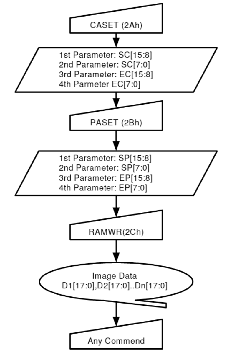
First write the command 0x2A to configure the start address, then write the command 0x2B to configure the end address, and finally write 0x2C to fill a specific number of pixels with a specific color.
void ILI9341_FillColor(uint16_t X0, uint16_t Y0,
                       uint16_t Width, uint16_t Height,
                       uint32_t ulAmout_Point, uint16_t usColor)
{
    uint32_t i = 0;
	ILI9341_Write_Cmd (0x2A); 								/* Set X coordinate */
	ILI9341_Write_Data ( X0 >> 8  );	 					/* First 8 bits high, then 8 bits low */
	ILI9341_Write_Data ( X0 & 0xff  );	 					/* Set start and end points*/
	ILI9341_Write_Data ( ( X0 + Width - 1 ) >> 8  );
	ILI9341_Write_Data ( ( X0 + Width - 1 ) & 0xff);

	ILI9341_Write_Cmd (0x2B); 			    				/* Set Y coordinate*/
	ILI9341_Write_Data ( Y0 >> 8  );
	ILI9341_Write_Data ( Y0 & 0xff  );
	ILI9341_Write_Data ( ( Y0 + Height - 1 ) >> 8 );
	ILI9341_Write_Data ( ( Y0 + Height - 1) & 0xff);

	ILI9341_Write_Cmd (0x2C);								/* memory write */
	for ( i = 0; i < ulAmout_Point; i ++ )
		ILI9341_Write_Data ( usColor );

}


//Or separate as follows
void ILI9341_OpenWindow ( uint16_t usX, uint16_t usY, uint16_t usWidth, uint16_t usHeight )
{
    ILI9341_Write_Cmd ( CMD_SetCoordinateX ); 	/* Set X coordinate */
    ILI9341_Write_Data ( usX >> 8  );	 		/* First 8 bits high, then 8 bits low */
    ILI9341_Write_Data ( usX & 0xff  );	 		/* Set start and end points*/
    ILI9341_Write_Data ( ( usX + usWidth - 1 ) >> 8  );
    ILI9341_Write_Data ( ( usX + usWidth - 1 ) & 0xff  );

    ILI9341_Write_Cmd ( CMD_SetCoordinateY ); 			     /* Set Y coordinate*/
    ILI9341_Write_Data ( usY >> 8  );
    ILI9341_Write_Data ( usY & 0xff  );
    ILI9341_Write_Data ( ( usY + usHeight - 1 ) >> 8 );
    ILI9341_Write_Data ( ( usY + usHeight - 1) & 0xff );
}

static __inline void ILI9341_FillColor ( uint32_t ulAmout_Point, uint16_t usColor )
{
    uint32_t i = 0;
    /* memory write */
    ILI9341_Write_Cmd ( CMD_SetPixel );
    for ( i = 0; i < ulAmout_Point; i ++ )
        ILI9341_Write_Data ( usColor );
}
give an example:
If a window with X0=10, Y0=30, Width=50 and Height=20 is set, and then 50 * 20 pixel data with color value of 0xfff are filled continuously, a white rectangle with width of 50 pixels and height of 20 pixels can be displayed at the starting coordinates of (10,30).
Screen clearing function
Directly open a full screen window and write the background color.
void ILI9341_Clear ( uint16_t usX, uint16_t usY, uint16_t usWidth, uint16_t usHeight )
{
	ILI9341_OpenWindow ( usX, usY, usWidth, usHeight );
	ILI9341_FillColor ( usWidth * usHeight, CurrentBackColor );
}
Draw line segments
Using the previous function of drawing pixels, you can draw various graphics, and draw a line segment here.
General principle:
-
Determine the drawing position of the line segment according to the starting point and end point of the line segment to be drawn;
-
Take out the X and y coordinates of the starting point and the ending point, the starting point (x1,y1) and the ending point (x0,y0);
-
Judge the direction of the line segment, (x1 - x0 = 0) is the vertical line, and (y1 - y0 = 0) is the horizontal line
If (x1 - x0) > (y1 - y0), it indicates that the inclination angle of the line segment to the horizontal line is less than 45 °, then add an increment on the X axis;
If (x1 - x0) < (y1 - y0), it indicates that the inclination angle of the line segment to the horizontal line is greater than 45 °, then add an increment on the y axis;x-axis increment: y-axis increment:
-
Determine the size of each increment according to (x1 - x0) and (y1 - y0). For example, (x1 - x0) - (y1 - y0) = 1, then the increment of X axis is 2 on each corresponding y coordinate;
-
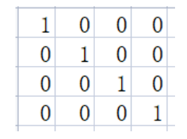
Special case: (x1 - x0) = (y1 - y0), as long as the pixel points are incremented by one pixel point each time on the x-axis and y-axis, as shown in the following figure:
//Here is the line drawing function of wildfire
/**
 * @brief  Use Bresenham algorithm to draw line segments on ILI9341 display
 * @param  usX1 : The X coordinate of the starting point of the line segment in a specific scanning direction
 * @param  usY1 : Y coordinate of the starting point of the line segment in a specific scanning direction
 * @param  usX2 : The X coordinate of the end point of the line segment in a specific scanning direction
 * @param  usY2 : Y coordinate of the end point of the line segment in a specific scanning direction
 * @note   LCD can be used_ SetBackColor,LCD_SetTextColor,LCD_SetColors function sets the color
 * @retval nothing
 */
void ILI9341_DrawLine ( uint16_t usX1, uint16_t usY1, uint16_t usX2, uint16_t usY2 )
{
    uint16_t us;
    uint16_t usX_Current, usY_Current;

    int32_t lError_X = 0, lError_Y = 0, lDelta_X, lDelta_Y, lDistance;
    int32_t lIncrease_X, lIncrease_Y;

    lDelta_X = usX2 - usX1; //Calculate coordinate increment
    lDelta_Y = usY2 - usY1;

    usX_Current = usX1;
    usY_Current = usY1;

    if ( lDelta_X > 0 )
        lIncrease_X = 1; //Set single step direction
    else if ( lDelta_X == 0 )
        lIncrease_X = 0;//Vertical line
    else
    {
        lIncrease_X = -1;
        lDelta_X = - lDelta_X;
    }

    if ( lDelta_Y > 0 )
        lIncrease_Y = 1;

    else if ( lDelta_Y == 0 )
        lIncrease_Y = 0;//level
    else
    {
        lIncrease_Y = -1;
        lDelta_Y = - lDelta_Y;
    }

    if (  lDelta_X > lDelta_Y )
        lDistance = lDelta_X; //Select basic incremental axis
    else
        lDistance = lDelta_Y;

    for ( us = 0; us <= lDistance + 1; us ++ )//Draw line output
    {
        ILI9341_SetPointPixel ( usX_Current, usY_Current );//Draw points
        lError_X += lDelta_X ;
        lError_Y += lDelta_Y ;

        if ( lError_X > lDistance )
        {
            lError_X -= lDistance;
            usX_Current += lIncrease_X;
        }

        if ( lError_Y > lDistance )
        {
            lError_Y -= lDistance;
            usY_Current += lIncrease_Y;
        }
    }
}
Draw graphics
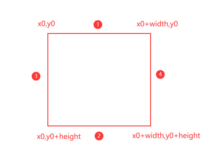
The following is to draw a rectangle. Use the relationship between coordinates and line segment length to draw a hollow or solid rectangle. Other graphics can also be drawn on this basis. However, drawing a circle is a little more troublesome.
Coordinate definition diagram of rectangle:
void ILI9341_DrawRectangle ( uint16_t X_Start,
                             uint16_t Y_Start,
                             uint16_t Width,
                             uint16_t Height,
                             uint8_t Filled )
{
    if ( Filled )	//Solid rectangle
    {
        ILI9341_OpenWindow ( X_Start, Y_Start, Width, Height );
        ILI9341_FillColor ( Width * Height ,CurrentTextColor);
    }
    else			//hollow rectangle
    {
        ILI9341_DrawLine ( X_Start, Y_Start, X_Start + Width - 1, Y_Start );	//1

        ILI9341_DrawLine ( X_Start,
                           Y_Start + Height - 1,
                           X_Start + Width - 1,
                           Y_Start + Height - 1 );		//2

        ILI9341_DrawLine ( X_Start, Y_Start, X_Start, Y_Start + Height - 1 );	//3

        ILI9341_DrawLine ( X_Start + Width - 1,
                           Y_Start,
                           X_Start + Width - 1,
                           Y_Start + Height - 1 );		//4
    }
}
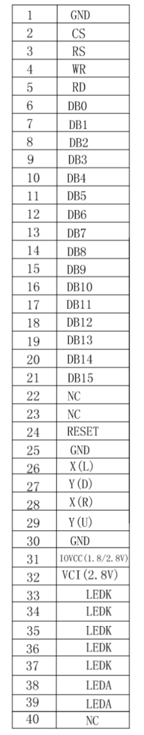
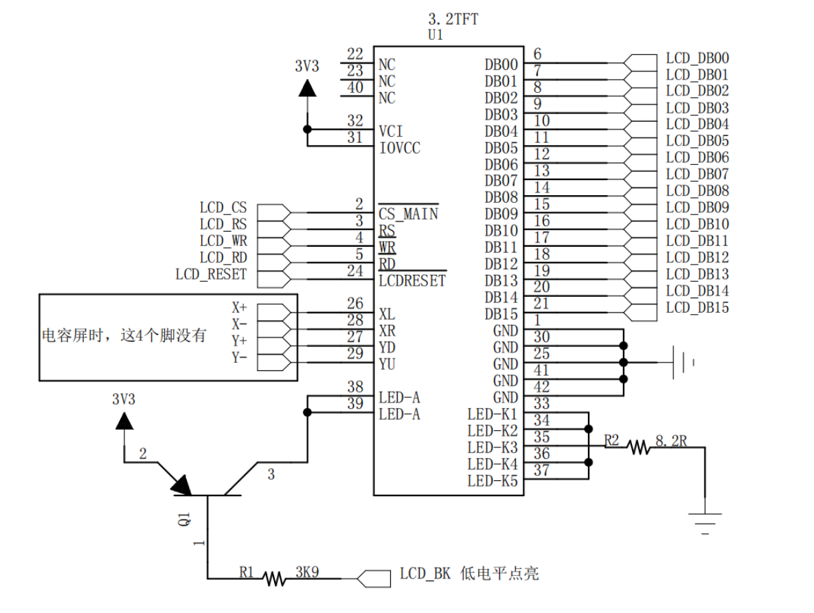
hardware interface
The following is the 40pin LCD hardware interface
Hardware wiring diagram
General process:
1. The LCD shall be configured with data line and control line first, that is, GPIO configuration;
2. Then turn on the backlight of LCD;
3. Reconfigure relevant registers;
4. Finally determine the scanning direction of GRAM;
5. Initialize and clear the screen in the main function;
6. Then you can use various drawing functions to draw graphics.