STM32 learning from scratch @EnzoReventon
SPI read / write FLASH
Related links:
Introduction to SPI physical layer and FLASH chip
SPI protocol layer
SPI features and architecture
reference material:
[wildfire EmbedFire] practical guide for STM32 Library Development -- Based on wildfire Decepticon development board
[punctual atom] STM32F4 Development Guide - library function version_ V1. two
[ST] STM32F4xx Chinese Reference Manual
Introduction to SPI protocol and bus protocol
W25Q128 product data manual
1. Realize functions
- Realize the erasure of FLASH sector
- Write data to the FLASH sector, read the data, and debug and observe through the serial port debugging assistant
- Write 256 data and read the written data and the remaining unwritten data.
- All data in this sector is written.
2 hardware design
The peripherals used in this paper are SPI1 (punctual atom F4 Explorer development board), FLASH and USART1.
USART is used to debug programs. We still use USART1, so connect PB9 and PB10 with TX and RX.
Check the hardware manual of F4 Explorer development board of punctual atom to understand the correspondence between SPI pin and GPIO.
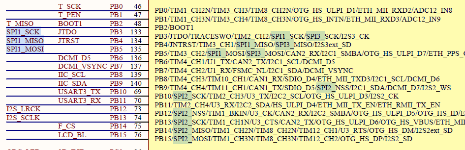
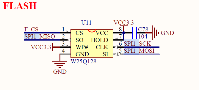
It can be seen from the above figure that the SCK, MISO and MOSI of SPI are respectively connected with PB3, PB4 and PB5 of the chip, and the chip selection signal F_CS is connected with PB14, so it is necessary to pay attention not to configure the wrong pin during the later program configuration.
Software design process 3
① Enable SPIx and IO port clock
RCC_AHBxPeriphClockCmd() / RCC_APBxPeriphClockCmd();
② Initialize IO port as multiplexing function
void GPIO_Init(GPIO_TypeDef* GPIOx, GPIO_InitTypeDef* GPIO_InitStruct);
③ Set pin multiplexing mapping:
GPIO_PinAFConfig();
② Initialize SPIx and set SPIx working mode
void SPI_Init(SPI_TypeDef* SPIx, SPI_InitTypeDef* SPI_InitStruct);
③ Enable SPIx
void SPI_Cmd(SPI_TypeDef* SPIx, FunctionalState NewState);
④ Write byte sending function: uint8_t SPI_FLASH_ByteWrite(uint8_t data)
Send data (instruction): void SPI_I2S_SendData(SPI_TypeDef* SPIx, uint16_t Data);
Receive returned data: uint16_t SPI_I2S_ReceiveData(SPI_TypeDef* SPIx) ;
⑤ Write erase sector function: void SPI_FLASH_Erase_Sector(uint32_t addr);
⑥ Write data function: void SPI_FLASH_Page_Write(uint32_t addr, uint8_t *buf, uint32_t size);
⑦ Write read data function: void SPI_FLASH_Read_Buff(uint32_t addr, uint8_t *buf, uint32_t size);
⑧ View SPI transmission status
SPI_I2S_GetFlagStatus(SPI2, SPI_I2S_FLAG_RXNE);
⑨ Write SPI sending function
Control chip selection pin: GPIO_ResetBits(),GPIO_SetBits();
⑩ Main function call, optimization program (timeout function, macro definition, waiting for idle function, write enable function)
4 code analysis
- Macro definition
Here you can define according to your own needs and programming habits. The advantage of macro definition is to facilitate the transplantation and modification of the program.
/*Command definition - beginning*/
#define W25X_WriteEnable		      		0x06
#define W25X_WriteDisable		     		0x04
#define W25X_ReadStatusReg		      		0x05
#define W25X_WriteStatusReg		      		0x01
#define W25X_ReadData			      		0x03
#define W25X_FastReadData		      		0x0B
#define W25X_FastReadDual		      		0x3B
#define W25X_PageProgram		      		0x02
#define W25X_BlockErase			      		0xD8
#define W25X_SectorErase		      		0x20
#define W25X_ChipErase			      		0xC7
#define W25X_PowerDown			      		0xB9
#define W25X_ReleasePowerDown	      		0xAB
#define W25X_DeviceID			      		0xAB
#define W25X_ManufactDeviceID   	  		0x90
#define W25X_JedecDeviceID		      		0x9F

/*SPI GPIO Interface*/
#define FLASH_SPI                          	SPI1
#define FLASH_SPI_CLK                       RCC_APB2Periph_SPI1
#define FLASH_SPI_CLK_INIT					RCC_APB2PeriphClockCmd

#define FLASH_SPI_SCK_PIN                  	GPIO_Pin_3
#define FLASH_SPI_SCK_GPIO_PORT            	GPIOB
#define FLASH_SPI_SCK_GPIO_CLK             	RCC_AHB1Periph_GPIOB
#define FLASH_SPI_SCK_SOURCE               	GPIO_PinSource3
#define FLASH_SPI_SCK_AF                   	GPIO_AF_SPI1

#define FLASH_SPI_MOSI_PIN                  GPIO_Pin_5
#define FLASH_SPI_MOSI_GPIO_PORT            GPIOB
#define FLASH_SPI_MOSI_GPIO_CLK             RCC_AHB1Periph_GPIOB
#define FLASH_SPI_MOSI_SOURCE               GPIO_PinSource5
#define FLASH_SPI_MOSI_AF                   GPIO_AF_SPI1

#define FLASH_SPI_MISO_PIN                  GPIO_Pin_4
#define FLASH_SPI_MISO_GPIO_PORT            GPIOB
#define FLASH_SPI_MISO_GPIO_CLK             RCC_AHB1Periph_GPIOB
#define FLASH_SPI_MISO_SOURCE               GPIO_PinSource4
#define FLASH_SPI_MISO_AF                   GPIO_AF_SPI1

#define FLASH_SPI_CS_PIN                  	GPIO_Pin_14
#define FLASH_SPI_CS_GPIO_PORT           	GPIOB
#define FLASH_SPI_CS_GPIO_CLK             	RCC_AHB1Periph_GPIOB

#define FLASH_SPI_CS_LOW()					GPIO_ResetBits(FLASH_SPI_CS_GPIO_PORT,FLASH_SPI_CS_PIN)
#define FLASH_SPI_CS_HIGH()					GPIO_SetBits(FLASH_SPI_CS_GPIO_PORT,FLASH_SPI_CS_PIN)

/*Wait timeout*/
#define SPIT_FLAG_TIMEOUT         			((uint32_t)0x1000)
#define SPIT_LONG_TIMEOUT         			((uint32_t)(10 * SPIT_FLAG_TIMEOUT))
- Function declaration
/*Function declaration*/

static void SPI_GPIO_Config(void);										//Pin initialization function
void SPI_Mode_Config(void);												//SPI mode initialization function
void SPI_FLASH_Init(void);												//SPI FLASH peripheral initialization calling function
uint8_t SPI_FLASH_ByteWrite(uint8_t data);								//Byte write function
uint8_t SPI_FLASH_Read_ID(void);										//SPI read FLASH ID function
void SPI_FLASH_Erase_Sector(uint32_t addr);								//FLASH erase function
void SPI_FLASH_Write_Enable(void);										//SPI write enable function
void SPI_FLASH_Wait_For_Standby(void);									//SPI wait until idle function
void SPI_FLASH_Read_Buff(uint32_t addr, uint8_t *buf, uint32_t size);	//SPI continuous reading function
void SPI_FLASH_Write_Buff(uint32_t addr, uint8_t *buf, uint32_t size);	//SPI continuous write function
void SPI_FLASH_Page_Write(uint32_t addr, uint8_t *buf, uint32_t size);	//SPI page write function
SPI subfunction:
- Static function declaration:
//Declare timeout variable
static uint32_t SPITimeOut = ((uint32_t)(10 * SPIT_FLAG_TIMEOUT));

//Declare error code return function
static uint32_t SPI_TIMEOUT_UserCallback(uint8_t errorCode);
- SPI GPIO initialization multiplexing function
/*
================================================
SPI GPIO Initialize multiplexing function
================================================
*/
static void SPI_GPIO_Config(void)
{

		  GPIO_InitTypeDef  GPIO_InitStructure;

		  FLASH_SPI_CLK_INIT(FLASH_SPI_CLK, ENABLE);				//Enable SPI clock RCC_APB2PeriphClockCmd(RCC_APB2Periph_SPI1)

																	/* Enable FLASH_SPI and GPIO clock */
																  /*!< SPI_FLASH_SPI_CS_GPIO, SPI_FLASH_SPI_MOSI_GPIO,
																       SPI_FLASH_SPI_MISO_GPIO,SPI_FLASH_SPI_SCK_GPIO Clock enable */

		  RCC_AHB1PeriphClockCmd(FLASH_SPI_SCK_GPIO_CLK | FLASH_SPI_MOSI_GPIO_CLK|
								FLASH_SPI_MISO_GPIO_CLK|FLASH_SPI_CS_GPIO_CLK, ENABLE);					//Initialize GPIO clock
		  //Check pin, initialize SCK,MOSI,MISO,CS pin and GPIO
		  //Set pin reuse
		  GPIO_PinAFConfig(FLASH_SPI_SCK_GPIO_PORT, FLASH_SPI_SCK_SOURCE, FLASH_SPI_SCK_AF);
		  GPIO_PinAFConfig(FLASH_SPI_MOSI_GPIO_PORT, FLASH_SPI_MOSI_SOURCE, FLASH_SPI_MOSI_AF);
		  GPIO_PinAFConfig(FLASH_SPI_MISO_GPIO_PORT, FLASH_SPI_MISO_SOURCE, FLASH_SPI_MISO_AF);

			/*!< Configure SPI_FLASH_SPI pin: SCK */
		  GPIO_InitStructure.GPIO_Pin = FLASH_SPI_SCK_PIN;
		  GPIO_InitStructure.GPIO_Mode = GPIO_Mode_AF;
		  GPIO_InitStructure.GPIO_Speed = GPIO_Speed_50MHz;
		  GPIO_InitStructure.GPIO_OType = GPIO_OType_PP;
		  GPIO_InitStructure.GPIO_PuPd  = GPIO_PuPd_NOPULL;
		  GPIO_Init(FLASH_SPI_SCK_GPIO_PORT, &GPIO_InitStructure);

			/*!< Configure SPI_FLASH_SPI pin: MISO */
		  GPIO_InitStructure.GPIO_Pin = FLASH_SPI_MOSI_PIN;
		  GPIO_Init(FLASH_SPI_MOSI_GPIO_PORT, &GPIO_InitStructure);

			/*!< Configure SPI_FLASH_SPI pin: MOSI */
		  GPIO_InitStructure.GPIO_Pin = FLASH_SPI_MISO_PIN;
		  GPIO_Init(FLASH_SPI_MOSI_GPIO_PORT, &GPIO_InitStructure);

			/*!< Configure SPI_FLASH_SPI pin: CS */
		  GPIO_InitStructure.GPIO_Pin = GPIO_Pin_14;
		  GPIO_InitStructure.GPIO_Mode = GPIO_Mode_OUT;
		  GPIO_InitStructure.GPIO_Speed = GPIO_Speed_50MHz;
		  GPIO_InitStructure.GPIO_OType = GPIO_OType_PP;
		  GPIO_InitStructure.GPIO_PuPd  = GPIO_PuPd_NOPULL;
		  GPIO_Init(FLASH_SPI_CS_GPIO_PORT, &GPIO_InitStructure);

}

/*
================================================
SPI Initialization structure initialization
================================================
*/
void SPI_Mode_Config(void)
{
		/*!< Initialize SPI structure function */
		SPI_InitTypeDef		SPI_InitStructure;

		SPI_InitStructure.SPI_BaudRatePrescaler=SPI_BaudRatePrescaler_2;
		SPI_InitStructure.SPI_CPHA=SPI_CPHA_1Edge;
		SPI_InitStructure.SPI_CPOL=SPI_CPOL_Low;
		SPI_InitStructure.SPI_CRCPolynomial=7;
		SPI_InitStructure.SPI_DataSize=SPI_DataSize_8b;
		SPI_InitStructure.SPI_Direction=SPI_Direction_2Lines_FullDuplex;
		SPI_InitStructure.SPI_FirstBit=SPI_FirstBit_MSB;
		SPI_InitStructure.SPI_Mode=SPI_Mode_Master;
		SPI_InitStructure.SPI_NSS=SPI_NSS_Soft;

		SPI_Init(FLASH_SPI,&SPI_InitStructure);

		SPI_Cmd(FLASH_SPI,ENABLE);

}
- SPI FLASH peripheral initialization
================================================
SPI FLASH Peripheral initialization
================================================
*/
void SPI_FLASH_Init(void)
{
  SPI_GPIO_Config();

  SPI_Mode_Config();
}
- SPI byte write
/*
================================================
Send a byte via SPI
 Parameter: data to be written
 Return value: error code
================================================
*/
uint8_t SPI_FLASH_ByteWrite(uint8_t data)
{
	uint8_t re_data;

	//Wait for TXE flag
	SPITimeOut = SPIT_FLAG_TIMEOUT;
  while(SPI_I2S_GetFlagStatus (FLASH_SPI, SPI_I2S_FLAG_TXE) == RESET )
  {
    if((SPITimeOut--) == 0) return SPI_TIMEOUT_UserCallback(1);
  }

	SPI_I2S_SendData(FLASH_SPI, data);

	//Wait for the RXNE flag to confirm the completion of transmission and prepare to read data
	SPITimeOut = SPIT_FLAG_TIMEOUT;
	while(SPI_I2S_GetFlagStatus (FLASH_SPI, SPI_I2S_FLAG_RXNE) == RESET )
  {
    if((SPITimeOut--) == 0) return SPI_TIMEOUT_UserCallback(2);
  }

	re_data = SPI_I2S_ReceiveData(FLASH_SPI);

	return re_data;
}
- Read FLASH ID
/*
================================================
Read ID0-ID7
================================================
*/

uint8_t SPI_FLASH_Read_ID(void)
{
uint8_t id;
	//Control chip selection pin
	FLASH_SPI_CS_LOW();

	//Instruction code
	SPI_FLASH_ByteWrite(W25X_ReleasePowerDown);

	SPI_FLASH_ByteWrite(0xFF);
	SPI_FLASH_ByteWrite(0xFF);
	SPI_FLASH_ByteWrite(0xFF);

	//Receive read content

	id = SPI_FLASH_ByteWrite(0xFF);
	FLASH_SPI_CS_HIGH();
	return id;

}
- Erase FLASH sector function
/*
================================================
Erase sector
addr:Must be aligned to the first address of the sector to be erased
================================================
*/

void SPI_FLASH_Erase_Sector(uint32_t addr)
{
	//Write enable
	SPI_FLASH_Write_Enable();


	//Control chip selection pin
	FLASH_SPI_CS_LOW();

	//Instruction code
	SPI_FLASH_ByteWrite(W25X_SectorErase);

	//Send address to erase
	SPI_FLASH_ByteWrite((addr>>16) & 0xFF);
	SPI_FLASH_ByteWrite((addr>>8) & 0xFF);
	SPI_FLASH_ByteWrite(addr & 0xFF);

	FLASH_SPI_CS_HIGH();

	//Wait for the internal timing to complete
	SPI_FLASH_Wait_For_Standby();

}
- Page write function
/*
================================================
Write data
addr:The first address to write data,
buf:Pointer that stores the written data
size:How many data to write? No more than 256
================================================
*/

void SPI_FLASH_Page_Write(uint32_t addr, uint8_t *buf, uint32_t size)
{
	//Write enable
	SPI_FLASH_Write_Enable();


	//Control chip selection pin
	FLASH_SPI_CS_LOW();

	//Instruction code
	SPI_FLASH_ByteWrite(W25X_PageProgram);

	//Send address to write
	SPI_FLASH_ByteWrite((addr>>16) & 0xFF);
	SPI_FLASH_ByteWrite((addr>>8) & 0xFF);
	SPI_FLASH_ByteWrite(addr & 0xFF);

	while(size--)
	{
	SPI_FLASH_ByteWrite(*buf);
	buf++;
	}

	FLASH_SPI_CS_HIGH();

	//Wait for internal timing completion
	SPI_FLASH_Wait_For_Standby();

}
- Read data function
/*
================================================
Read data
addr:To read the first address of the data,
buf:Pointer that stores the read data
size:How many data to read
================================================
*/

void SPI_FLASH_Read_Buff(uint32_t addr, uint8_t *buf, uint32_t size)
{
	//Control chip selection pin
	FLASH_SPI_CS_LOW();

	//Instruction code
	SPI_FLASH_ByteWrite(W25X_ReadData);

	//Send address to read
	SPI_FLASH_ByteWrite((addr>>16) & 0xFF);
	SPI_FLASH_ByteWrite((addr>>8) & 0xFF);
	SPI_FLASH_ByteWrite(addr & 0xFF);

	while(size--)
	{
		*buf = SPI_FLASH_ByteWrite(0xFF);
		buf++;
	}

	FLASH_SPI_CS_HIGH();
}
- Write data, not limited by 256 data
/*
================================================
Write data
addr:The first address to write data,
buf:Pointer to the data to be written
size:How many data to write? No more than 256
================================================
*/

void SPI_FLASH_Write_Buff(uint32_t addr, uint8_t *buf, uint32_t size)
{
	uint32_t count=0;//Calculate the number of cycles

	while(size--)
	{
		count++;

		//The first execution, the 257th, 256 * 2 + 1256 * 3 + 1, when the addr is aligned to 4096

		if(count == 1 || (count%256) ==1 || (addr%4096)==0)
		{
			//End the last page write instruction
			FLASH_SPI_CS_HIGH();

			//Wait for the last page write to complete
			SPI_FLASH_Wait_For_Standby();

			//Write enable, which must be called before each write
			SPI_FLASH_Write_Enable();

			//Control chip selection pin
			FLASH_SPI_CS_LOW();

			//Instruction code
			SPI_FLASH_ByteWrite(W25X_PageProgram);

			//Send address to write
			SPI_FLASH_ByteWrite((addr>>16) & 0xFF);
			SPI_FLASH_ByteWrite((addr>>8) & 0xFF);
			SPI_FLASH_ByteWrite(addr & 0xFF);
		}

		SPI_FLASH_ByteWrite(*buf);
		buf++;
		addr++;
	}

	FLASH_SPI_CS_HIGH();

	//Wait for the internal timing to complete
	SPI_FLASH_Wait_For_Standby();

}
- Write enable function
/*
================================================
Write enable
================================================
*/


void SPI_FLASH_Write_Enable(void)
{
	//Control chip selection pin
	FLASH_SPI_CS_LOW();

	//Instruction code
	SPI_FLASH_ByteWrite(W25X_WriteEnable);


	FLASH_SPI_CS_HIGH();
}
- Wait until idle function
/*
================================================
Wait until idle
================================================
*/

void SPI_FLASH_Wait_For_Standby(void)
{
	uint8_t status ;
	//Control chip selection pin
	FLASH_SPI_CS_LOW();

	//The command code 0x05 detects the read flag bit
	SPI_FLASH_ByteWrite(W25X_ReadStatusReg);

	SPITimeOut = SPIT_LONG_TIMEOUT;

	while(1)
	{
		status = SPI_FLASH_ByteWrite(0xFF);

		//If the condition holds, it indicates that it is idle
		if((status & 0x01) == 0)
			break;

		//If SPITimeout is 0, it means that SPITimeout has been detected and is still busy for several times, and the loop will jump out
		if((SPITimeOut--)==0)
		{
			SPI_TIMEOUT_UserCallback(3);
			break;
		}
	}

	FLASH_SPI_CS_HIGH();
}
- Error code return function
/*
================================================
Error code return function
 Parameter: error code written as
 Return value: error code
================================================
*/
static  uint32_t SPI_TIMEOUT_UserCallback(uint8_t errorCode)
{
  /* Block communication and all processes */
  printf("\r\nSPI Wait timeout!errorCode = %d\r\n",errorCode);

  return errorCode;
}
Main function
uint8_t read_buff[4096] = {0};

uint8_t write_buff[4096] = {0};

int main(void)
{
	int i = 0;

	NVIC_PriorityGroupConfig(NVIC_PriorityGroup_2);							//Set system interrupt priority group 2
	delay_init(168);														//Delay initialization
	uart_init(115200);														//Serial port initialization baud rate is 115200
	LED_Init();		  														//Initialize the hardware interface to the LED

	SPI_FLASH_Init();

	printf("\r\n=======================================\r\n");

	printf("this is id : 0x%x",SPI_FLASH_Read_ID());

	printf("\r\n Erase start");

	//Erase test
	SPI_FLASH_Erase_Sector(4096*0);

	//Erase test
	SPI_FLASH_Erase_Sector(4096*1);

	printf("\r\n Erase complete");

	SPI_FLASH_Read_Buff(0,read_buff,4096);

	for(i=0;i<4096;i++)
	{
		//If it is not equal to 0xFF, the erasure is unsuccessful
		if(read_buff[i] != 0xFF)
		{
			printf("\r\n Erase failed");
		}
	}

	printf("\r\n Erase complete");

	//Initialize data to write
	for(i=0;i<256;i++)
	{
		write_buff[i] = i;
	}

	printf("\r\n Start writing");

	SPI_FLASH_Write_Buff(0,write_buff,256);							//Write data 0 is the first address of the sector write_buff is the data address and 256 is the number of data written

	printf("\r\n Write complete");

	SPI_FLASH_Read_Buff(0,write_buff,4096);

	printf("\r\n Read data:\r\n");

	for(i=0;i<4096;i++)												//Cyclic printout
	{
		printf("0x%02x ",write_buff[i]);
	}

  while (1)
  {
  }

}
5 effect display
- Write 256 data.
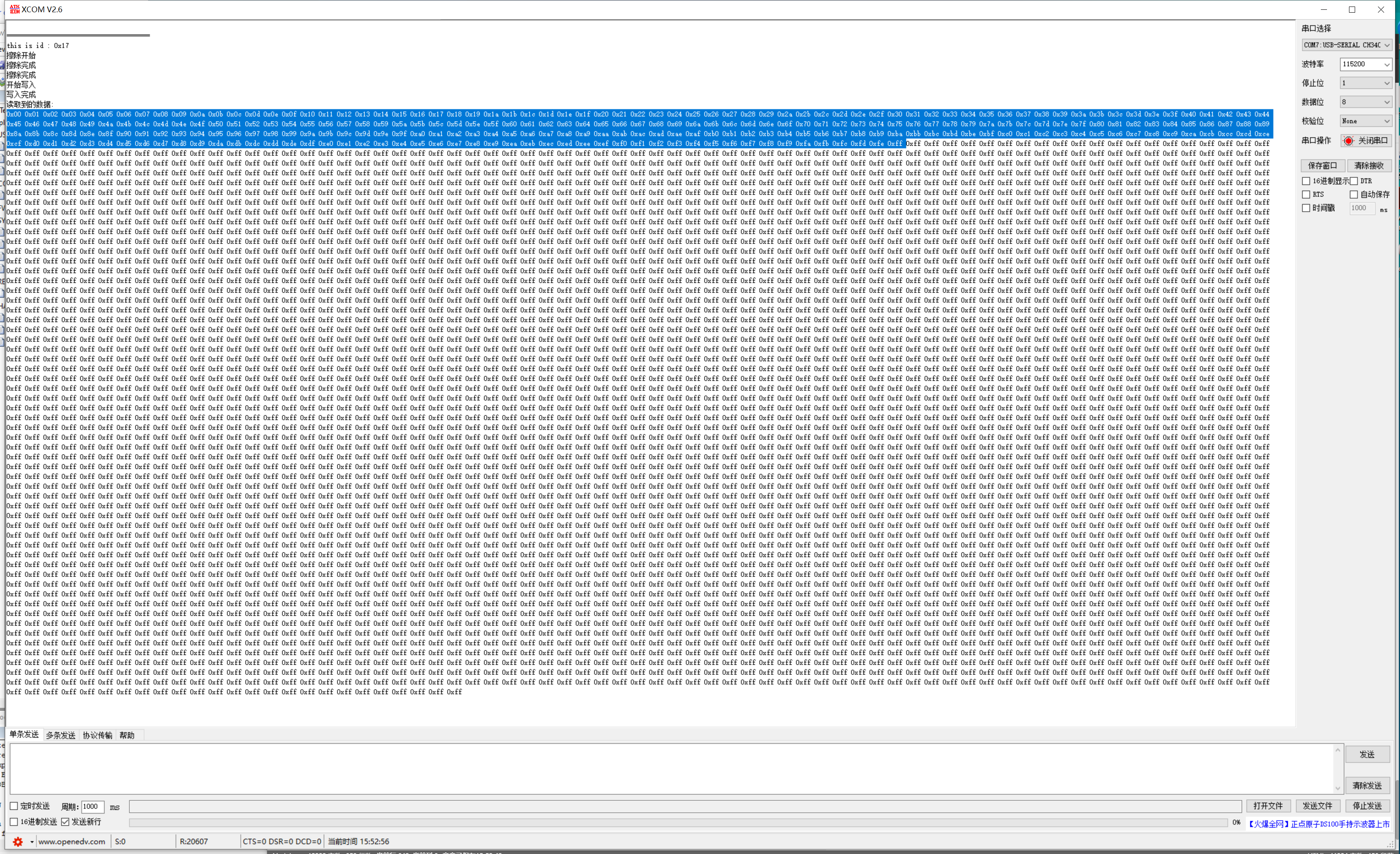
We can see that the first 256 data have been written as the data we want to write, and the rest are 0xFF after erasure.
- Write data to the entire sector.
Modify some parameters of the main function.
	//Initialize data to write
	for(i=0;i<4096;i++)
	{
		write_buff[i] = i;
	}

	printf("\r\n Start writing");

	SPI_FLASH_Write_Buff(0,write_buff,4096);

	printf("\r\n Write complete");

	SPI_FLASH_Read_Buff(0,write_buff,4096);

	printf("\r\n Read data:\r\n");

	for(i=0;i<4096;i++)
	{
		printf("0x%02x ",write_buff[i]);
	}
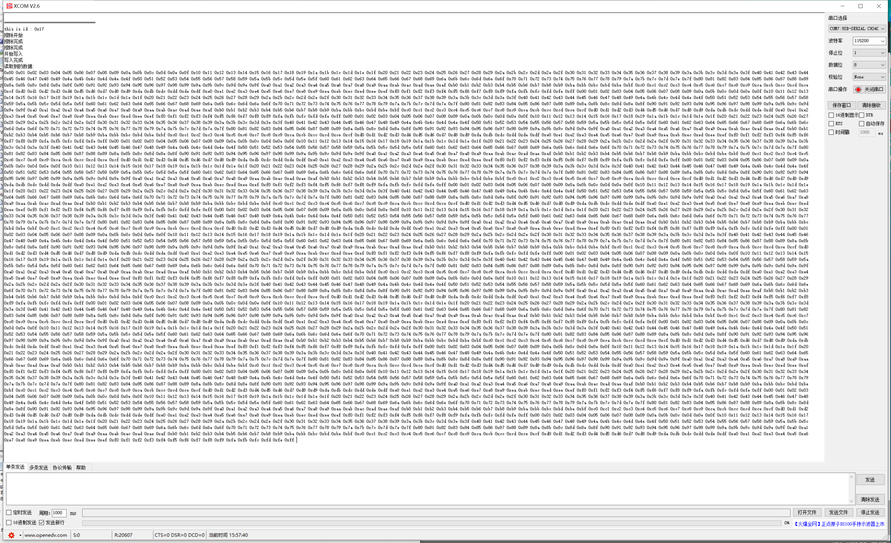
It can be seen that the data of the whole sector is written.