1. Game controller
FC game handle, almost all 9-pin (there is also a 11 pin), the handle also has a feature that can be directly inserted with the serial port head of DR9! In this way, the connection with the development board is simple. The appearance of FC handle is as shown in the figure: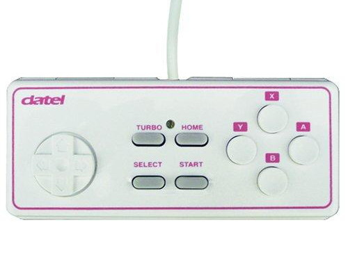
FC handle has 10 buttons (actually only 8):
Up, down, left, right, Start, Select, A, B, A continuous, B continuous.
A and a are key values, while B and B are also key values. However, when you press the button continuously, it will send continuously (convenient and fast keys, such as projectile and other functions).
The control circuit of FC handle is composed of an 8-bit shift register (CD4021) and A time base integrated circuit (NE555) for continuous transmission. The information to read the key value of the handle is very simple: first, pull (lock key value), then get the first key value (A, falling edge acquisition), and then read the key value of other keys successively under the function of 7 clocks, A total of 8 key values. However, in order to save cost, the current handle is bound directly on the PCB. So when you open the handle, you can't see that there is A square IC in it, but there is only A small black dot. All the circuits are integrated into it, but their control and reading methods are the same The reading sequence and wiring diagram of 9-pin handle are shown as follows: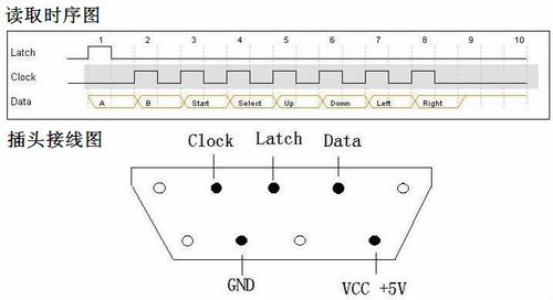
2. Circuit connection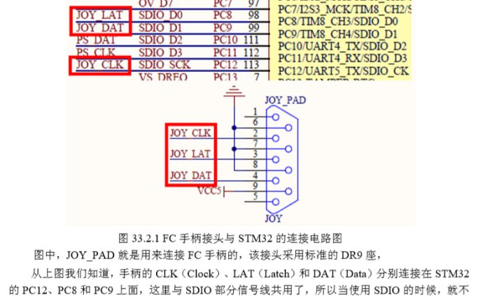
3, procedure
//Handle connection pin
#define JOYPAD_CLK PCout(12)  	//Clock PC9
#define JOYPAD_LAT PCout(8)  	//Locking PC8
#define JOYPAD_DAT PCin(9)	 	//Data PC12
const u8*JOYPAD_SYMBOL_TBL[8]=
{"Right","Left","Down","Up","Start","Select","A","B"};//Handle symbol definition
//Initialize handle interface
void JOYPAD_Init(void)
{
 	RCC->APB2ENR|=1<<4;//Enable PORTC clock
	GPIOC->CRH&=0XFFF0FF00;
	GPIOC->CRH|=0X00030083;
	GPIOC->ODR|=3<<8;
	GPIOC->ODR|=1<<12;
}

//Read handle key value
//FC handle data output format:
//For each given pulse, output one bit of data in the following order:
//A->B->SELECT->START->UP->DOWN->LEFT->RIGHT.
//8 digits in total. For the handle with C, C is A+B pressed at the same time
//Press 0, release 1
//Return value:
//[0]: right.
//[1]: left
//[2]: under
//[3]: on.
//[4]:Start
//[5]:Select
//[6]:B
//[7]:A
u8 JOYPAD_Read(void)
{
	u8 temp=0;
	u8 t,i;
	JOYPAD_LAT=1;					//Lock current state
 	JOYPAD_LAT=0;
	for(t=0;t<8;t++)
	{
		temp<<=1;
		if(JOYPAD_DAT)temp|=0x01;	//Get the first data after LOAD
		JOYPAD_CLK=1;			   	//Every time a pulse is given, a data is received
 		JOYPAD_CLK=0;
	}
	if(temp!=0XFF)//Indicates data received
	{
		LCD_ShowNum(116,130,temp,3,16);//Display key values
		for(i=0;i<8;i++)
		{
			if((temp&(1<<i))==0)//Judge the key value by pressing the position once. If a bit is 0, it means that the corresponding key is pressed
			{
				LCD_Fill(60+56,150,60+56+48,150+16,WHITE);//Clear previous display
				LCD_ShowString(60+56,150,200,16,16,(u8*)JOYPAD_SYMBOL_TBL[i]);//display symbols
			}
		}
	}
}