1. Hardware
The hardware schematic diagram is as follows: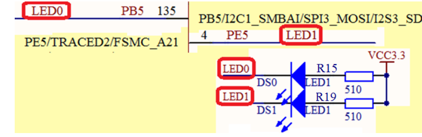
The hardware schematic diagram is the hardware circuit of punctual atom stm32zet6 elite version. Different development boards should be based on the actual circuit. First of all, to make the led light up, there must be a voltage difference between the two sides of the led lamp. As can be seen from the figure, the right side of the lamp is pulled up, and 3.3V is the high level, so our single chip microcomputer can light up only after outputting the low level. Because there is a voltage difference and it is a diode, and there is current flowing through, the analysis shows that the output mode is push output.
2. Software
2.1crl & CRH register
These two registers are port configuration registers. Their function is to configure the output mode of io port, which io port and output speed, that is, GPIO_Mode,GPIO_Pin,GPIO_Speed.
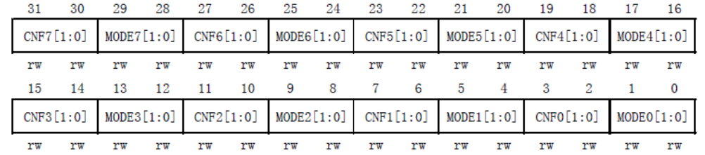
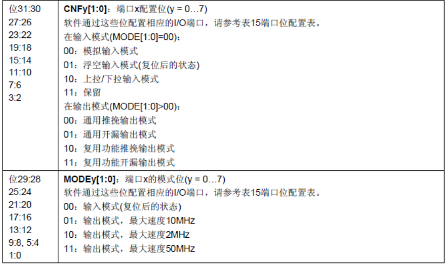
The first four bits configure the status of an io port For example, if PA1 is set to push-pull output and the speed is 50MHz, the first four bits of the CRL register will be 11 00 (from high to high).
2.2IDR register
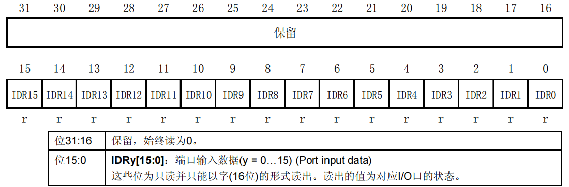
This register is a read-only register. Only the lower 16 bits are used to read the level state of the corresponding io port through this register.
Operate the IDR register in the firmware library to read the level status of the io port. Generally, GPIO is used_ Readinputdatabit() function implementation. For example, read gpioa 5. Our method is GPIO_ReadInputDataBit(GPIOA, GPIO_Pin_5).
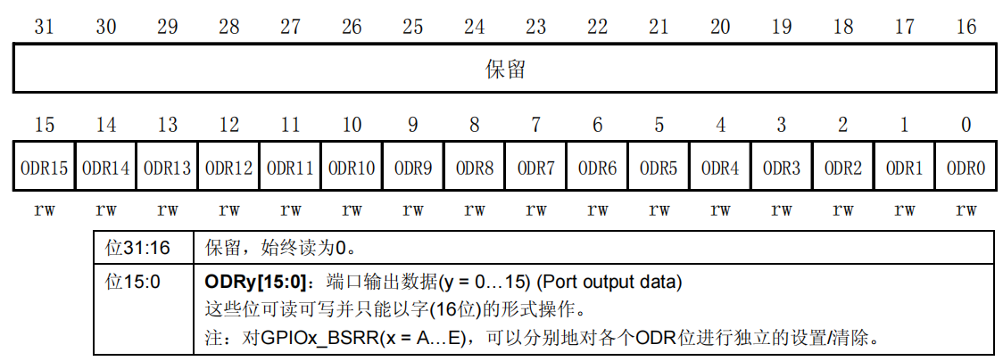
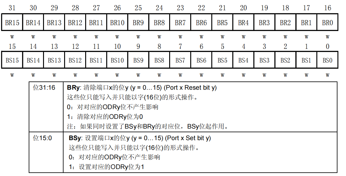
2.3 ord & bsrr register,
1. There are some differences between the two registers, but the two registers set the level accordingly.
2. The ord register can only be read out in the form of words, and then write and modify it. Therefore, this register generally sets the values of multiple ports of GPIO. Using GPIO_ The write() function is implemented.
3.BSRR register and ODR register have similar functions. They can set whether the output bit of the port is 1 or 0, but this register generally sets the value of a single port.
4. Generally, we use void GPIO_SetBits(GPIO_TypeDef* GPIOx, uint16_t GPIO_Pin); void GPIO_ResetBits(GPIO_TypeDef* GPIOx, uint16_t GPIO_Pin) are two functions to set the status of corresponding bits. For example, we set gpioa 5-bit output high level, GPIO method_ SetBits(GPIOA, GPIO_Pin_5); If it is output low level, it is GPIO_ResetBits (GPIOB, GPIO_Pin_5).
3. Experimental code
3.1 peripheral C document code
#include "led.h"
#include "sys.h"


void Init_Led()
{
	GPIO_InitTypeDef GPIO_InitStructure;

	RCC_APB2PeriphClockCmd(RCC_APB2Periph_GPIOB|RCC_APB2Periph_GPIOE,ENABLE);//Enable the clock io port of Series B and E


	/*
		First, configure the CRL|CRH register (each series has the same register) with a total of 32 bits. CRL configuration 1-8 and CRH configuration 9-16
						CRL The first four are PA1, and the latter is similar to PA2. The input and output mode and speed are mainly configured (there are three speeds for output, and there is no speed selection for input)

	*/
	GPIO_InitStructure.GPIO_Mode=GPIO_Mode_Out_PP; //The current required for push-pull output is push-pull output
	GPIO_InitStructure.GPIO_Pin=GPIO_Pin_5;				//PB5 output
	GPIO_InitStructure.GPIO_Speed=GPIO_Speed_50MHz;//Output speed
	GPIO_Init(GPIOB,&GPIO_InitStructure);					//After the initialization mode of the function is set, we will set the function to the corresponding mode
	GPIO_SetBits(GPIOE,GPIO_Pin_5);

	GPIO_InitStructure.GPIO_Mode=GPIO_Mode_Out_PP; //Push-pull output requires current as push-pull output
	GPIO_InitStructure.GPIO_Pin=GPIO_Pin_5;				//PB5 output
	GPIO_InitStructure.GPIO_Speed=GPIO_Speed_50MHz;//Output speed
	GPIO_Init(GPIOB,&GPIO_InitStructure);					//Store the set mode into the function for initialization, and the function will adjust the corresponding register to the way we set it
	GPIO_SetBits(GPIOB,GPIO_Pin_5);
	/*
	IDR Register, which is a read-only register used to read the io status of the current port
	The function to be used is GPIO_ReadInputDataBit(GPIOA, GPIO_Pin_5);
	*/

	/*
	ODR Register this register is the output data register, which is used to read and write the level state of the corresponding port, using only the lower 16 bits

	BSRR Both the upper 16 bits and the lower 16 bits of the register are used to set the high and low levels

	Generally, we use these two functions to set the status of io port GPIO_SetBits(GPIOB, GPIO_Pin_5); Set to 1 high level
																	GPIO_ResetBits (GPIOB, GPIO_Pin_5);Set to 0 		  Low level

	*/


}
3.2 peripheral h file code
#ifndef __LED_H
#define __LED_H
#include "sys.h"

//LED port definition


#define LED0 PBout(5)// DS0
#define LED1 PEout(5)// DS1


void Init_Led(void);//initialization

#endif
3.3main function code
#include "stm32f10x.h"
#include "led.h"
#include "delay.h"

 int main(void)
 {
	 delay_init();
	 Init_Led();

	 while(1)
	 {
		 LED0=0;
		 LED1=1;
		 delay_ms(300);

		 LED0=1;
		 LED1=0;
		 delay_ms(300);
	 }

 }