STM32 review notes (II) -- GPIO lit LED
| MDK version: | MDK 5.35.0.0 |
|---|---|
| Chip model: | STM32F103C8T6 |
| Firmware library version: | STM32F10x_StdPeriph_Lib_V3.5.0 |
1.GPIO port bit mode
Input floating input pull-up input pull-down analog input
Open drain output push-pull output push-pull multiplexing function open drain multiplexing function
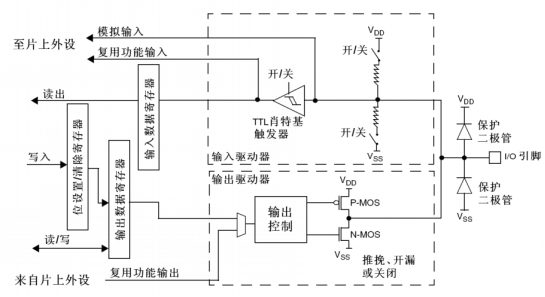
2.GPIO port bit structure (STM32F10xxx refer to figure 13 basic structure of I / O port bit in the manual)
3.GPIO port register
| Two 32-bit configuration registers | GPIOx_CRL and GPIOx_CRH |
|---|---|
| Two 32-bit data registers | GPIOx_IDR and GPIOx_ODR |
| A 32-bit / reset register | GPIOx_BSRR |
| A 16 bit reset register | GPIOx_BRR |
| A 32-bit lock register | GPIOx_LCKR |
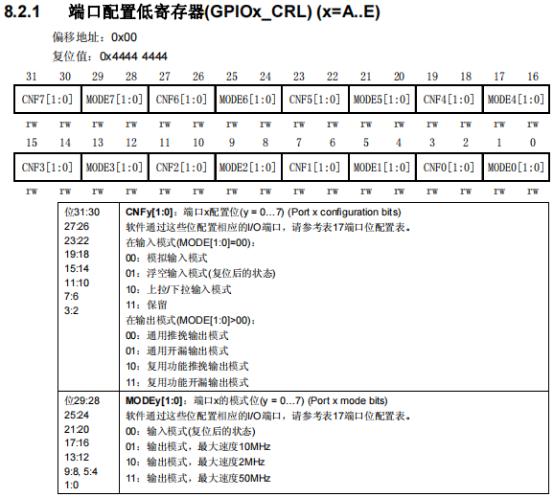
GPIOx_ In CRL register
Every two bit MODEx[1:0] determines the mode (input mode or output mode and rate) of an IO port
Every two bits CNFx[1:0] determines the configuration of an IO port (e.g. general push-pull output mode)
To change the 0 th bit in GPIOA, i.e. GPIO_Pin_0 is configured as push-pull output mode, the output rate is 10MHz, and gpiox can be set_ In the CRL register, MODE0[1:0] is set to 01 and CNF0[1:0] is set to 00. In order not to interfere with the configuration of other bits, use & and | to operate the register, first clear the bits to be set to 0, and then configure them to the required mode
GPIOA->CRL &= ~((uint32_t)0x03); //Clear MODE0[1:0] to 0
GPIOA->CRL |=  ((uint32_t)0x01); //Configure MODE0[1:0] to 01
GPIOA->CRL &= ~((uint32_t)0x03); //Clear CNF0[1:0] 0
GPIOA->CRL |=  ((uint32_t)0x00); //Configure CNF0[1:0] to 00
GPIOx_CRH register usage and cpiox_ Same as CRL
GPIOx_ The CRL register is used to configure the 0 - 7 bits of the gpiox port
GPIOx_ The CRH register is used to configure 8 - 15 bits of the gpiox port
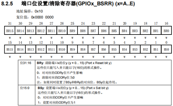
GPIOx_ In bsrr register
The lower 16 bits are used to set the setting of each bit of GPIOx
The upper 16 bits are used to set the reset of each bit of GPIOx
To add GPIO to GPIOA_ Pin_ 0 is set to high level, gpiox can be_ BS0 in the bsrr register is set to 1
GPIOA->BSRR |= (uint32_t)0x01; // Set BS0 to 1
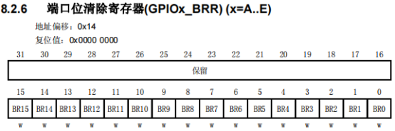
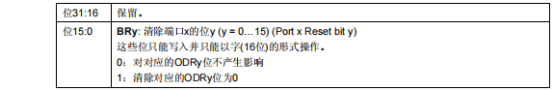
GPIOx_ In BRR register
The lower 16 bits are used to set the reset of each bit of GPIOx
High 16 bit reserved
To add GPIO to GPIOA_ Pin_ 0 is set to low level, gpiox can be_ BR0 in the BRR register is set to 1
GPIOA->BRR |= (uint16_t)0x01; // Set BR0 to 1
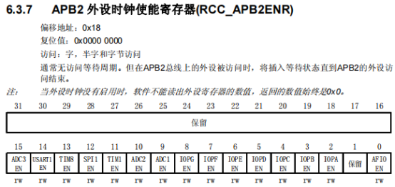
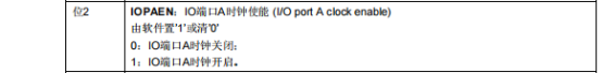
4. Turn on the corresponding clock before using GPIOx peripherals
GPIOx uses APB2 bus and RCC must be configured_ Apb2enr register enable clock
To turn on the GPIOA clock, send it to RCC_ IOPAEN in the apb2enr register is set to 1
RCC->APB2ENR |= ((uint32_t)1<<2); // Set IOPAEN to 1
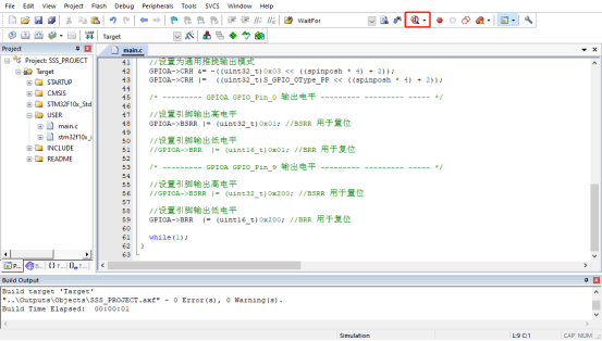
5. Write code
Write code in main.c
#include "stm32f10x.h"
typedef enum
{
S_GPIO_Mode_OUT = 0x01, //Output, rate 10MHz
S_GPIO_OType_PP = 0x00 //Universal push-pull output
}GPIOA_Config_TypeDef;
int main(void)
{
/* GPIO in gpioa_ Pin_ 0 and GPIO_ Pin_ 9 as an example, make its output high level or low level */
//It is used to determine which IO port it is. The value range is 0x00 - 0x07. There are 8 ports in total
uint32_t spinposl = 0x00; //0x00 here indicates GPIO of GPIOA_ Pin_ 0 bit
//It is used to determine which IO port it is. The value range is 0x08 - 0x0F, 8 in total
uint32_t spinposh = 0x01; //0x01 here indicates GPIO of GPIOA_ Pin_ 9 bits
//Turn on the GPIOA clock, and GPIO uses APB2 bus
RCC->APB2ENR |= ((uint32_t)1<<2);
/* CRL Control IO port 0 - 7 bits; CRH control IO port 8 - 15 bits */
/* --------- GPIOA GPIO_Pin_0 Configuration ------------------------- */
//Set the output mode at 10MHz
GPIOA->CRL &= ~((uint32_t)0x03 << (spinposl * 4));
GPIOA->CRL |= ((uint32_t)S_GPIO_Mode_OUT << (spinposl * 4));
//Set to universal push-pull output mode
GPIOA->CRL &= ~((uint32_t)0x03 << ((spinposl * 4) + 2));
GPIOA->CRL |= ((uint32_t)S_GPIO_OType_PP << ((spinposl * 4) + 2));
/* --------- GPIOA GPIO_Pin_9 Configuration ------------------------- */
//Set the output mode at 10MHz
GPIOA->CRH &= ~((uint32_t)0x03 << (spinposh * 4));
GPIOA->CRH |= ((uint32_t)S_GPIO_Mode_OUT << (spinposh * 4));
//Set to universal push-pull output mode
GPIOA->CRH &= ~((uint32_t)0x03 << ((spinposh * 4) + 2));
GPIOA->CRH |= ((uint32_t)S_GPIO_OType_PP << ((spinposh * 4) + 2));
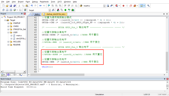
/* --------- GPIOA GPIO_Pin_0 Output level ------------------------------ */
//Set pin output high level
GPIOA->BSRR |= (uint32_t)0x01; //BSRR is used for setting
//Set pin output low level
//GPIOA->BRR |= (uint16_t)0x01; // BRR for reset
/* --------- GPIOA GPIO_Pin_9 Output level ------------------------------ */
//Set pin output high level
//GPIOA->BSRR |= (uint32_t)0x200; // Bsrr is used for setting
//Set pin output low level
GPIOA->BRR |= (uint16_t)0x200; //BRR for reset
while(1);
}
6. Compilation and simulation
Click build
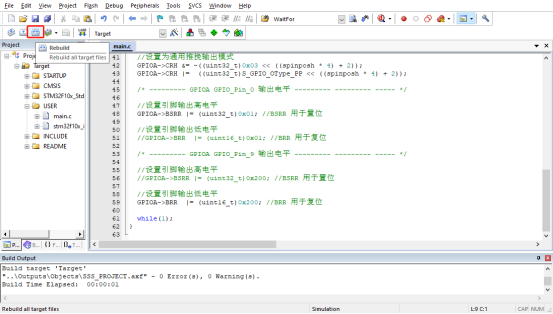
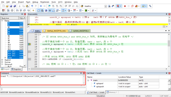
If there is no error in compilation, enter the software simulation (Start/Stop Debug Session, click to enter / exit the simulation)
In case of prompt error
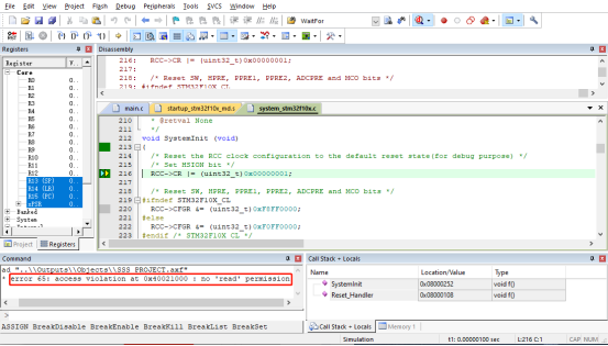
Exit the simulation and open Options for Target... - Debug
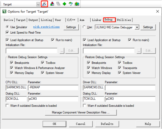
Make the following modifications (note that it is modified to the corresponding chip model)
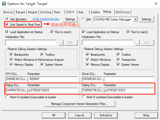
Recompile and enter the software simulation again
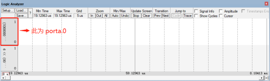
Use logic analyzer to view GPIO of GPIOA_ Pin_ 0 and GPIO_ Pin_ 9 output level
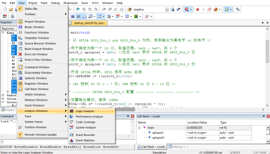
Configure the IO port to view
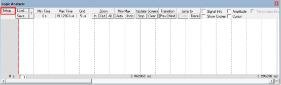
Click the top right corner to add an IO port, as shown in
GPIO of GPIOA_ Pin_ 0 can enter porta.0
GPIO of GPIOA_ Pin_ 9 you can enter porta.9
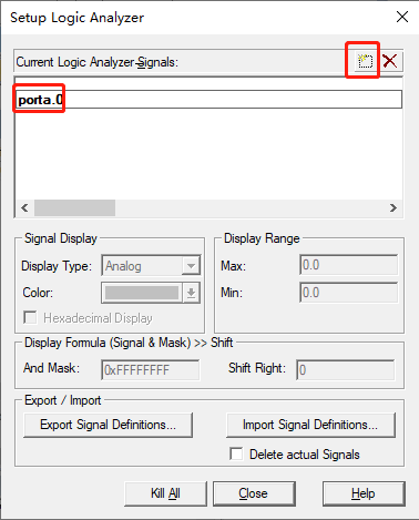
Select Display Type as Bit

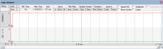
After setting, GPIO can be seen in the logic analyzer_ Pin_ 0 and GPIO_ Pin_ 9 two IO ports
Click Run to view the GPIO in the logic analyzer_ Pin_ 0 and GPIO_ Pin_ 9 output level
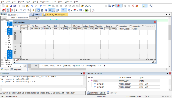
Both IO ports output high level
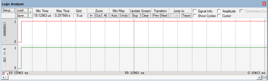
Stop and exit the simulation, GPIO_Pin_9 to output low level

After recompiling, enter the simulation and run again to check the level status of IO port (at this time, GPIO_Pin_9 output is low level)
The template of this project can be copied for subsequent learning of other functions, and can be modified on this basis