1, There are 8 steps about how to configure serial port transceiver through interrupt
1. Enable serial port clock and enable GPIO clock
2. Pin multiplexing mapping
3.GPIO port mode setting
4. Serial port parameter initialization setting
5. Enable interrupt initialization NVIC
6. Enable serial port
7. Write interrupt processing function
8. Write transceiver data processing function
2, Initialize serial port function
1. Enable serial port clock and enable GPIO clock
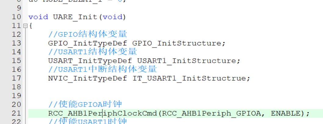
    //Enable GPIOA
	RCC_AHB1PeriphClockCmd(RCC_AHB1Periph_GPIOA, ENABLE);
	//Enable serial port 1
	RCC_APB2PeriphClockCmd(RCC_APB2Periph_USART1, ENABLE);
2. Pin multiplexing mapping
    //GPIOA_Pin_9 mapping serial port 1
	GPIO_PinAFConfig(GPIOA, GPIO_PinSource9, GPIO_AF_USART1);
	//GPIOA_Pin_10 mapping serial port 2
	GPIO_PinAFConfig(GPIOA, GPIO_PinSource10, GPIO_AF_USART1);
3.GPIO port mode setting
    GPIO_InitStructure.GPIO_Mode = GPIO_Mode_AF;     //multiplexing
	GPIO_InitStructure.GPIO_OType = GPIO_OType_PP;   //push-pull
	GPIO_InitStructure.GPIO_Pin = GPIO_Pin_9 | GPIO_Pin_10;;
	GPIO_InitStructure.GPIO_PuPd = GPIO_PuPd_UP;     //Pull up
	GPIO_InitStructure.GPIO_Speed = GPIO_Speed_100MHz;
	//GPIOA initialization ¯
	GPIO_Init(GPIOA, &GPIO_InitStructure);
The structure variables in GPIO initialization need to be defined at the top, including the structure variables of serial port 1 and the structure variables interrupted by serial port 1

4. Serial port parameter initialization setting
    USART1_InitStructure.USART_BaudRate = 115200;                  //Baud rate
    //No hardware stream settings
	USART1_InitStructure.USART_HardwareFlowControl = USART_HardwareFlowControl_None;
	USART1_InitStructure.USART_Mode = USART_Mode_Rx | USART_Mode_Tx; //Input \ output
	USART1_InitStructure.USART_Parity = USART_Parity_No;             //No parity bit
	USART1_InitStructure.USART_StopBits = USART_StopBits_1;          //Set the stop bit to 1
	USART1_InitStructure.USART_WordLength = USART_WordLength_8b;     //Word length 8 bits
	//USART1 initialization
	USART_Init(USART1, &USART1_InitStructure);

    //Enable serial port 1
	USART_Cmd(USART1, ENABLE);
5. Enable interrupt initialization NVIC
	IT_USART1_InitStructrue.NVIC_IRQChannel = USART1_IRQn;      //Interrupt serial port 1 channel
	IT_USART1_InitStructrue.NVIC_IRQChannelCmd = ENABLE;        //Enable interrupt serial port 1 channel
	IT_USART1_InitStructrue.NVIC_IRQChannelPreemptionPriority = 1;  //Preemption priority is 1
	IT_USART1_InitStructrue.NVIC_IRQChannelSubPriority = 1;         //Response priority is 1

	//Serial port interrupt initialization
	NVIC_Init(&IT_USART1_InitStructrue);
6. Enable serial port
    //Enable serial port 1 interrupt service function
	USART_ITConfig(USART1, USART_IT_RXNE, ENABLE);
That's all for configuring the initialization function of interrupt serial port 1.
3, Writing interrupt handling functions
1. Write the corresponding interrupt processing function first. Here, serial port 1 is used, so the corresponding is interrupt service function 1
void USART1_IRQHandler(void)
{

	//If there is data trigger interrupt 1
	if(USART_GetITStatus(USART1, USART_IT_RXNE) != RESET)
	{
		//Clear interrupt flag bit
		USART_ClearITPendingBit(USART1,USART_IT_RXNE);
		//Read out the data received by the serial port interrupt and assign it as Res
		Res =USART_ReceiveData(USART1);
		USART_SendData(USART1, Res);
		switch(USARTReceIn)
		{
			case 0:
				if(Res)   //If Res receives data, it passes the data into the array USARTReceBuff
					USARTReceBuff[USARTReceIn++] = Res;
				else      //Otherwise, USARTReceIn is cleared and re judged
					USARTReceIn = 0;
				break;
			default:
				//If Res receives data, it passes the data into the array USARTReceBuff
				USARTReceBuff[USARTReceIn++] = Res;
				break;
		}
		//If the number of incoming data received is greater than or equal to 8 times, it means that a frame of data is received, and the interrupt flag is placed at one position
		if(USARTReceIn >= 8)
		{
			USARTReceFullFlag = 1;
		}
     }
}
2. Write transceiver data processing function
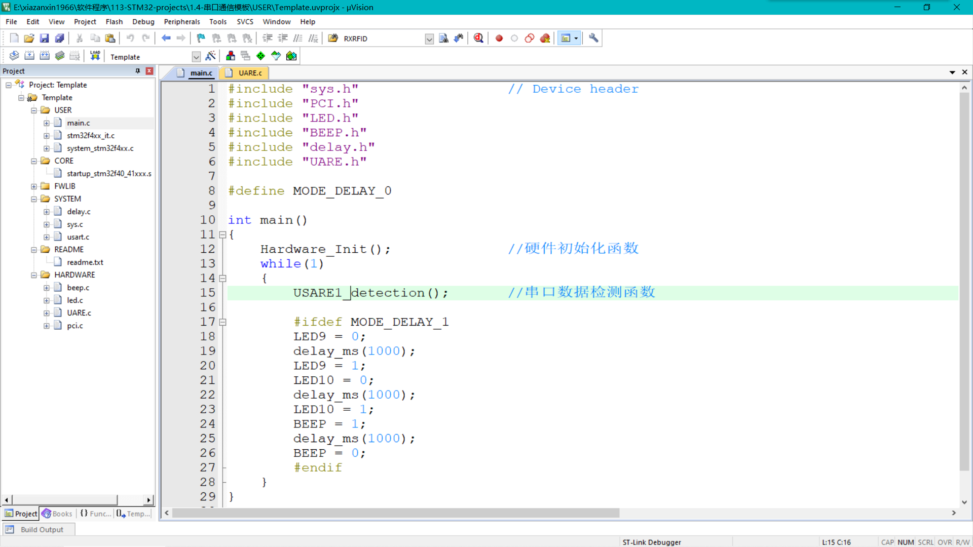
The detection function here is to judge a frame of data. When the serial port receives a frame of 8-bit data, it will be stored in the array, and this detection function is to judge the data and then make the required action
eg: when the serial port receives the data flag position 1, it means that the serial port has received a frame of 8-bit data, then turn on the serial port data flag bit, and then judge whether the first bit of data in the array is 0x88. These can be customized, and some judgment conditions in packet header, packet tail and checksum can be added, So as to judge whether the received data is the data you need. If not, clear the flag bit, do not make any action, and continue to wait for the data of the next frame for judgment
/***************************************************************
 * Function: serial port 1 data detection function USARE1_detection
 * Parameter: None
 * Return value: None
 *
****************************************************************/

void USARE1_detection(void)
{

	if(USARTReceFullFlag)
	{
		if((USARTReceBuff[0] == 0x88))
		{
			GPIO_ResetBits(GPIOF, GPIO_Pin_10);
			GPIO_ResetBits(GPIOF, GPIO_Pin_9);
			GPIO_SetBits(GPIOF, GPIO_Pin_10 | GPIO_Pin_8);
		}else if((USARTReceBuff[0] == 0x99))
		{
			GPIO_ResetBits(GPIOF, GPIO_Pin_10 | GPIO_Pin_8);
			GPIO_SetBits(GPIOF, GPIO_Pin_9);
		}
		USARTReceFullFlag = 0;      //Close serial port data flag bit
		USARTReceIn = 0;            //Serial port received data variable reset
	}
}
okay!!!
A simple serial port receiving function is configured
