1. Brief introduction to LCD12864 display principle
1.1 brief introduction to liquid crystal principle
In fact, the LCD screen is composed of pixels, and there are several pixels in each row and column. The data bit width (or pixel depth) occupied by each pixel is different for different types of screens. For example, for A true color screen, each pixel occupies 24bit or 32bit data, that is, RGB888 or ARGB8888 (where A represents transparency); For the gray-scale screen (yes, that kind of black-and-white TV), one pixel generally occupies only 8bit; The black-and-white screen with only black and white colors can be represented by 1 bit data bit. Generally speaking, the more data bits it occupies, the richer the colors it can represent, and the more it can truly present the original colors in nature. The screen pixels are shown in the figure below:
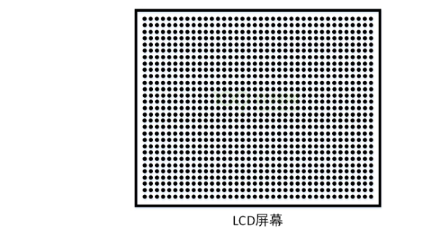
For LCD12864 display, there are 128 * 64 pixels. If we want to display characters, characters or even pictures on the screen, we can display the corresponding words, characters or pictures as long as we light the corresponding pixels according to a certain law, and the data that lights the pixels according to a certain law is called lattice data (the lattice data of pictures is generally called bitmap).
Expansion: in fact, for lattice data and bitmap data of pictures, the data processing of this part is relatively complex, such as data matrix conversion, inverse selection of lattice data, etc. In addition, for the bitmap data of a picture, the amount of data is very huge. Here is an example: for a picture with a resolution of 1920x1080 and a pixel depth of 24bit true color, its size is 1920 x 1080 x 24bit = 5.93MB, that is to say, the size of a picture can solve the amount of 6MB data. What if it's video data? The amount of data can be amazing. But the pictures or videos we come into contact with in our life are actually compressed. Here we use extremely complex compression algorithms. When we want to present the pictures or videos to us, we must decompress them according to the law of compression, which involves decompression algorithms. In short, the processing of these data will actually involve a lot of knowledge. Interested partners can find relevant materials and learn by themselves.
Let's use A group of 8x16 character A lattice data to explain how this group of data can display 'A' on the screen. Character A dot matrix data is shown in the figure below:
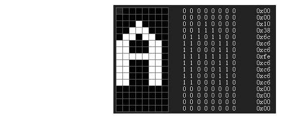
Among them, 1 represents lit pixels and 0 represents not lit. Then, we light the bit with 1 of each byte of data on the 8x16 pixel grid, while the bit with 0 is not lit. In this way, we can present A character 'A' on the screen. However, one question is, how can we write this set of lattice data to the display screen (in fact, write the data to A piece of video memory in the display screen)?
For this, different screens will use different communication protocols. According to the communication protocol requirements specified on the screen, they can write corresponding lattice data to the screen, so as to display the text, icons, pictures and so on they want to display. Because the display screen used by the driver code in this article is LCD12864, the communication timing used by LCD12864 is briefly introduced below.
1.2 LCD12864 interface timing
-
Pins used
Generally, LCD12864 has 20 pins. You can learn from this manual. All pins are shown in the figure below:
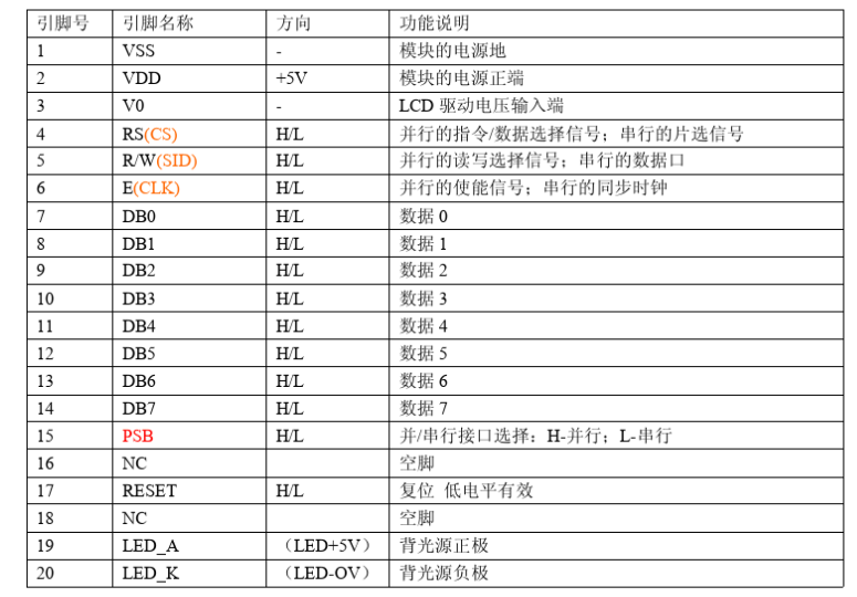
What I use here is the serial communication mode of 12864, so I only use some pins related to serial connection. The pins of LCD12864 and my STM32 board (the model I use is STM32F103VET6) are connected as follows:CLK — PA5
SID — PA6
CS — PA7
PSB — GND
For 12864 power supply and backlight pins, connect the power supply on the board according to your own screen requirements. It should be noted here that the PSB pin is a serial parallel control pin. If the code does not want to control, it can be directly grounded and selected as serial. In addition, if the code of CS chip selection pin does not want to be controlled, it can be directly connected to VCC (3.3V) to keep high level all the time.
-
LCD serial read-write timing
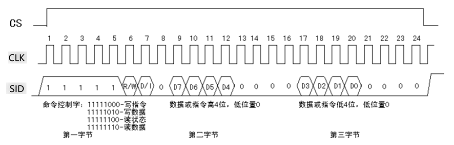
When writing code, this timing chart is very important. According to this timing chart, you can read and write data to LCD12864. As can be seen from the above timing diagram, to send 1 byte of data, in fact, 3 bytes of data need to be sent. First, the read-write command control, then the high 4 bits of the data, and then the low 4 bits of the data. Only in this process can a write process be completed.The address, location and command meaning of other data buffers of LCD12864 are not introduced here. In fact, these can be found in the manual. We'd better go directly to the code and learn about them from the comments of the code.
2. Code implementation
2.1 pin configuration and delay function
2.1.1 pin configuration used by LCD12864
/**
  * @brief  LCD12864 Pin configuration used
  * @param  nothing
  * @retval nothing
  */
void lcd_gpio_config(void)
{
	GPIO_InitTypeDef  GPIO_InitStructure;

	/* Turn on GPIOA clock */
	RCC_APB2PeriphClockCmd(RCC_APB2Periph_GPIOA, ENABLE);

	/* PA7(CS), PA5(CLK), PA6(SID)Pin configuration */
	GPIO_InitStructure.GPIO_Pin = LCD_CS_GPIO_PIN | LCD_CLK_GPIO_PIN | LCD_SID_GPIO_PIN;
	GPIO_InitStructure.GPIO_Mode = GPIO_Mode_Out_PP;
	GPIO_InitStructure.GPIO_Speed = GPIO_Speed_50MHz;
	GPIO_Init(GPIOA, &GPIO_InitStructure);

	/* Control pin initial state all output low level */
	LCD_CS(0);
	LCD_CLK(0);
	LCD_SID(0);
}
2.1.2 delay function used
The delay function is only a simple delay, not very accurate. But I've also been tested. I've compared the stopwatch and can basically match it.
/**
  * @brief  us Delay function, stm32f1 series, 72MHz frequency, compared with the stopwatch, with little error
  * @param  us: us Delay Time
  * @retval nothing
  */
void delay_us(unsigned int us)
{
	unsigned short i = 0;
	while(us--)
	{
		i = 8;
		while(i--);
	}
}

/**
  * @brief  ms Delay function, stm32f1 series, 72MHz frequency, compared with the stopwatch, with little error
  * @param  ms: ms Delay Time
  * @retval nothing
  */
void delay_ms(unsigned int ms)
{
	unsigned short i = 0;
	while(ms--)
	{
		i = 8100;
		while(i--);
	}
}
2.2 LCD12864 driver related codes
2.2.1 serial transmission of one byte of data
/**
  * @brief  LCD12864 Send one byte of data serially
  * @param  byte: One byte data
  * @retval nothing
  */
static void lcd_send_byte(unsigned char byte)
{
	unsigned char i;

	for(i=0; i<8; i++)
	{
		LCD_CLK(0);
		LCD_SID(byte & (0x80 >> i));   	// Send by bit
		delay_us(5);
		LCD_CLK(1);
	}
}
2.2.2 write command
The process of LCD12864 writing commands or data is actually the sequence diagram of serial reading and writing above. The sequence diagram is described in detail below. To send one byte of data, you actually need to send three bytes of data. The first byte number is to tell 12864 whether I want to send commands or data. The next two bytes are to split the commands / data I send into high-4 bits and low-4 bits for transmission (this is specified in the timing diagram. 12864 of different specifications may have different timing, which should be noted here).
/**
  * @brief  LCD12864 Write command
  * @param  cmd: Command to send
  * @retval nothing
  */
static void lcd_write_cmd(unsigned char cmd)
{
	LCD_CS(1);
	delay_ms(1);
	lcd_send_byte(0xf8);   		// Write command
	lcd_send_byte(0xf0 & cmd); 	// Write high 4-bit instruction
	lcd_send_byte(cmd << 4);   	// Write low 4-bit instruction
	LCD_CS(0);
}
2.2.3 write data
/**
  * @brief  LCD12864 Write data
  * @param  data: Data to send
  * @retval nothing
  */
static void lcd_write_data(unsigned char data)
{
	LCD_CS(1);
	delay_ms(1);     			// If the delay time is too long, serious screen flashing will occur in the drawing mode. I found that there is basically no flash screen below 100us
	lcd_send_byte(0xfa);   		// Write data
	lcd_send_byte(0xf0 & data); // Write up 4-bit data
	lcd_send_byte(data << 4);   // Write lower 4-bit data
	LCD_CS(0);
}
2.2.4 LCD12864 initialization
LCD12864 initialization. In fact, its specification has an initialization flow chart. You can set 12864 initially according to the flow chart in the manual.
/**
  * @brief  LCD12864 initialization
  * @param  nothing
  * @retval nothing
  */
void lcd_init(void)
{
	delay_ms(50);   			// Power on self-test delay
	lcd_write_cmd(0x30);       	// Select basic instruction set, 8bit data stream
	delay_ms(1);
	lcd_write_cmd(0x0c);        // On display, off cursor
	delay_ms(1);
	lcd_write_cmd(0x01);        // Clear display
	delay_ms(30);
}
2.3 LCD12864 display string function
Here, the LCD12864 function for displaying strings uses the built-in font library of 12864 (including Chinese font library), rather than the lattice data font defined by itself. The internal font is actually the address of DDRAM, and the pixels occupied by each address value are 16x16 pixels. The English characters with the font are 8x16 pixels and the Chinese characters are 16x16 pixels. Therefore, 12864 can display 16 English characters and 8 Chinese characters in each line, a total of 4 lines.
/* LCD12864 The DDRAM address displayed by the internal font library, each address accounts for 16 * 16 pixels */
static unsigned char lcd_str_addr[4][8] = {
	{0x80, 0x81, 0x82, 0x83, 0x84, 0x85, 0x86, 0x87},
	{0x90, 0x91, 0x92, 0x93, 0x94, 0x95, 0x96, 0x97},
	{0x88, 0x89, 0x8A, 0x8B, 0x8C, 0x8D, 0x8E, 0x8F},
	{0x98, 0x99, 0x9A, 0x9B, 0x9C, 0x9D, 0x9E, 0x9F}
};

/**
  * @brief  LCD12864 display string
  * @param  column: Row address 0 ~ 3, row: column address 0 ~ 7
  * @retval nothing
  */
void lcd_draw_str(unsigned char column, unsigned char row, const char *str)
{
	/* Set the row / column address displayed */
	lcd_write_cmd(lcd_str_addr[column][row]);

	/* Write character by character */
	while(*str)
    {
      lcd_write_data(*str++);
    }
}
2.4 LCD drawing function code
LCD12864 also provides a storage space for drawing and display. By writing different data, we can display different contents we want in this space, such as drawing points, lines, pictures, etc. To write data to this storage space, we first have to switch 12864 to extended instruction mode. Without much to say, let's go straight to the code.
2.4.1 setting coordinate function
Firstly, the coordinates we set are in the unit of LCD12864 dot matrix pixels. A pixel is the coordinates of a certain position. The LCD12864 display screen in my hand is divided into upper and lower half screens for this drawing space. The starting address of the x-axis of the upper half screen is 0x80 and the starting address of the x-axis of the lower half screen is 0x88. In addition, for the x-axis, each additional address actually occupies 16 pixels, while for the y-axis, each additional address occupies only one pixel. The code is as follows:
/**
  * @brief  Set LCD12864 display coordinates
  * @param  x: x Axis coordinates 0~127, y: y axis coordinates 0 ~ 63
  * @retval nothing
  */
static void lcd_setXY(unsigned char x, unsigned char y)
{
	if (y >= 32)
	{
		/* Lower half screen */
		lcd_write_cmd(0x80 + (y - 32));	// y coordinate
		lcd_write_cmd(0x88 + (x>>4));	// x coordinate
	}
	else
	{
		/* Upper half screen */
		lcd_write_cmd(0x80 + y);
		lcd_write_cmd(0x80 + (x>>4));
	}
}
When the y coordinate is greater than or equal to 32, it is in the lower half of the screen, because the addresses of the upper and lower half of the screen are different, and the classification settings are different. In addition, the x-axis coordinate is increased by x > > 4. This is because one address of the x-axis occupies 16 pixels, so it needs to move 4 to the right, which is actually divided by 8.
2.4.2 clear screen function
Clearing the screen is actually sending 0x00 data to the drawing space. The purpose of clearing the screen can be achieved by turning off all pixels.
/**
  * @brief  Clear screen
  * @param  nothing
  * @retval nothing
  */
void lcd_clear(void)
{
	unsigned char x, y;

	lcd_write_cmd(0x34);    // Switch to extended instruction set

	for(y=0; y<64; y++)
	{
		lcd_setXY(0, y);	// Set display coordinates
  		for(x=0; x<8; x++)
  		{
			/* Because one address of the x-axis corresponds to 16 pixels, two bytes of data can be sent continuously */
  		    lcd_write_data(0x00);
			lcd_write_data(0x00);
  		}
	}

    lcd_write_cmd(0x36);    // Open plot display
	lcd_write_cmd(0x30);    // Back to basic instruction set
}
This function actually cycles 8 times on the x-axis and writes 16 bytes of data at a time. Therefore, every time an address is added on the x-axis, 16 pixels are moved (we must pay attention to this, otherwise it is difficult to understand), so it only needs to cycle 8 times. For the y-axis, every time the address is added, it only moves to the next pixel, so it needs to cycle 64 times.
2.4.3 drawing function
In fact, the principle of the drawing function is similar to that of the function of clearing the screen, except that the drawing function writes the picture lattice data to the drawing storage space (but it must be noted that the lattice data of the picture used conforms to the pixel scanning mode of the display screen. As mentioned above, an address on the x axis corresponds to 16 pixels and an address on the y axis corresponds to one pixel). The code is as follows:
/**
  * @brief  Display the picture. Note that the starting point coordinates are fixed (0, 0)
  * @param  nothing
  * @retval nothing
  */
void lcd_draw_picture(const unsigned char *data)
{
	unsigned char x, y;

	lcd_write_cmd(0x34);    // Switch to extended instruction set

	for(y=0; y<64; y++)
	{
		lcd_setXY(0, y);	// Set display coordinates
  		for(x=0; x<8; x++)
  		{
  		    lcd_write_data(*data++);
			lcd_write_data(*data++);
  		}
	}

    lcd_write_cmd(0x36);    // Open plot display
	lcd_write_cmd(0x30);    // Back to basic instruction set
}
2.4.4 draw any point
Drawing any point in the drawing area requires a little skill. The reason is that one address of the x-axis corresponds to 16 pixels. We need to make one pixel of the 16 pixels light up and the other pixels turn off according to the x-axis coordinate points in the data of 16 bytes sent at a time. The code is as follows:
/* x Bit code table displayed by bit of axis */
static const unsigned char set_pix_bit[8] = {0x80, 0x40, 0x20, 0x10, 0x08, 0x04, 0x02, 0x01};

/* Display buffer */
static unsigned char disp_buff[8][64] = {0};

/**
  * @brief  Draw any point within the LCD display range
			x The coordinate range is 0 ~ 127, and the y coordinate range is 0 ~ 63
  * @param  x: x Axis coordinates, y: y axis coordinates, color: color value, 1: lit pixel, 0: not lit
  * @retval nothing
  */
void lcd_draw_dots(unsigned char x, unsigned char y, unsigned char color)
{
	lcd_write_cmd(0x34);       // Switch to extended instruction set

	/* Out of display range, exit function */
	if ((x >= 128) || (y >= 64))
        return;

	/* Set x, y coordinates */
	lcd_setXY(x, y);

	/* Fill display buffer data */
	if (color == 1)
	{
		/* Light up a pixel */
		disp_buff[x>>3][y] |= 0x00;
		disp_buff[(x>>3)+1][y] |= set_pix_bit[x & 0x07];
	}
	else
	{
		/* Turn off a pixel */
		disp_buff[x>>3][y] |= 0x00;
		disp_buff[(x>>3)+1][y] &= ~set_pix_bit[x & 0x07];
	}

	/* Output data to LCD display */
	if ((x >> 3) % 2 != 0)	// Judge the parity of 0 ~ 15 display data on the x-axis
	{
		/* Odd number */
		lcd_write_data(disp_buff[x>>3][y]);
		lcd_write_data(disp_buff[(x>>3)+1][y]);
	}
	else
	{
		/* even numbers */
		lcd_write_data(disp_buff[(x>>3)+1][y]);
		lcd_write_data(disp_buff[x>>3][y]);
	}

    lcd_write_cmd(0x36);        // Open plot display
	lcd_write_cmd(0x30);        // Back to basic instruction set
}
2.4.5 draw horizontal lines
After the function of drawing any point is written, the function of drawing lines is much easier. The code is as follows:
/**
  * @brief  Draw a horizontal line
  * @param  x0: x Axis start point, y0: y0 axis start point, x1: x axis end point, color: color value, 1 lit pixel, 0 not lit
  * @retval nothing
  */
void lcd_draw_Hline(unsigned char x0, unsigned char y0, unsigned char x1, unsigned char color)
{
	/* Out of display range, exit function */
	if ((x0 >= 128) || (y0 >= 64) || (x1 >= 128))
        return;

	for ( ; x1>=x0; x0++)
		lcd_draw_dots(x0, y0, color);
}
2.4.6 draw vertical lines
/**
  * @brief  Draw vertical lines
  * @param  x0: x Axis start point, y0: y axis start point, y1: y axis end point, color: color value, 1 illuminates pixels, 0 does not illuminate
  * @retval nothing
  */
void lcd_draw_Vline(unsigned char x0, unsigned char y0, unsigned char y1, unsigned char color)
{
	/* Out of display range, exit function */
	if ((x0 >= 128) || (y0 >= 64) || (y1 >= 64))
        return;

	for ( ; y1>=y0; y0++)
		lcd_draw_dots(x0, y0, color);
}
The above is the functions of LCD12864 functions I implemented. I have tested these codes. I found no bug s in my own test. They can normally display strings, pictures, draw arbitrary points, draw lines, etc. However, I found that when drawing pictures or lines in the drawing mode, if the delay time is too long when sending data / commands, there will be serious screen flashing. When the delay time is adjusted to less than 100us, there will be basically no screen flashing.
If a small partner finds a bug in the process of reproducing the code, you are welcome to point it out. If you can't get the results of the experiment, you can also discuss it with me.