Configuration flow for serial port sending process
Serial register definition file in HAL library:
stm32f429xx.h F429 chip
stm32f767xx.h F767 chip
stm32f103xx.h F103 chip
stm32fnnnx.x.h Other Chips
USART_can be found in it TypeDef: Eventually maps to the address of the register.
typedef struct
{
  __IO uint32_t CR1;    /*!< USART Control register 1,                 Address offset: 0x00 */
  __IO uint32_t CR2;    /*!< USART Control register 2,                 Address offset: 0x04 */
  __IO uint32_t CR3;    /*!< USART Control register 3,                 Address offset: 0x08 */
  __IO uint32_t BRR;    /*!< USART Baud rate register,                 Address offset: 0x0C */
  __IO uint32_t GTPR;   /*!< USART Guard time and prescaler register,  Address offset: 0x10 */
  __IO uint32_t RTOR;   /*!< USART Receiver Time Out register,         Address offset: 0x14 */
  __IO uint32_t RQR;    /*!< USART Request register,                   Address offset: 0x18 */
  __IO uint32_t ISR;    /*!< USART Interrupt and status register,      Address offset: 0x1C */
  __IO uint32_t ICR;    /*!< USART Interrupt flag Clear register,      Address offset: 0x20 */
  __IO uint32_t RDR;    /*!< USART Receive Data register,              Address offset: 0x24 */
  __IO uint32_t TDR;    /*!< USART Transmit Data register,             Address offset: 0x28 */
} USART_TypeDef;
Serial function definition file in HAL library:
stm32f7xx_hal_uart.c ,stm32f7xx_hal_usart.c
Serial Byte Sending Process:
- Programming USARTx_ The M bit of CR1 defines the word length.
- Programming USARTx_ The STOP bit of CR2 defines the stop bit.
- Programming USARTx_ The BRR register determines the baud rate.
- Enable USARTx_ The UE bit of CR1 enables USARTx.
- Configure USARTx_for multi-buffer communication DMA Enabling (DMAT) for CR3. Refer to the later DMA experiment specifically.
- Enable USARTx_ The TE bit of CR1 enables the transmitter.
- Writes the data to be sent to the send data register TDR (for M3, send and receive shared DR registers).
- After writing the last data to the TRD register, wait for the status register USARTx_ TC position 1 of SR (ISR), transmission complete.
For stm32f4: Control Register 1 (USART_CR1):
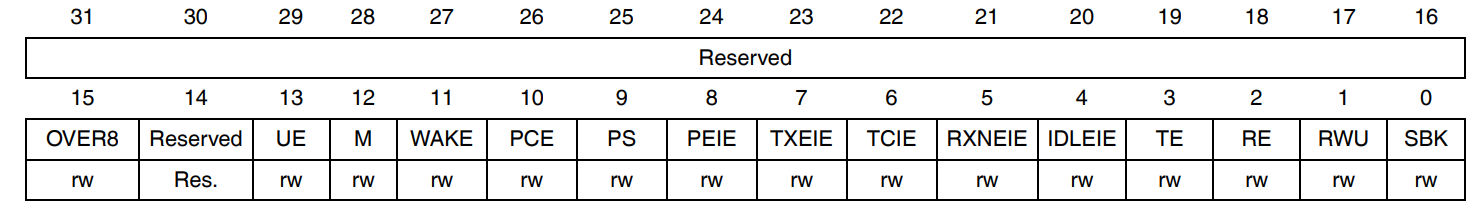
Bit 12M: Word length This bit determines the word length. This bit is set to 1 or zero by the software.
0:1 start bit, 8 data bits, n stop bit
1:1 Start Bit, 9 Data Bit, n Stop Bit
Note: M-bit must not be changed during data transmission (send and receive)
stm32f4 control register 2 (USART_CR2):
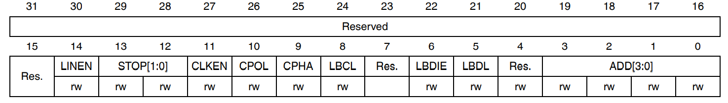
Bit 13:12 STOP: STOP bit
These bits are used for programming stop bits.
00:1 stop bit
01:0.5 stop bits
10:2 stop bits
11:1.5 stop bits
Note: 0.5 stop bits and 1.5 stop bits are not suitable for UART4 and UART5.
1, 2, 3 in the serial byte sending process set some parameters of the serial port. Next, to use the serial port:
Also found in stm32f4 control register 1 (USART_CR1):
Bit 13 UE:USART enable
When this bit is cleared, the USART prescaler and output will stop and end the current byte transfer to reduce power consumption. This bit is set 1 and cleared by the software.
0: Disable USART Predividers and Outputs
1: Enable USART
Bit 3 TE: Transmitter enable
This bit enables the transmitter. This bit is set 1 and cleared by the software.
0: Prohibit transmitters
1: Enable transmitter
Note: 1: Except in smart card mode, a "0" pulse ("0" followed by "1") on the TE bit during transmission sends a header (idle line) after the current word.
2: When TE is set to 1, there is a 1-bit time delay before sending starts.
After the 4, 5, 6 steps in the serial port byte sending process are enabled, the next step is data sending, that is, 7, 8 steps.
Serial Byte Sending Flow (HAL Library Function)
Configuration steps 1~_: Configure word length, stop bits, parity bits, baud rate, etc.
Can be in stm32f7xx_ Hal_ Uart. Found in c: HAL_StatusTypeDef HAL_UART_Init(UART_HandleTypeDef *huart) function: The identifier u is referenced inside the function HAL_USART_ENABLE enables the corresponding serial port.
/**
  * @brief Initializes the UART mode according to the specified
  *         parameters in the UART_InitTypeDef and creates the associated handle .
  * @param huart: uart handle
  * @retval HAL status
  */
HAL_StatusTypeDef HAL_UART_Init(UART_HandleTypeDef *huart)
{
  /* Check the UART handle allocation */
  if(huart == NULL)
  {
    return HAL_ERROR;
  }

  if(huart->Init.HwFlowCtl != UART_HWCONTROL_NONE)
  {
    /* Check the parameters */
    assert_param(IS_UART_HWFLOW_INSTANCE(huart->Instance));
  }
  else
  {
    /* Check the parameters */
    assert_param(IS_UART_INSTANCE(huart->Instance));
  }

  if(huart->gState == HAL_UART_STATE_RESET)
  {
    /* Allocate lock resource and initialize it */
    huart->Lock = HAL_UNLOCKED;

    /* Init the low level hardware : GPIO, CLOCK */
    HAL_UART_MspInit(huart);
  }

  huart->gState = HAL_UART_STATE_BUSY;

  /* Disable the Peripheral */
  __HAL_UART_DISABLE(huart);

  /* Set the UART Communication parameters */
  if (UART_SetConfig(huart) == HAL_ERROR)
  {
    return HAL_ERROR;
  }

  if (huart->AdvancedInit.AdvFeatureInit != UART_ADVFEATURE_NO_INIT)
  {
    UART_AdvFeatureConfig(huart);
  }

  /* In asynchronous mode, the following bits must be kept cleared:
  - LINEN and CLKEN bits in the USART_CR2 register,
  - SCEN, HDSEL and IREN  bits in the USART_CR3 register.*/
  CLEAR_BIT(huart->Instance->CR2, (USART_CR2_LINEN | USART_CR2_CLKEN));
  CLEAR_BIT(huart->Instance->CR3, (USART_CR3_SCEN | USART_CR3_HDSEL | USART_CR3_IREN));

  /* Enable the Peripheral */
  __HAL_UART_ENABLE(huart);

  /* TEACK and/or REACK to check before moving huart->gState and huart->RxState to Ready */
  return (UART_CheckIdleState(huart));
}
Steps_~_Send data and wait for sending to complete: can be in stm32f7xx_ Hal_ Uart. Found in c: HAL_UART_Transmit function:
HAL_StatusTypeDef HAL_UART_Transmit(UART_HandleTypeDef *huart, uint8_t *pData, uint16_t Size, uint32_t Timeout)
_u weak keyword:
Prefix function with u The weak modifier, which we call a weak function. For weak functions, the user can redefine a function with the same name in the user file, and the final compiler will compile with the user-defined function selected. If the user has no definition, then the function content is the content of the weak function definition.
Function declaration:
Can be in stm32f7xx_ Hal_ Uart. Found in h: void HAL_UART_MspInit(UART_HandleTypeDef *huart);
Function Definition (Weak Function): Nothing to do inside
__weak void HAL_UART_MspInit(UART_HandleTypeDef *huart)
{
}
Weak functions are called by other functions:
HAL_StatusTypeDef HAL_UART_Init(UART_HandleTypeDef *huart)
{
if(huart->gState == HAL_UART_STATE_RESET)
{
/* Allocate lock resource and initialize it */
huart->Lock = HAL_UNLOCKED;
/* Init the low level hardware : GPIO, CLOCK */
HAL_UART_MspInit(huart);
}
}
Why define a weak function?
Since there are other functions in the hal library that need to call such a function, but the contents are not sure how to initialize it, first define a weak function. Then the user can write the real content of the function again. In this case, no function redefinition error will be reported. Running a process is the same, but initialization may be different. The advantage of using the weak function is that we don't make any modifications to the existing process, just modify some user-related code in the process.
Weak function redefined:
void HAL_UART_MspInit(UART_HandleTypeDef *huart)
{
...//Content
}
_u Benefits of the weak keyword:
- For a pre-defined process, we only want to modify some user-related code in the process, at which point we can use a weak function to define an empty function, and then let the user define the function. The advantage of this is that we will not make any modifications to the existing process.
- Heavy use of u in HAL Libraries The weak keyword modifies the peripheral callback function.
- The peripheral callback function allows users to write MCU-related programs, which greatly improves the universality and portability of programs.
Serial Sender Configuration Procedure (HAL Library):
- Initialize serial port related parameters to enable serial port:HAL_UART_Init();
- Serial port related IO port configuration, multiplexing configuration: in HAL_ UART_ Calling HAL_in MspInit GPIO_ Init function.
- Send data and wait for it to finish: HAL_UART_Transmit() function;
Then start writing code based on the above process:
Initialize serial port related parameter HAL_UART_Init();
First compile an initialization function:
void uart1_init(void)
{

}
Then in HALLIB-stm32f7xx_ Hal_ Uart. Found in c: HAL_UART_Init function, paste it into the initialization function, call it:
He then finds that he has an entry parameter, UART_HandleTypeDef *huart is the structure pointer part. Then find UART_ Definition of HandleTypeDef, you can find: This is a serial handle
typedef struct
{
  USART_TypeDef            *Instance;        /*!< UART registers base address        */

  UART_InitTypeDef         Init;             /*!< UART communication parameters      */

  UART_AdvFeatureInitTypeDef AdvancedInit;   /*!< UART Advanced Features initialization parameters */

  uint8_t                  *pTxBuffPtr;      /*!< Pointer to UART Tx transfer Buffer */

  uint16_t                 TxXferSize;       /*!< UART Tx Transfer size              */

  uint16_t                 TxXferCount;      /*!< UART Tx Transfer Counter           */

  uint8_t                  *pRxBuffPtr;      /*!< Pointer to UART Rx transfer Buffer */

  uint16_t                 RxXferSize;       /*!< UART Rx Transfer size              */

  uint16_t                 RxXferCount;      /*!< UART Rx Transfer Counter           */

  uint16_t                 Mask;             /*!< UART Rx RDR register mask          */

  DMA_HandleTypeDef        *hdmatx;          /*!< UART Tx DMA Handle parameters      */

  DMA_HandleTypeDef        *hdmarx;          /*!< UART Rx DMA Handle parameters      */

  HAL_LockTypeDef           Lock;            /*!< Locking object                     */

  __IO HAL_UART_StateTypeDef    gState;      /*!< UART state information related to global Handle management
                                                  and also related to Tx operations.
                                                  This parameter can be a value of @ref HAL_UART_StateTypeDef */

  __IO HAL_UART_StateTypeDef    RxState;     /*!< UART state information related to Rx operations.
                                                  This parameter can be a value of @ref HAL_UART_StateTypeDef */

  __IO uint32_t             ErrorCode;   /*!< UART Error code                    */

}UART_HandleTypeDef;
USART_TypeDef is the type of serial port. In the file you can find:
#define USART2              ((USART_TypeDef *) USART2_BASE)
#define USART3              ((USART_TypeDef *) USART3_BASE)
#define UART4               ((USART_TypeDef *) UART4_BASE)
#define UART5               ((USART_TypeDef *) UART5_BASE)
Then find UART_ As you can see from the definition of InitTypeDef, there are some feature parameters that configure the serial peripheral.
typedef struct
{
  uint32_t BaudRate;                  /*!< This member configures the UART communication baud rate.
                                           The baud rate register is computed using the following formula:
                                           - If oversampling is 16 or in LIN mode,
                                              Baud Rate Register = ((PCLKx) / ((huart->Init.BaudRate)))
                                           - If oversampling is 8,
                                              Baud Rate Register[15:4] = ((2 * PCLKx) / ((huart->Init.BaudRate)))[15:4]
                                              Baud Rate Register[3] =  0
                                              Baud Rate Register[2:0] =  (((2 * PCLKx) / ((huart->Init.BaudRate)))[3:0]) >> 1      */

  uint32_t WordLength;                /*!< Specifies the number of data bits transmitted or received in a frame.
                                           This parameter can be a value of @ref UARTEx_Word_Length */

  uint32_t StopBits;                  /*!< Specifies the number of stop bits transmitted.
                                           This parameter can be a value of @ref UART_Stop_Bits */

  uint32_t Parity;                    /*!< Specifies the parity mode.
                                           This parameter can be a value of @ref UART_Parity
                                           @note When parity is enabled, the computed parity is inserted
                                                 at the MSB position of the transmitted data (9th bit when
                                                 the word length is set to 9 data bits; 8th bit when the
                                                 word length is set to 8 data bits). */

  uint32_t Mode;                      /*!< Specifies whether the Receive or Transmit mode is enabled or disabled.
                                           This parameter can be a value of @ref UART_Mode */

  uint32_t HwFlowCtl;                 /*!< Specifies whether the hardware flow control mode is enabled
                                           or disabled.
                                           This parameter can be a value of @ref UART_Hardware_Flow_Control */

  uint32_t OverSampling;              /*!< Specifies whether the Over sampling 8 is enabled or disabled, to achieve higher speed (up to fPCLK/8).
                                           This parameter can be a value of @ref UART_Over_Sampling */

  uint32_t OneBitSampling;            /*!< Specifies whether a single sample or three samples' majority vote is selected.
                                           Selecting the single sample method increases the receiver tolerance to clock
                                           deviations. This parameter can be a value of @ref UART_OneBit_Sampling */
}UART_InitTypeDef;
You can write in the initialization function:
UART_HandleTypeDef usart1_handler;

void uart1_init(void)
{
	usart1_handler.Instance = USART1;
	usart1_handler.Init.BaudRate = 115200;
	usart1_handler.Init.WordLength = UART_WORDLENGTH_8B;
	usart1_handler.Init.StopBits = UART_STOPBITS_1;
	usart1_handler.Init.HwFlowCtl = UART_HWCONTROL_NONE;
	usart1_handler.Init.Mode = UART_MODE_TX_RX;
	usart1_handler.Init.Parity = UART_PARITY_NONE;
	HAL_UART_Init(&usart1_handler);
}
What are the parameters here? You can start at HALLIB-stm32f7xx_hal_uart.c Find assert_ Param (IS_UART_INSTANCE (huart->Instance)); Then double-click IS_ UART_ INSTANCE finds its definition and finds the following code: then you know what parameters you can fill in, and you can choose USART1 as the parameter. Other parameter settings are similar.
#define IS_UART_INSTANCE(__INSTANCE__) (((__INSTANCE__) == USART1) || \
                                    ((__INSTANCE__) == USART2) || \
                                    ((__INSTANCE__) == USART3) || \
                                    ((__INSTANCE__) == UART4)  || \
                                    ((__INSTANCE__) == UART5)  || \
                                    ((__INSTANCE__) == USART6) || \
                                    ((__INSTANCE__) == UART7)  || \
                                    ((__INSTANCE__) == UART8))
Serial related IO port configuration HAL_UART_MspInit
In HALLIB-stm32f7xx_ Hal_ Uart. HAL_can be found in H UART_ MspInit's declaration: void HAL_UART_MspInit(UART_HandleTypeDef *huart);
Now write this function: eventually it will be HAL_UART_Init call. Since STM32 has several UART serial ports, make a judgment first
void HAL_UART_MspInit(UART_HandleTypeDef *huart)
{
	if(huart->Instance==UART1)
	{

	}
}
Port reuse configuration process:
1.GPIO port clock enabled.
_u HAL_RCC_GPIOA_CLK_ENABLE(); // Enable GPIO clock
2. Multiplex peripheral clock enabling.
For example, if you want to reuse port PA9 and PA10 as a serial port, you need to be able to use the serial clock.
_u HAL_RCC_USART1_CLK_ENABLE(); // Enable serial port 1 clock
3. Port mode is configured for reuse. HAL_GPIO_Init function.
GPIO_Initure.Mode=GPIO_MODE_AF_PP; // Multiplex push-pull output
4. Configure GPIOx_AFRL or GPIOx_AFRH register that connects IO to the desired AFx. HAL_GPIO_Init function.
GPIO_Initure.Alternate=GPIO_AF7_USART1; // Reuse to USART1
For ports, GPIO_needs to be set InitTypeDef *GPIO_ Init parameter. as follows
typedef struct
{
  uint32_t Pin;       /*!< Specifies the GPIO pins to be configured.
                           This parameter can be any value of @ref GPIO_pins_define */

  uint32_t Mode;      /*!< Specifies the operating mode for the selected pins.
                           This parameter can be a value of @ref GPIO_mode_define */

  uint32_t Pull;      /*!< Specifies the Pull-up or Pull-Down activation for the selected pins.
                           This parameter can be a value of @ref GPIO_pull_define */

  uint32_t Speed;     /*!< Specifies the speed for the selected pins.
                           This parameter can be a value of @ref GPIO_speed_define */

  uint32_t Alternate;  /*!< Peripheral to be connected to the selected pins.
                            This parameter can be a value of @ref GPIO_Alternate_function_selection */
}GPIO_InitTypeDef;
After all these settings are completed, the following serial IO port configuration codes are available:
void HAL_UART_MspInit(UART_HandleTypeDef *huart)
{
	GPIO_InitTypeDef GPIO_Initure;
	if(huart->Instance==UART1)
	{
		__HAL_RCC_GPIOA_CLK_ENABLE();			//Enable GPIOA clock
		__HAL_RCC_USART1_CLK_ENABLE();			//Enable USART1 clock
		GPIO_Initure.Pin=GPIO_PIN_9;			//PA9
		GPIO_Initure.Mode=GPIO_MODE_AF_PP;		//Multiplex push-pull output
		GPIO_Initure.Pull=GPIO_PULLUP;			//Pull Up
		GPIO_Initure.Speed=GPIO_SPEED_HIGH;		//high speed
		GPIO_Initure.Alternate=GPIO_AF7_USART1;	//Reuse to USART1
		HAL_GPIO_Init(GPIOA,&GPIO_Initure);	   	//Initialize PA9

		GPIO_Initure.Pin=GPIO_PIN_10;			//PA10
		HAL_GPIO_Init(GPIOA,&GPIO_Initure);	   	//Initialize PA10

	}
}
Send Data HAL_UART_Transmit()
First at stm32f7xx_ Hal_ Uart. HAL_found in C StatusTypeDef HAL_ UART_ Transmit (UART_HandleTypeDef *huart, uint8_t *pData, uint16_t Size, uint32_t Timeout)
You can then discover some of the parameters to be invoked here.
Final code:
#include "sys.h"
#include "delay.h"
#include "usart.h"

UART_HandleTypeDef usart1_handler;

void uart1_init(void)
{
	usart1_handler.Instance = USART1;
	usart1_handler.Init.BaudRate = 115200;
	usart1_handler.Init.WordLength = UART_WORDLENGTH_8B;
	usart1_handler.Init.StopBits = UART_STOPBITS_1;
	usart1_handler.Init.HwFlowCtl = UART_HWCONTROL_NONE;
	usart1_handler.Init.Mode = UART_MODE_TX_RX;
	usart1_handler.Init.Parity = UART_PARITY_NONE;
	HAL_UART_Init(&usart1_handler);
}
void HAL_UART_MspInit(UART_HandleTypeDef *huart)
{
	GPIO_InitTypeDef GPIO_Initure;
	if(huart->Instance==USART1)
	{
		__HAL_RCC_GPIOA_CLK_ENABLE();			//Enable GPIOA clock
		__HAL_RCC_USART1_CLK_ENABLE();			//Enable USART1 clock
		GPIO_Initure.Pin=GPIO_PIN_9;			//PA9
		GPIO_Initure.Mode=GPIO_MODE_AF_PP;		//Multiplex push-pull output
		GPIO_Initure.Pull=GPIO_PULLUP;			//Pull Up
		GPIO_Initure.Speed=GPIO_SPEED_HIGH;		//high speed
		GPIO_Initure.Alternate=GPIO_AF7_USART1;	//Reuse to USART1
		HAL_GPIO_Init(GPIOA,&GPIO_Initure);	   	//Initialize PA9

		GPIO_Initure.Pin=GPIO_PIN_10;			//PA10
		HAL_GPIO_Init(GPIOA,&GPIO_Initure);	   	//Initialize PA10

	}
}

int main(void)
{
	u8 buff[]="test";
  Cache_Enable();                 //Open L1-Cache
  HAL_Init();				        //Initialize HAL Library
  Stm32_Clock_Init(432,25,2,9);   //Set clock, 216Mhz
	delay_init(216);
	uart1_init();
	while(1)
	{
		HAL_UART_Transmit(&usart1_handler,buff,sizeof(buff),1000);

		delay_ms(300);

	}

}