Principle of ultrasonic ranging
Using sound ranging, the speed of sound in the air is 340m/s(15 ℃)
When the sound propagates, it will bounce back if it encounters an obstacle. The distance from the transmitting end to the obstacle can be calculated by counting the rebound time
S=v*(t/2)
Ultrasonic module instruction
In the single chip microcomputer, the ranging function is realized with the help of ultrasonic module, and the display feedback is carried out through serial port debugging assistant or display screen
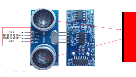
The measurement range of HC-SR04 ultrasonic module is 2cm-400cm, and the accuracy can reach 3mm.
Pin function:
VCC pin: 5V power supply.
TRIG pin: trigger signal pin. The single chip microcomputer sends a signal to the ultrasonic module, and the ultrasonic module will work.
ECHO pin: ECHO signal pin. When the ultrasonic module has successfully measured the distance, it will tell the MCU the current ultrasonic transmission time through this pin.
GND: signal ground.
Working principle of the module:
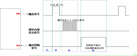
1. At first, both Trig and Echo pins are in the low-level state;
2. Then pull the TRIG pin up for at least 10 microseconds and then down to let the ultrasonic module start working;
3. At this time, the module will automatically send 8 40KHz square waves as the starting signal;
4. When the initial signal is transmitted, the ECHO pin will be pulled high. If a signal returns, the ECHO pin will automatically detect the reflected signal and be pulled low. Then the high-level duration of the ECHO pin is the time from transmission to return.
The measured distance is:
S = (duration of ECHO pin high level * 340m/s) / 2
S=t x 170
Because the timer of single chip microcomputer generally uses us for timing, the formula can be converted into
S= t x 170 x 10-6=t/58 (cm)
Ultrasonic precautions
1. The propagation speed of sound is different at different temperatures. There is the following formula:
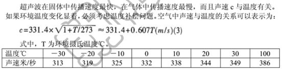
Generally, when the temperature is 15 ℃, v=340m/s, the temperature and humidity sensor can be added to measure the ambient temperature when measuring the distance, which can be brought into the formula to dynamically calculate the sound velocity value to make the measurement more accurate;
2. During ranging, the measured object shall be as flat as possible and the area shall not be less than 0.5 square meters, otherwise the measurement results will be affected;
2. The measurement error of ultrasonic is 3mm. The measurement time can be calculated according to the ranging of 3mm. The calculation is as follows:
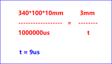
This formula is used here to measure the distance. When the delay is 9us, that is, ECHO continues high level 9us, the measured distance is 3mm, which is only an approximate value here.
HMI serial port screen
The serial port screen used in this experiment comes from taojingchi merchants
Model: TJC3224K024_011R
320x240 resolution
_ 011: hardware version number
K0 series
2.4-inch screen (diagonal distance)
Touch screen Description: N = no touch, R = resistive touch screen, C = capacitive touch screen
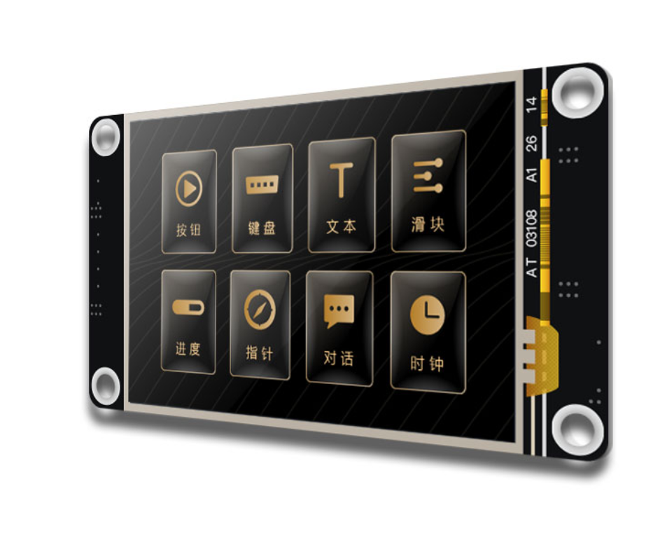
Compared with LCD (liquid crystal screen) and OLED (organic light emitting display), the serial port screen is simpler, with only four wires. It uses serial port communication, and the screen is rich and colorful, which can be displayed on color screen.
LCD:32 pins, using IIC or SPI communication
OLED: limited display colors, up to two colors
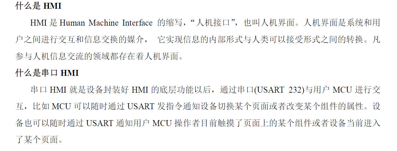
Compared with other businesses, Tao Jingchi's serial port screen is relatively simple to use. You only need to abide by its serial port screen protocol.
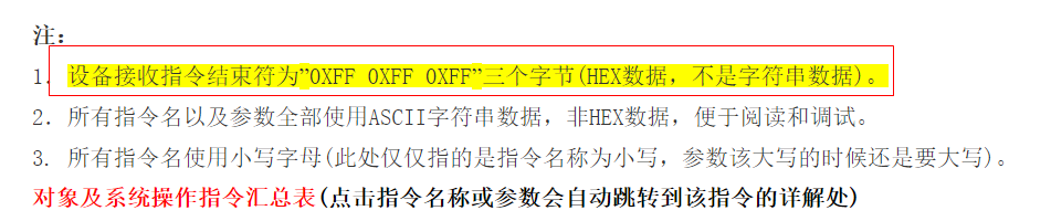
This is its syntax rule. You only need to add three 0xff bytes after the control as the terminator. There are no other rules.
The serial port screen interface designed in this experiment:
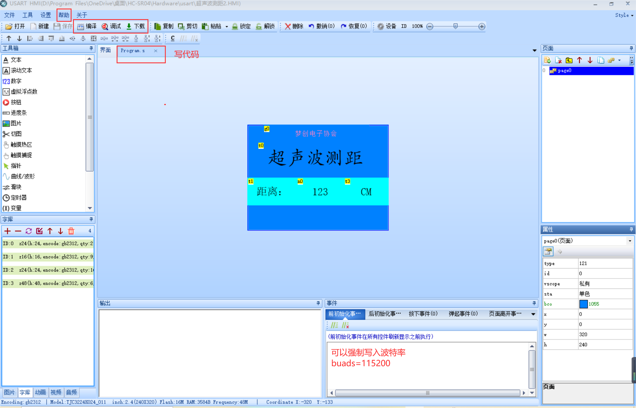
Because this software is in Chinese, we don't introduce it too much. We can directly click the help document to learn. The official website introduces the use of this software in detail, but there is little introduction to the communication with MCU. However, the official document gives a clear description, which belongs to advanced application, but there is no more introduction.
Precautions for HMI serial port screen:
1. When a word library is added to the screen, the word library will have text or digital display. It is best to add the word library in the form of the specified word library. Do not add all the word libraries, otherwise it will be very slow to download to the screen.
2. The serial port screen data transmission supports two ways of downloading: ① serial port number search and download ②; SD memory card download.
3. The format requirements for uploading pictures on the screen are: png pictures. According to the size of the screen, it will limit the size of the pictures. Only smaller pictures can be loaded in.
For the learning of controls, you can directly download USART HMI Software for learning, click the help in the software to learn, or directly log in to Tao Jingchi's official website for learning.
Finally, make some explanations on some error prone places:
1. When the serial port screen is connected with the STM32 development board, pull out the jumper cap of serial port 1, connect PA9 and PA10 to TX and RX pins of serial port screen respectively, and connect serial port 1 of wildfire compass to CH340 chip by default.
After removing the jumper cap, the first step is to cross connect the TX and RX pins of the serial port screen and CH340 chip, download the screen interface designed in the upper computer of USART HMI to the serial port screen, download the program, and then unplug the connections PA9 and PA10 to communicate with the chip.
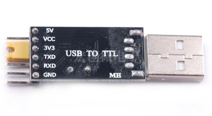
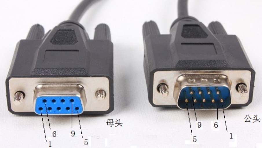
2. The function of CH340 is a bridge. It can convert TTL level to USB level. Generally, the output of single chip microcomputer is TTL level. If you want to communicate between single chip microcomputer and computer, you need USB interface. Previously, DB9 interface was used to communicate with computer, but now it is rarely used. The main reason is that USB is more compact and convenient for communication.
3. The baud rate of the serial port screen must be set to be the same as the baud rate of the written program before communication can be carried out. Although the upper computer can change the screen baud rate, the screen baud rate may have been fixed when leaving the factory. Even if the upper computer is forced to change, the communication cannot be carried out normally. If the baud rate of the screen is not known, the download screen interface can be searched automatically, There will be a display on it.
Although many things have been eliminated, mainly because of the progress of the times and the continuous renewal and iteration of science and technology, the birth of new things comes from old objects. The knowledge involved in old objects will never be eliminated. Unless a kind of knowledge is proved to be wrong, the wrong things will certainly be eliminated, just like we are still learning various laws summarized by Newton for thousands of years, If these laws are proved to be wrong, then we don't need to learn any more. There are too many knowledge to learn today, and there are many ways to learn. To roam in the ocean of knowledge, we must stand on the shoulders of giants.
The serial port debugging assistant can also display data. When the jumper cap is removed, the serial port debugging assistant can not be used, or other serial ports can be used to connect the serial port debugging assistant. Here, the baud rate should be set to the same before communication
Code parsing
hc-sr04.h
The initialization of ultrasonic module is programmed according to the sequence diagram
#ifndef  __HCSR04_H
#define  __HCSR04_H

#include "stm32f10x.h"

//Ultrasonic module pin
#define	TRIG_PORT      GPIOC
#define	ECHO_PORT      GPIOC
#define 	 TRIG_ PIN       GPIO_ Pin_ eight 	// Trig transmit pin PC8
#define 	 ECHO_ PIN       GPIO_ Pin_ nine 		// Echo receive pin PC9

//Ultrasonic module initialization
void sr04_init(void);

//Ultrasonic module ranging
int32_t sr04_get_distance(void);

#endif
hc-sr04.c
#include "hc-sr04.h"
#include "stm32f10x.h"
#include "delay.h"

uint32_t d;      //Calculated distance

//Ultrasonic initialization function
void sr04_init(void)
{
	GPIO_InitTypeDef GPIO_InitStructure;

	RCC_APB2PeriphClockCmd(RCC_APB2Periph_GPIOC, ENABLE);//Clock enable

	GPIO_InitStructure.GPIO_Pin = TRIG_PIN;		//PC8 connected to TRIG
	GPIO_InitStructure.GPIO_Mode = GPIO_Mode_Out_PP;//Push pull output mode
	GPIO_InitStructure.GPIO_Speed = GPIO_Speed_50MHz;	      //speed
	GPIO_Init(TRIG_PORT, &GPIO_InitStructure);	         //Initialize GPIO

	GPIO_InitStructure.GPIO_Pin = ECHO_PIN;				 //PC9 connected to ECH0
	GPIO_InitStructure.GPIO_Mode = GPIO_Mode_IN_FLOATING; //Floating input
	GPIO_Init(ECHO_PORT,&GPIO_InitStructure);		//Initialize GPIO

	GPIO_ResetBits(GPIOC,GPIO_Pin_8);//The initial state of PC8 is low level. See the sequence diagram
}

/*Get distance*/
int32_t sr04_get_distance(void)
{
	uint32_t t;

	//PC8 high level
	GPIO_SetBits(TRIG_PORT,TRIG_PIN);
	delay_us(20);	//Lasting more than 10us
	GPIO_ResetBits(TRIG_PORT,TRIG_PIN);//PC8 low level

	while(!GPIO_ReadInputDataBit(ECHO_PORT,ECHO_PIN));	//Wait for high level

	//Wait for the high level of PC9
	t=0;
	while(ECHO_PIN==0)
	{
		//timeout handler
		t++;
		delay_us(1);

		//If it times out, an error code is returned
		if(t >= 10000)
			return -1;

	}

	//Measure the time of high level
	t=0;
	while(GPIO_ReadInputDataBit(ECHO_PORT,ECHO_PIN))
	{
		t++;
		delay_us(9);	//9us == 3mm

		//If it times out, an error code is returned
		if(t >= 10000)
			return -2;
	}

	//Because the measured time is the time from the emission to the return of the ultrasonic wave
	d = t*0.3;

	return d;

}
delay.h
#ifndef __DELAY_H
#define __DELAY_H

#include "stm32f10x.h"

void delay_us(uint32_t n);
void delay_ms(uint32_t n);

#endif
delay.c
#include "delay.h"

void delay_us(uint32_t n)
{
	SysTick->CTRL = 0; 			// Disable SysTick to turn off the system timer
	SysTick->LOAD = (168*n)-1; // Configuration count value (168*n)-1 ~ 0
	SysTick->VAL  = 0; 		// Clear current value as well as count flag
	SysTick->CTRL = 5; 		// Enable SysTick timer with processor clock
	while ((SysTick->CTRL & 0x10000)==0);// Wait until count flag is set
	SysTick->CTRL = 0; 		// Disable SysTick
}

void delay_ms(uint32_t n)
{
	while(n--)
	{
		SysTick->CTRL = 0; 		// Disable SysTick to turn off the system timer
		SysTick->LOAD = (168000)-1; 	// Configuration count value (168000) - 1 ~ 0
		SysTick->VAL  = 0; // Clear current value as well as count flag
		SysTick->CTRL = 5; 	// Enable SysTick timer with processor clock
		while ((SysTick->CTRL & 0x10000)==0);// Wait until count flag is set
	}

	SysTick->CTRL = 0; 		// Disable SysTick

}
usart.h
#ifndef   __USART_H
#define	  __USART_H

#include "stm32f10x.h"
#include "stdio.h"

/*Serial port 1 Parameter macro definition*/
#define USART1_CLK 			 RCC_APB2Periph_USART1 / / serial port clock
#define USART1_BAUDRATE 		 9600 / / baud rate

//Serial port 1 GPIO pin macro definition
#define USART1_GPIO_CLK		RCC_APB2Periph_GPIOA
#define USART1_GPIO_TX_PORT	GPIOA
#define USART1_GPIO_TX_PIN	GPIO_Pin_9
#define USART1_GPIO_RX_PORT	GPIOA
#define USART1_GPIO_RX_PIN	GPIO_Pin_10

//interrupt
#define  USART1_IRQ                USART1_IRQn
#define  USART1_IRQHandler         USART1_IRQHandler

//Serial port function
void USART1_Config(void);
void Usart_SendByte( USART_TypeDef * pUSARTx, uint8_t data);
void USART_SendString(USART_TypeDef* USARTx, char *DataString);


#endif /* __USART1_H */
usart.c
//Serial port
void USART1_Config(void)
{
	GPIO_InitTypeDef GPIO_InitStructure;
	USART_InitTypeDef USART_InitStructure;
	NVIC_InitTypeDef  NVIC_InitStructure;

	/* config USART1 clock */
	RCC_APB2PeriphClockCmd(RCC_APB2Periph_USART1|RCC_APB2Periph_GPIOA, ENABLE);

	/* USART1 GPIO config */
	/* Configure USART1 Tx (PA.09) as alternate function push-pull */
	GPIO_InitStructure.GPIO_Pin = GPIO_Pin_9;
	GPIO_InitStructure.GPIO_Mode = GPIO_Mode_AF_PP;
	GPIO_InitStructure.GPIO_Speed = GPIO_Speed_50MHz;
	GPIO_Init(GPIOA, &GPIO_InitStructure);
	/* Configure USART1 Rx (PA.10) as input floating */
	GPIO_InitStructure.GPIO_Pin = GPIO_Pin_10;
	GPIO_InitStructure.GPIO_Mode = GPIO_Mode_IN_FLOATING;
	GPIO_Init(GPIOA, &GPIO_InitStructure);

	/* USART1 mode config */
	USART_InitStructure.USART_BaudRate = USART1_BAUDRATE;//Baud rate
	USART_InitStructure.USART_WordLength = USART_WordLength_8b;//8 data bits
	USART_InitStructure.USART_StopBits = USART_StopBits_1;//1 stop bit
	USART_InitStructure.USART_Parity = USART_Parity_No ;//No check
	USART_InitStructure.USART_HardwareFlowControl = USART_HardwareFlowControl_None;//No hardware control flow
	USART_InitStructure.USART_Mode = USART_Mode_Rx | USART_Mode_Tx;
	USART_Init(USART1, &USART_InitStructure);//Serial port initialization completed
	USART_ITConfig(USART1, USART_IT_RXNE, ENABLE);//Enable serial port

	//Configure the interrupt triggering method of serial port 1: receive a byte to trigger the interrupt
	USART_ITConfig(USART1, USART_IT_RXNE, ENABLE);

	//Configure interrupt priority of serial port 1
	NVIC_InitStructure.NVIC_IRQChannel = USART1_IRQn;
	NVIC_InitStructure.NVIC_IRQChannelPreemptionPriority = 0;
	NVIC_InitStructure.NVIC_IRQChannelSubPriority = 0;
	NVIC_InitStructure.NVIC_IRQChannelCmd = ENABLE;
	NVIC_Init(&NVIC_InitStructure);

	USART_Cmd(USART1, ENABLE);
}


/*****************  Send a byte**********************/

void Usart_SendByte(USART_TypeDef * pUSARTx, uint8_t data)
{
	/* Send a byte of data to USART */
	USART_SendData(pUSARTx,data);

	/* The waiting to send data register is empty */
	while (USART_GetFlagStatus(pUSARTx, USART_FLAG_TXE) == RESET);
}

/*****************  Send string**********************/

void USART_SendString(USART_TypeDef* USARTx, char *DataString)
{
	int i = 0;
	USART_ClearFlag(USARTx,USART_FLAG_TC);										//Clear the flag bit before sending the character (otherwise the first character of the string is missing)
	while(DataString[i] != '\0')												//String Terminator
	{
		USART_SendData(USARTx,DataString[i]);									//Send one character of the string at a time
		while(USART_GetFlagStatus(USARTx,USART_FLAG_TC) == 0);					//Wait for data to be sent successfully
		USART_ClearFlag(USARTx,USART_FLAG_TC);									//Clear flag bit after sending characters
		i++;
	}
}

//Redirect the c library function printf to the serial port. After resetting, you can use the printf function
int fputc(int ch, FILE *f)
{
		/* Send a byte of data to the serial port */
		USART_SendData(USART1, (uint8_t) ch);

		/* Wait for sending to complete */
		while (USART_GetFlagStatus(USART1, USART_FLAG_TXE) == RESET);

		return (ch);
}

int fgetc(FILE *f)
{
		/* Wait for serial data input */
		while (USART_GetFlagStatus(USART1, USART_FLAG_RXNE) == RESET);

		return (int)USART_ReceiveData(USART1);
}
stm32f10x_it.c interrupt service function
#include "stm32f10x_it.h"
#include "usart.h"
#include "stdio.h"

void USART1_IRQHandler(void)
{
	u8 d;
	if(USART_GetITStatus(USART1, USART_IT_RXNE) != RESET)
	{
	    d=USART1->DR;
	  	printf("%c",d);    //Return the received data directly to print
	}

}
main.c
/**********************************************
 * File name: main c
 * Description: GPIOC8 is connected to TRIG of ultrasonic module
		   GPIOC9 Connect ECHO of ultrasonic module
		   VCC Connected to 5V
		   GND Connected to GND

             Open the serial port assistant and configure the baud rate of 115200, 8 bits and a stop bit,
		   No check bit. Regularly send the measured distance to the PC

*******************************************************/

#include "stm32f10x.h"
#include "systick.h"
#include "stdio.h"
#include "usart.h"
#include "hc-sr04.h"
#include "delay.h"

/*HMI Serial port screen function definition, or you can directly use serial port string or byte function*/
void HMISends(char *buf1);
void HMISendb(u8 buf);

void HMISendstart(void)
	{
	 	delay_ms(200);
		HMISendb(0xff);
		delay_ms(200);
	}


int main(void)
{
	uint32_t d;//distance
	USART1_Config();	//Call the serial port function, and the configuration mode is 115200 8-N-1
	NVIC_Configuration();//interrupt
	sr04_init();//Ultrasonic module initialization

	while(1)
	{
		d=sr04_get_distance();
		printf("distance=%dcm\r\n",d);

		HMISendstart();  //Serial port HMI display
		{
			printf("n0.val=%d",d);
			HMISendb(0xff);
		}
	}
}

void HMISends(char *buf1)		 //String sending function
{
	u8 i=0;
	while(1)
	{
	 if(buf1[i]!=0)
	 	{
			USART_SendData(USART1,buf1[i]);  //Send a byte
			while(USART_GetFlagStatus(USART1,USART_FLAG_TXE)==RESET){};//Wait for sending to end
		 	i++;
		}
	 else
	 return ;

		}
}

void HMISendb(u8 k)		  //Byte sending function
{
	u8 i;
	 for(i=0;i<3;i++)
	 {
	 if(k!=0)
	 	{
			USART_SendData(USART1,k);  //Send a byte
			while(USART_GetFlagStatus(USART1,USART_FLAG_TXE)==RESET){};//Wait for sending to end
		}
	 else
	 return ;

	 }
}
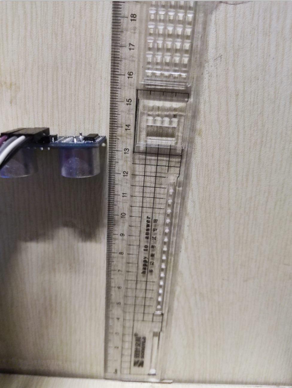
Ranging results
Test distance
Serial port debugging assistant

Serial port screen

Because I didn't use the timer for timing and the influence of the environment, there will be some errors.
The serial port knowledge involved in this article does not have too much text introduction, but only notes are written in the code. In fact, serial port communication is very simple. You only need to start the clock, use the input and output modes of two pins, and configure the relevant parameters. Because there are many contents in this article, there will be no too much introduction here. If you have the opportunity, Will be covered in later articles.
In solitude, a person should be like a team.
The author's ability level is limited, and there will inevitably be mistakes and mistakes in the article. Please don't hesitate to give advice. You are very welcome to exchange technology with poplar and learn technology together.