preface
This section will summarize STM32 (V)
Each IO of STM32 can be used as an interrupt input port for external interrupts, which is also the strength of STM32. The interrupt controller of STM32F103 supports 19 external interrupt / event requests. Each interrupt has a status
Bit, each interrupt / event has independent trigger and mask settings
--------------------
catalogue
1. Description of external interrupt
2. Introduction to exti interrupt
3. Take the rotary encoder as the course to introduce the code
--------------------
1, Introduction to external interrupt
(1) Interrupt system
Interrupt: during the operation of the main program, a specific interrupt trigger condition occurs, causing the CPU to suspend the currently running program and process the interrupt program. After completion, it returns to the original suspended position to continue working
Interrupt priority: when multiple interrupts start, the CPU will respond to more urgent interrupts according to the severity of things
Interrupt nesting: when an interrupt is running normally and a higher-level interrupt comes, it will first do the new high-level interrupt and then return in sequence
--------
(2) Interrupt of STM32
1. 68 maskable interrupt channels, including EXTI,TIM,ADC,USART,SPI,IIC,RTC and other peripherals
2. Use NVIC to uniformly manage interrupts. Each interrupt has 16 programmable priority levels, which can be grouped
(if we want to use interrupts, we must configure NVIC, which will be explained later)
--------
2, Introduction to EXTI external interrupt
1. EXTI can monitor the level signal of the specified GPIO port. When the level of the GPIO port changes, EXTI will immediately send an interrupt} application to the NVIC, and let the CPU execute the interrupt program after the decision of the NVIC
2. Trigger mode: rising edge (low to high), falling edge (high to low), bilateral edge (the first two are OK), software start (start by writing code, which has nothing to do with GPIO)
4. GPIO: all GPIO ports are supported, but the same Pin cannot trigger an interrupt
5. Number of channels: 16 pins (plus PVD output, RTC alarm clock, USB wake-up, Ethernet wake-up)
6. Trigger response mode: interrupt response, event response
Let's use the following photo to help us understand its basic structure
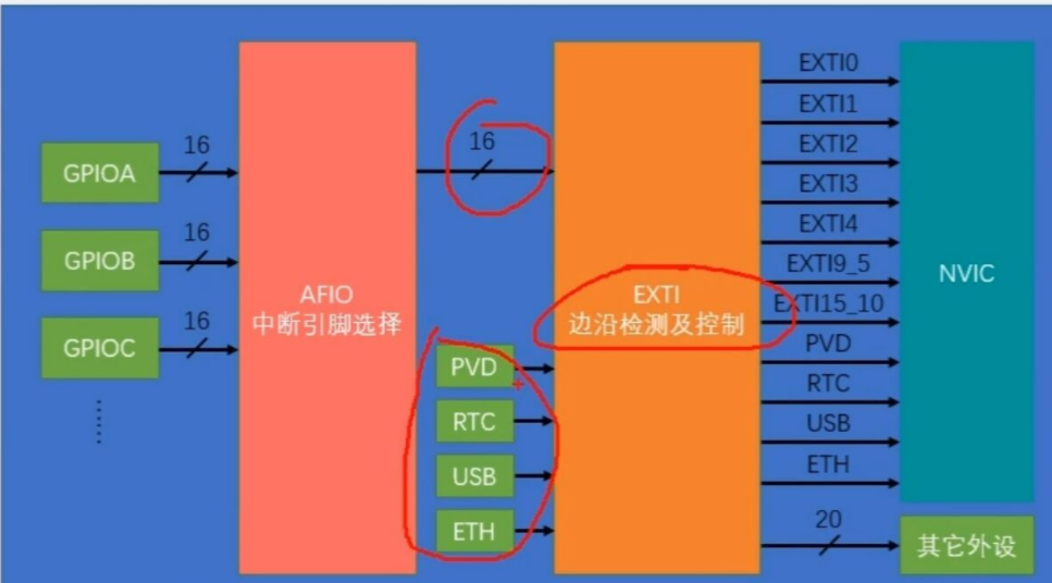
It should be noted that the same pin can only be used once, that is, only one port of PA0 and PB0 is interrupted
--------
(2) Brief introduction to AFIO
AFIO port mainly completes two tasks: multiplexing function, pin remapping and interrupt pin selection
(we also refer to the figure above)
--------
3, Take the rotary encoder as the course to introduce the code
1. What is rotary encoder?
Rotary encoder: a tool that can be used to measure the position in the speed direction. When it rotates, its output terminal can output the waveform corresponding to the speed direction
And it is through these waves that we program
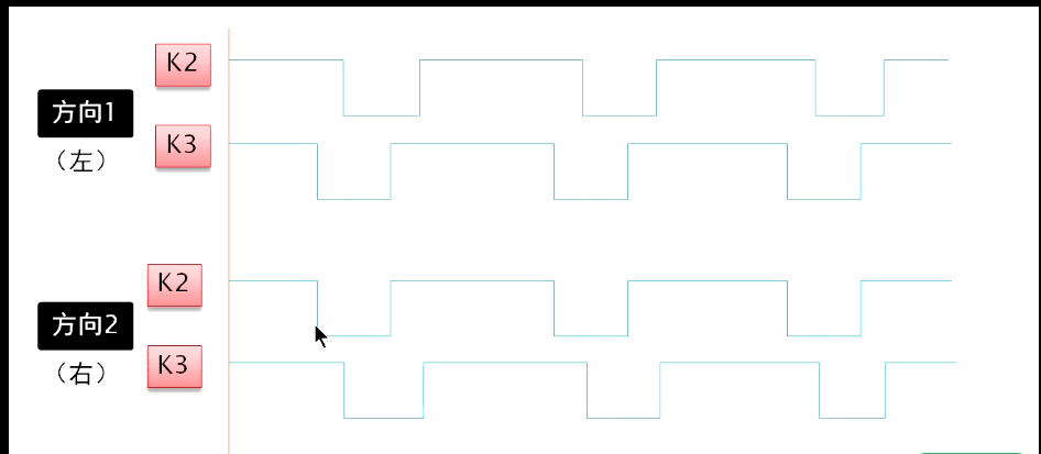
2. Waveform of rotary encoder
Knowing the waveform of rotary encoder is the key to our programming idea
3. Configuration of rotary encoder
The rotary encoder module has five pins, GND (-), VCC (+), SW, DT and CLK. VCC and GND are used to connect power and ground. According to the abbreviation, SW should be Switch, CLK is Clock and DT is Data
4. Programming ideas
Here, we will use the single thread method, that is, while reading the high and low levels of one wave with an interrupt, we will read the state of another wave level, so as to calculate the direction and times of rotation
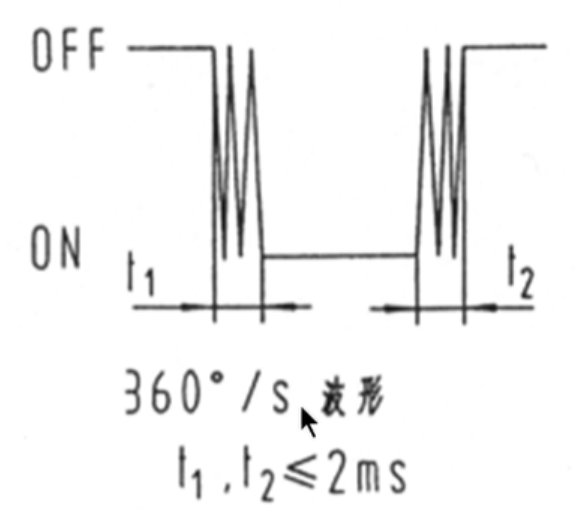
Of course, like normal mechanical buttons, we all have to shake
------------------
Programming part
As always, let's give our overall programming idea first
1 - initialize IO port as input.
2 -- turn on the multiplexing clock of the IO port and set the mapping relationship between the IO port and the interrupt line.
3 - initialize online interrupt, set trigger conditions, etc.
4 - configure interrupt packet (NVIC) and enable interrupt.
5 -- write interrupt service function
--------
First set our rotary encoder function - void Encoder_Init(void)
---------
1. Clock enable. The clocks of EXTI and NVIC are always on, so we don't need to turn them on again
	RCC_APB2PeriphClockCmd(RCC_APB2Periph_GPIOB, ENABLE);
	RCC_APB2PeriphClockCmd(RCC_APB2Periph_AFIO, ENABLE);
-------
2.GPIO initialization
	GPIO_InitTypeDef GPIO_InitStructure;
	GPIO_InitStructure.GPIO_Mode = GPIO_Mode_IPU;//Configured as pull-up mode
	GPIO_InitStructure.GPIO_Pin = GPIO_Pin_0 | GPIO_Pin_1;
	GPIO_InitStructure.GPIO_Speed = GPIO_Speed_50MHz;
	GPIO_Init(GPIOB, &GPIO_InitStructure);
Note here that we said earlier that our rotary encoder has five pins, but the middle key pin is not used here
------
3. Configure AFIO
 // GPIO_PinRemaConfig() can be used for pin remapping
	GPIO_EXTILineConfig(GPIO_PortSourceGPIOB, GPIO_PinSource0); //Configure the data selector of AFIO to select the pin we want and specify the external interrupt line
That is, we select PB0 as the interrupt port, PB0 as the interrupt source, and set our interrupt line
--------—
4. Configure EXIT
	EXTI_InitTypeDef EXTI_InitStructure;//Structure definition
	EXTI_InitStructure.EXTI_Line = EXTI_Line0 ;//We need to configure the interrupt line. We use line0 where PB0 is located
	EXTI_InitStructure.EXTI_LineCmd = ENABLE;//Open interrupt
	EXTI_InitStructure.EXTI_Mode = EXTI_Mode_Interrupt;//Interrupt mode
	EXTI_InitStructure.EXTI_Trigger =EXTI_Trigger_Rising_Falling ;//Set trigger mode
	EXTI_Init(&EXTI_InitStructure);//By calling this parameter, you can
Our interrupt trigger mode is selected according to our use. Here, we select the rising / falling edge trigger (in fact, both rising and falling can be selected)
---------
5. Configure NVIC
(write in front)
1. NVIC is a nested vector interrupt controller, which controls the functions related to the interrupt of the whole chip
2. NVIC is closely related to the kernel and is a peripheral in the kernel
We divide it into preemption and response. Preemption is greater than response. We give priority to the size of preemption (starting from 0, the smaller the first). When preemption is the same, we look at the response again. The comparison method is the same. High priority preemption can interrupt low priority preemption, but when preemption is the same, high priority response cannot interrupt low priority response
(1) Interrupt packet
NVIC_PriorityGroupConfig(NVIC_PriorityGroup_2);
(2) Initial configuration
	NVIC_InitTypeDef NVIC_InitStructure;
	NVIC_InitStructure.NVIC_IRQChannel = EXTI0_IRQn; //Select the triggered channel
	NVIC_InitStructure.NVIC_IRQChannelCmd = ENABLE; // Enable
	NVIC_InitStructure.NVIC_IRQChannelPreemptionPriority = 1;//Preemption Priority
	NVIC_InitStructure.NVIC_IRQChannelSubPriority = 1;//Response priority
	NVIC_Init(&NVIC_InitStructure);
-----------
6. Configuration of interrupt function
To read the value of the encoder, we need to return it, so we set two values here, one for recording and the other for returning
int16_t Encoder_Get(void)
{
	int16_t Temp;
	Temp = Encoder_Count;
	Encoder_Count = 0;
	return Temp;
}
Next, we enter our interrupt function
void EXTI0_IRQHandler(void)
{
	if (EXTI_GetITStatus(EXTI_Line0) == SET)//Judge an interrupt flag bit. If the interrupt is set to 1, the interrupt is triggered (the trigger mode is selected above), and enter the following if statement
	{
		if(GPIO_ReadInputDataBit(GPIOB,GPIO_Pin_0) == 1)//First judge the level of one of the waves
		{
			Delay_ms(3);//Remove jitter
			if(GPIO_ReadInputDataBit(GPIOB,GPIO_Pin_1) == 0)//Then judge the level state of the second wave
			{
				Encoder_Count --;
			}else{
				Encoder_Count ++;
			}

	}
-----------------
After writing the interrupt function, it becomes very simple. Next, we just need to display the numbers we rotate on the OLED
int16_t Num;

int main(void)
{
	OLED_Init();
	Encoder_Init();
	OLED_ShowString(1, 1, "Num:");

	while (1)
	{
		Num += Encoder_Get();
		OLED_ShowSignedNum(1, 5, Num, 3);
	}
}
--------------------