STM32F103 register mode turns on the LED water flow lamp
1, GPIO port initialization
You need to check the stm32 user manual here
Download link https://pan.baidu.com/s/1Q0jdfFsd39dN2aUyjaMXUw Extraction code zxwn
1. Clock configuration
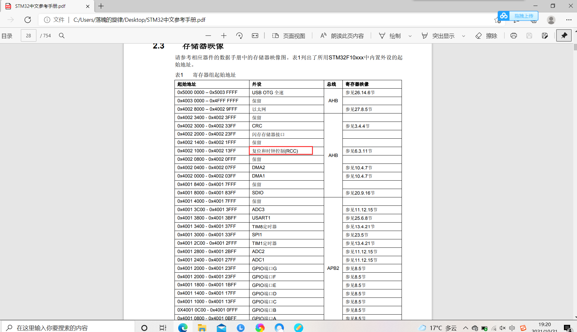
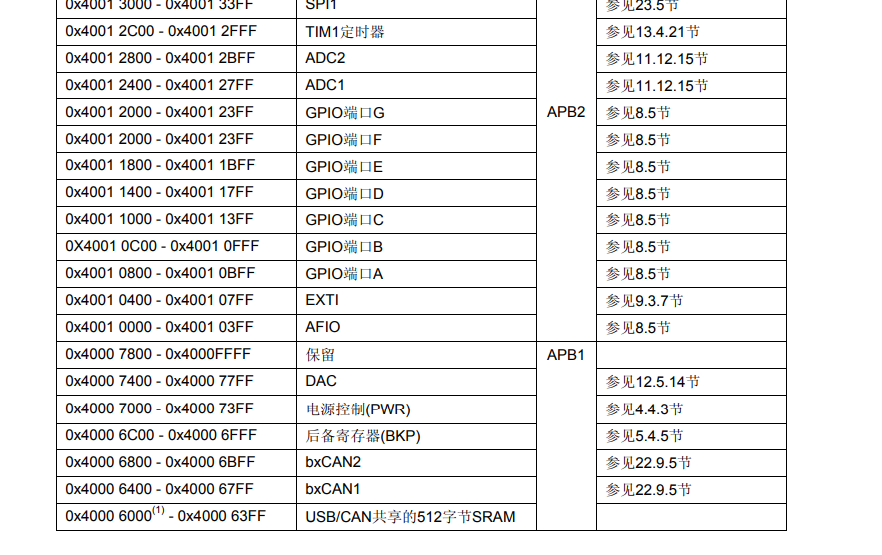
GPIOA, B and C ports are used in this experiment. All three ports belong to APB2 bus
1. Find the clock enable register mapping base address
2. Find the port offset address and the location of the corresponding port
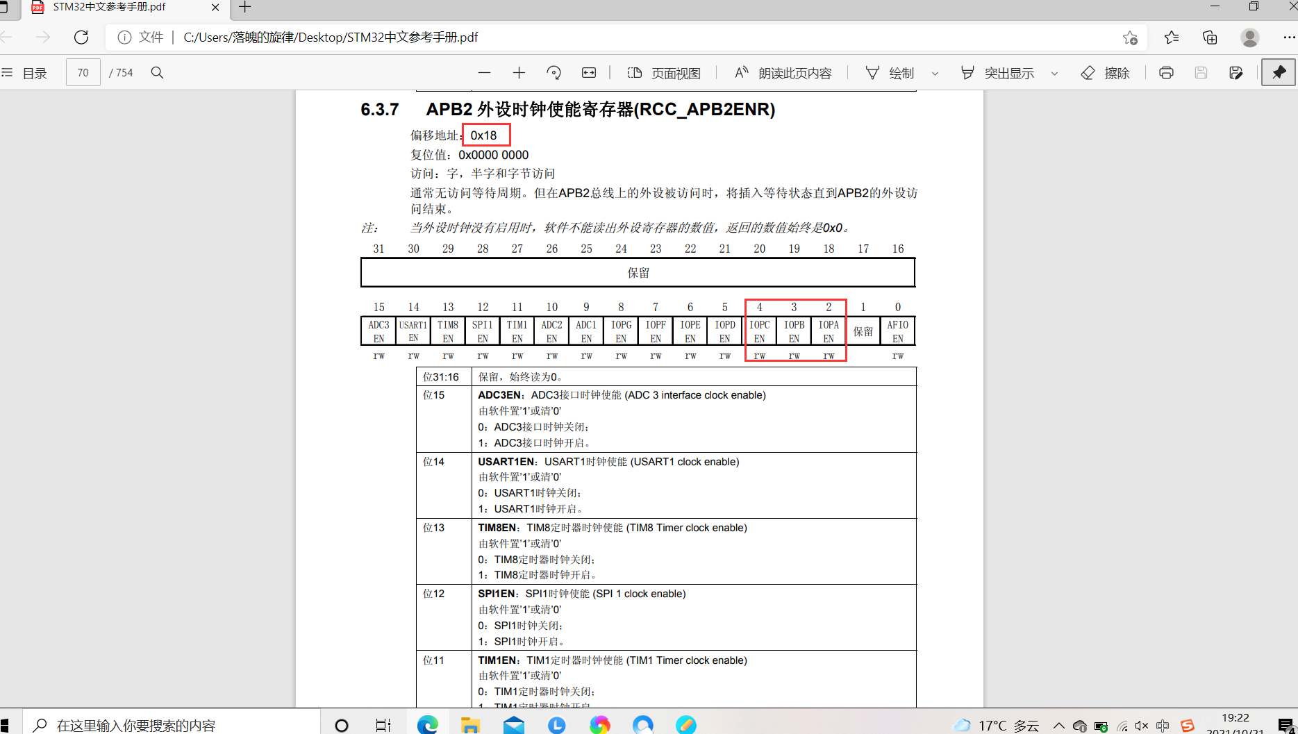
3. Enable the corresponding port clock
//----------------APB2 enable clock register---------------------
#define RCC_APB2ENR		*((unsigned volatile int*)0x40021018)

	RCC_APB2ENR|=1<<2|1<<3|1<<4;			//APB2-GPIOA, GPIOB, GPIOC peripheral clock enable
2. Input / output mode and output rate setting
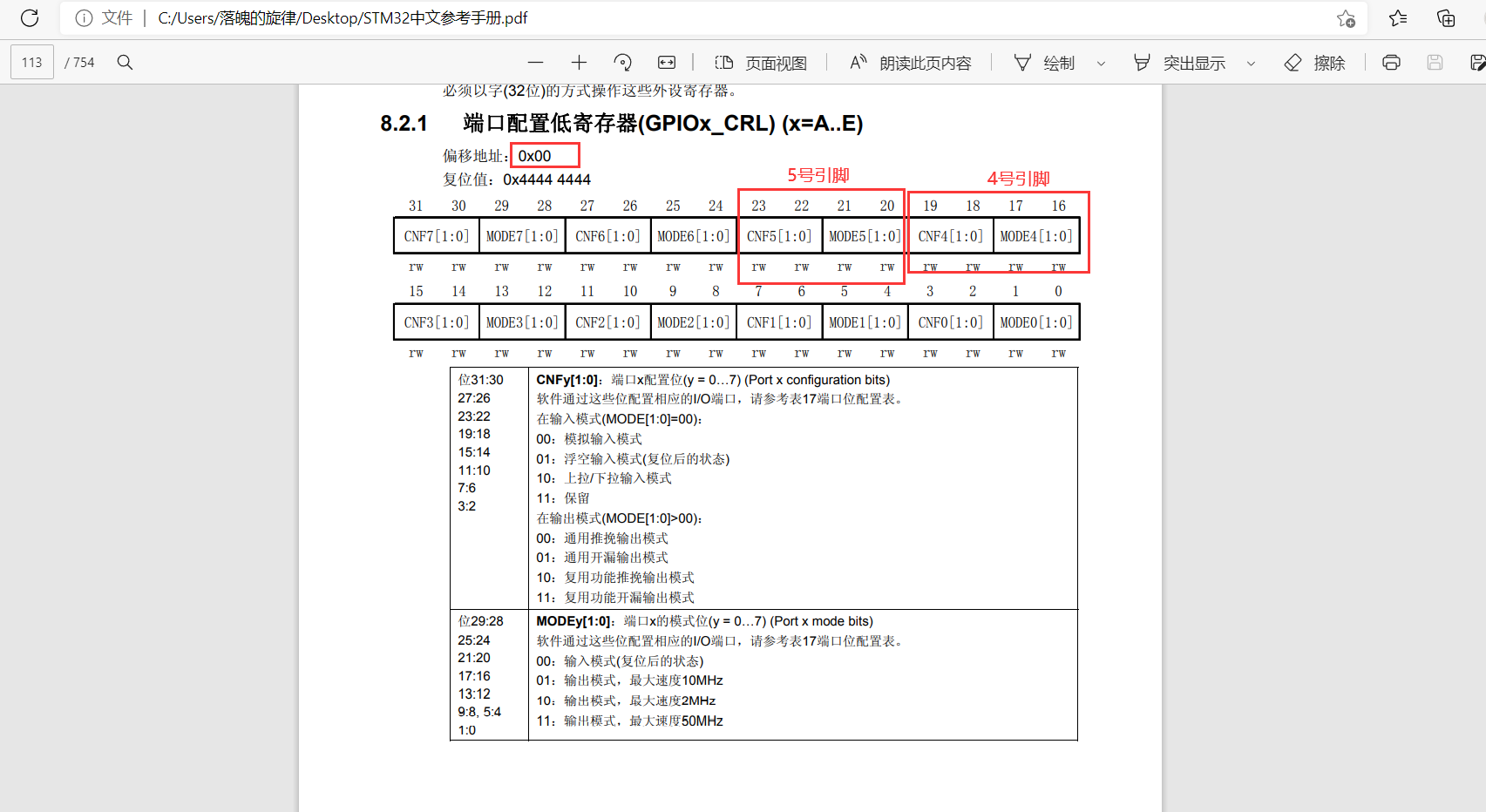
This experiment adopts the general push-pull output mode, and the maximum output clock frequency is 2Mhz. A4, B5 and C14 pins are used respectively. A4 and B5 belong to port configuration, the low register offset address is 0x00, and C13 belongs to port configuration, and the high register offset address is 0x04.
GPIOx port base address found
Configure the corresponding pin register, base address + offset
//----------------GPIOA configuration register-----------------------
#define GPIOA_CRL		*((unsigned volatile int*)0x40010800)
//----------------GPIOB configuration register-----------------------
#define GPIOB_CRL		*((unsigned volatile int*)0x40010C00)
//----------------GPIOC configuration register-----------------------
#define GPIOC_CRH		*((unsigned volatile int*)0x40011004)
Set the output mode as push-pull output and the output speed as 2Mhz
	GPIOA_CRL&=0xFFF0FFFF;		//Set bit reset
	GPIOA_CRL|=0x00020000;		//PA4 push-pull output changes bits 19, 18, 17 and 16 to 0010

	GPIOB_CRL&=0xFF0FFFFF;		//Set bit reset
	GPIOB_CRL|=0x00200000;		//PB5 push-pull output changes the 23rd, 22nd, 21st and 20th to 0010

	GPIOC_CRH&=0xFF0FFFFF;		//Set bit reset
	GPIOC_CRH|=0x00200000;		//PC14 push-pull output changes the 23rd, 22nd, 21st and 20th to 0010
2, Experimental process
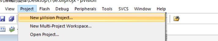
1. keil compiler
1. Click Project to create a new Project file
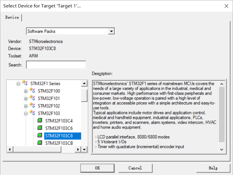
2. Name the project, select STM32F103C8, and click OK
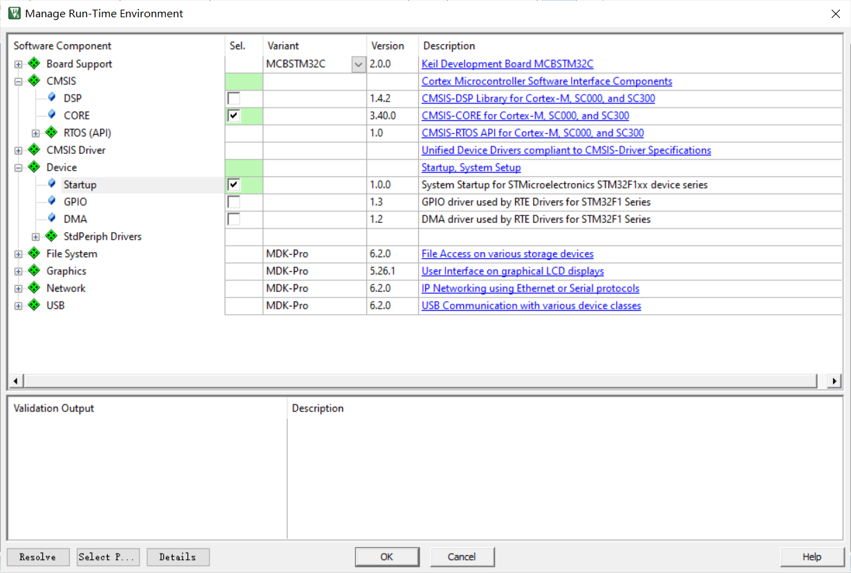
3. Check core in CMSIS, check Statuo under device, and click OK
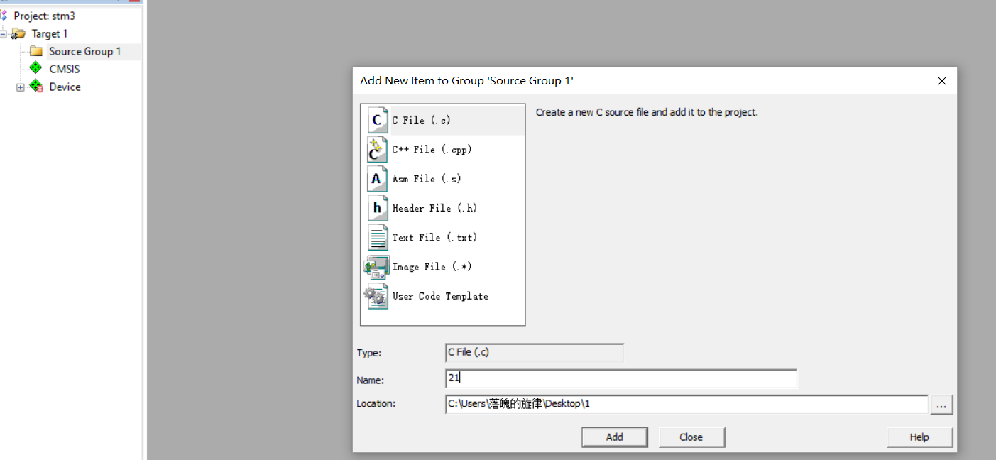
4. Click the + sign on the left of Target 1, right-click Source Group 1, select Add new item, and select generate. c file.
c language code
#include "stm32f10x.h"
//----------------APB2 enable clock register---------------------
#define RCC_APB2ENR		*((unsigned volatile int*)0x40021018)
//----------------GPIOA configuration register-----------------------
#define GPIOA_CRL		*((unsigned volatile int*)0x40010800)
#define	GPIOA_ODR		*((unsigned volatile int*)0x4001080C)
//----------------GPIOB configuration register-----------------------
#define GPIOB_CRL		*((unsigned volatile int*)0x40010C00)
#define	GPIOB_ODR		*((unsigned volatile int*)0x40010C0C)
//----------------GPIOC configuration register-----------------------
#define GPIOC_CRH		*((unsigned volatile int*)0x40011004)
#define	GPIOC_ODR		*((unsigned volatile int*)0x4001100C)


//Delay Functions
 void Delay()
 {
   u32 i=0;
   for(;i<5000000;i++);
 }
 int main(void)
 {
	RCC_APB2ENR|=1<<2|1<<3|1<<4;			//APB2-GPIOA, GPIOB, GPIOC peripheral clock enable

	GPIOA_CRL&=0xFFF0FFFF;		//Set bit reset
	GPIOA_CRL|=0x00020000;		//PB5 push pull output
	GPIOA_ODR&=~(1<<4);			//Set the initial light to off

	GPIOB_CRL&=0xFF0FFFFF;		//Set bit reset
	GPIOB_CRL|=0x00200000;		//PB5 push pull output
	GPIOB_ODR&=~(1<<5);			//Set the initial light to off

	GPIOC_CRH&=0xF0FFFFFF;		//Set bit reset
	GPIOC_CRH|=0x02000000;		//PB5 push pull output
	GPIOC_ODR&=~(1<<14);			//Set the initial light to off


	while(1){
		//A lamp
		GPIOA_ODR|=1<<4;		//PB5 high level
	 	Delay();
		GPIOA_ODR&=~(1<<4);		//PB5 low level is set to 0, so press bit and


		//B lamp
		GPIOB_ODR|=1<<5;		//PB5 high level
	 	Delay();
		GPIOB_ODR&=~(1<<5);		//PB5 low level is set to 0, so press bit and


		//C lamp
		GPIOC_ODR|=1<<14;		//PB5 high level
	 	Delay();
		GPIOC_ODR&=~(1<<14);		//PB5 low level is set to 0, so press bit and


		}
}
Assembly code (I completed this experiment with c language code)
 AREA MYDATA, DATA

 AREA MYCODE, CODE
	ENTRY
	EXPORT led

led
	;Enable A,B,C
    ldr r0, =0x40021018
    ldr r1, =0x0000001c
    str r1, [r0]


	;configure port A4
	ldr r0, =0x40010800
    ldr r1, [r0]
    bic r1, r1, #0x000f0000
    orr r1, r1, #0x00010000
    str r1, [r0]

	;configure port B5
    ldr r0, =0x40010c00
    ldr r1, [r0]
    bic r1, r1, #0x00f00000
    orr r1, r1, #0x00100000
    str r1, [r0]

	;configure port C14
	ldr r0, =0x40011004
    ldr r1, [r0]
    bic r1, r1, #0x0f000000
    orr r1, r1, #0x01000000
    str r1, [r0]

	;Initially A4 Light up
	ldr r0, =0x4001080c
    ldr r1, =0x00000010
    str r1, [r0]

	ldr r0, =5000000;frequency
    ldr r1, =0

;Cycle light
blink
    add r1, r1, #1
    cmp r1, r0
    blt blink

	;A4 Extinguish
	ldr r1, =0x4001080c
    ldr r2, [r1]
    eor r2, r2, #0x00000010
    str r2, [r1]

	;B5 bright
	ldr r1, =0x40010c0c
    ldr r2, [r1]
    eor r2, r2, #0x00000020
    str r2, [r1]

	ldr r1, =0

blink1
	add r1, r1, #1
    cmp r1, r0
    blt blink1

	;B5 Extinguish
	ldr r1, =0x40010c0c
    ldr r2, [r1]
    eor r2, r2, #0x00000020
    str r2, [r1]

	;C14 bright
	ldr r1, =0x4001100c
    ldr r2, [r1]
    eor r2, r2, #0x00004000
    str r2, [r1]


	ldr r1, =0

blink2
	add r1, r1, #1
    cmp r1, r0
    blt blink2

	;C14 Extinguish
	ldr r1, =0x4001100c
    ldr r2, [r1]
    eor r2, r2, #0x00004000
    str r2, [r1]

	;A4 bright
	ldr r1, =0x4001080c
    ldr r2, [r1]
    eor r2, r2, #0x00000010
    str r2, [r1]


	ldr r1, =0
    b blink


	END
Then click the magic wand and select great hex file
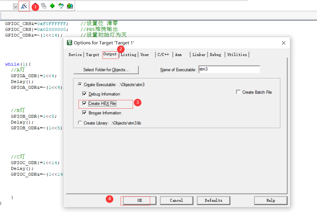
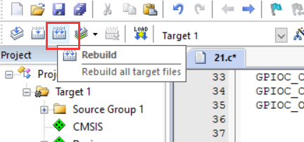
Click Rebuild
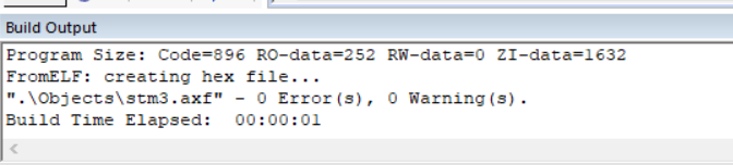
The program can generate HEX file without error
2. Burning operation
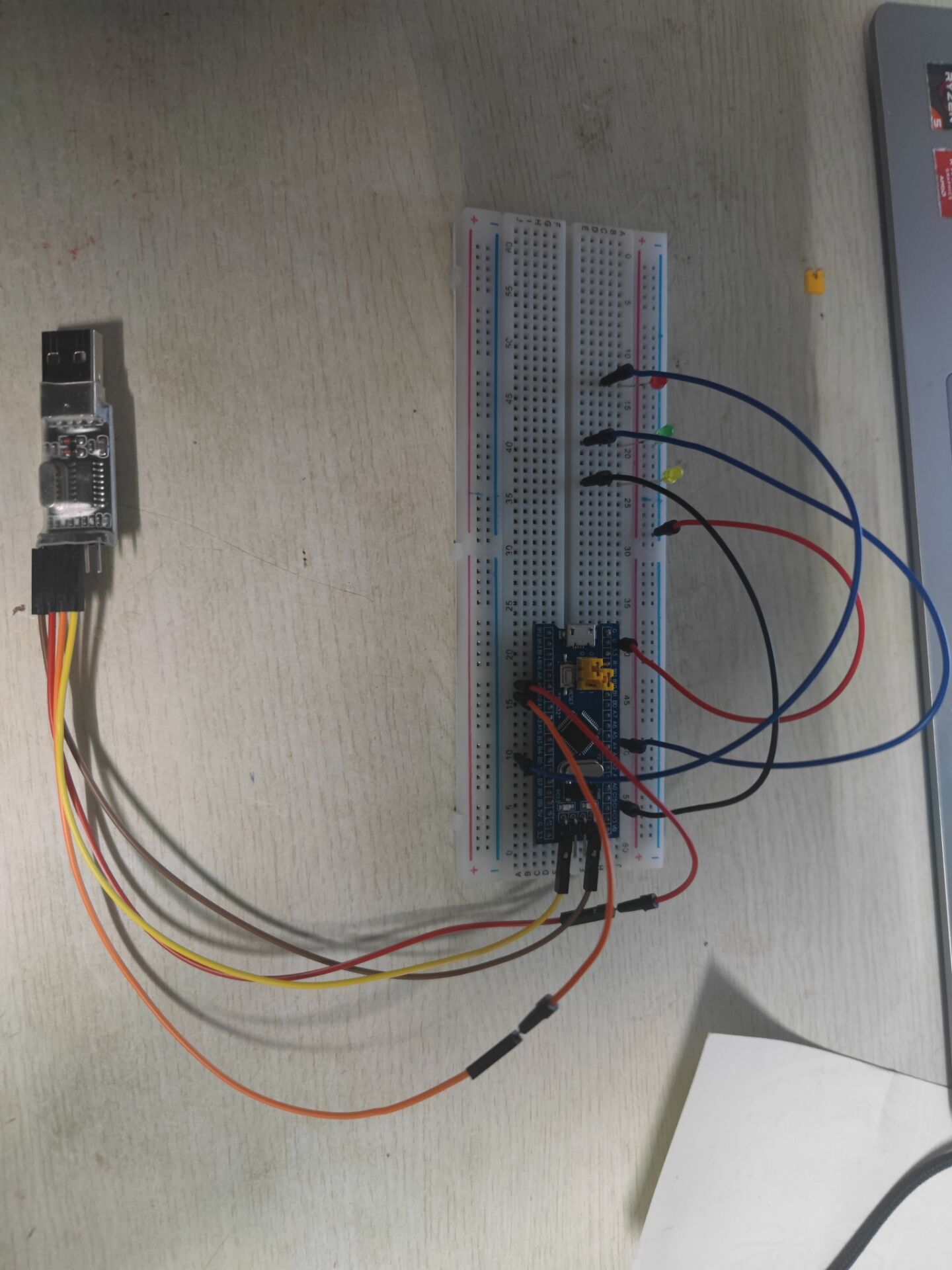
1) Connecting line
equipment
stm32 core board 103f
usb transfer interface
One red, yellow and green LED and several wires
Line connection
GND-G
3V3-3.3
RXD-A9
TXD-A10
Set B00T0 to 1, BOOT1 to 0, and press reset
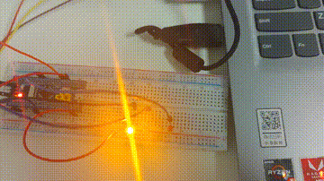
GPIO and LED connections
A4 of GPIOA, B5 of GPIO and C14 of GPIO are connected to the positive poles of three LED lamps. Just connect three lights.
Connection diagram
2) Burn
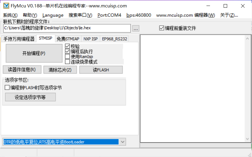
Insert the USB to TTL module into the computer, open mcuisp, click the search serial port, then upload the previously generated hex file, select the low level reset of DTR, and the high level of RTs into BootLoader
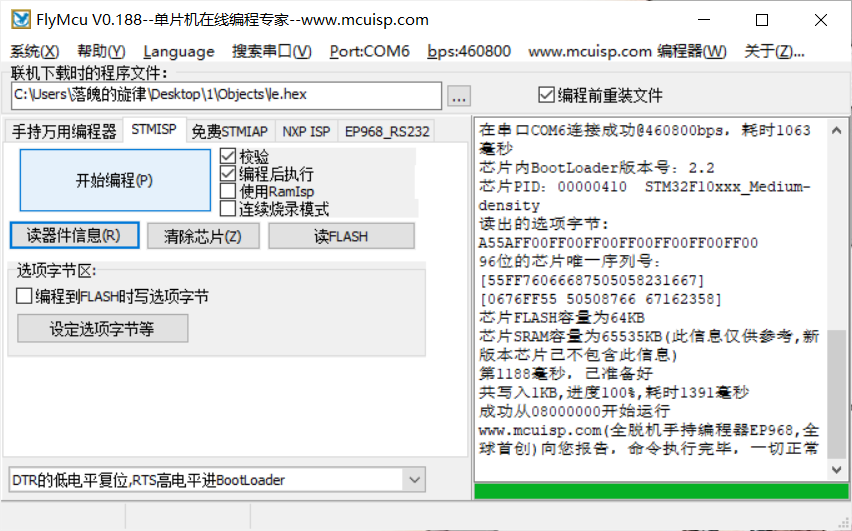
Click to read the device information and click to start programming. If successful, everything will appear on the right.
3) Water lamp effect
3, Summary
Through this experiment, I have a deeper understanding of STM32. At the same time, I learned to use it to light LED lights. Due to many difficulties encountered in the process of using STM32 for the first time, there are always errors in Keil compilation. In reality, Project cannot be generated. Only after consulting and knowing that it is a computer account and the user name is Chinese, baidu finally found a method. There was also a problem when connecting the board and it couldn't be burned. Finally, it was found that it was a connection error. After discovery, it was burned successfully, but finally, there was a problem with the light. After inspection, it was found that the problem was found. The board was in poor contact. Just press it a little.
4, References
https://blog.csdn.net/geek_monkey/article/details/86291377
https://blog.csdn.net/qq_60678931/article/details/120753360