Based on the first two USART serial communication, this paper uses DMA controller to realize serial communication
1, DMA
1. Introduction to DMA
The full name of DMA is Direct Memory Access, that is, Direct Memory Access.
Direct memory access (DMA) is used to provide high-speed data transmission between peripherals and memory or between memory and memory. The DMA transmission mode does not require the CPU to directly control the transmission, nor does it retain the field and reply to the field process like the interrupt processing mode. A straight-line data transmission channel is opened for RAM and IO equipment through hardware, which greatly improves the efficiency of the CPU. DMA transfers copy data from one address space to another. When the CPU initializes the transfer action, the transfer action itself is implemented and completed by the DMA controller.
STM32F1 has at most 2 DMA controllers. DMA2 only exists in high-capacity products. Dma1 has 7 channels and DMA2 has 5 channels. Each channel is dedicated to managing requests for memory access from one or more peripherals. There is also an arbitration to coordinate the priority of DMA requests. The block diagram of DMA is given on page 144 of STM32 Chinese reference manual.
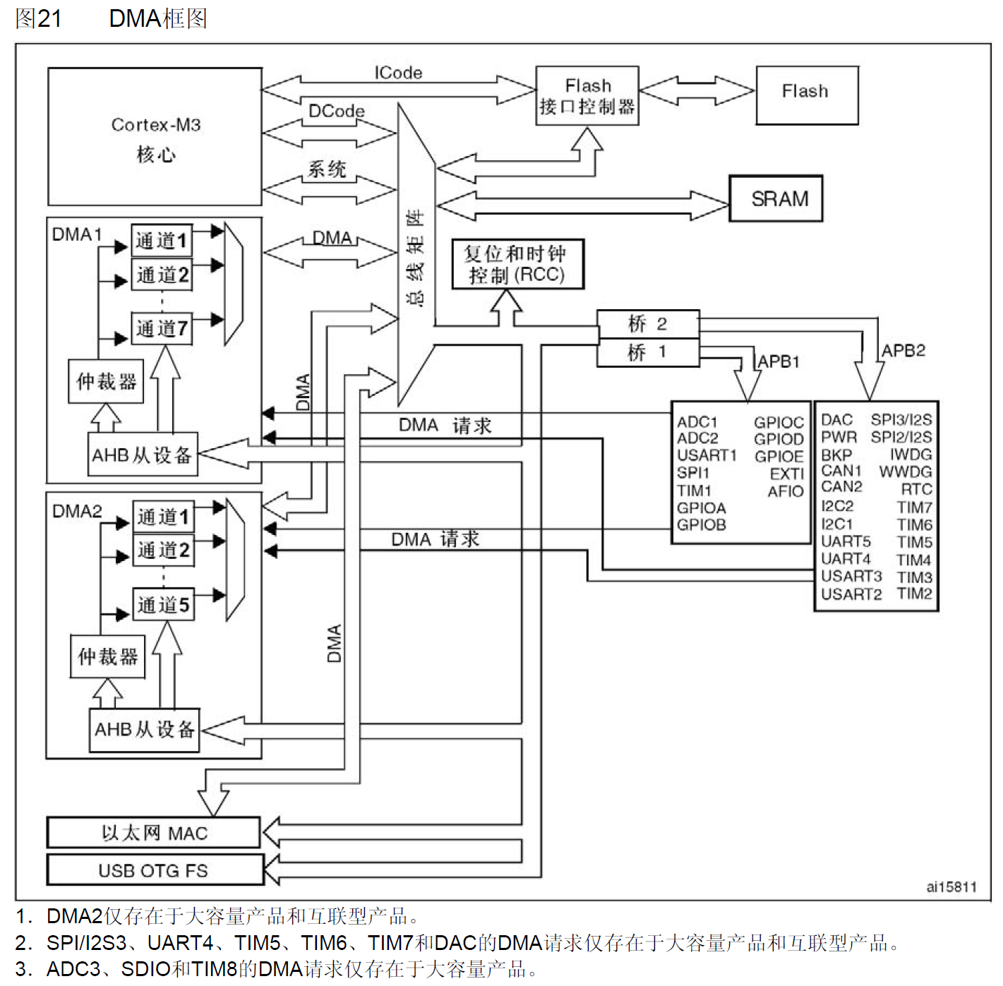
2. Main characteristics of DMA
The main features of DMA are introduced in detail on page 142 of STM32 Chinese reference manual
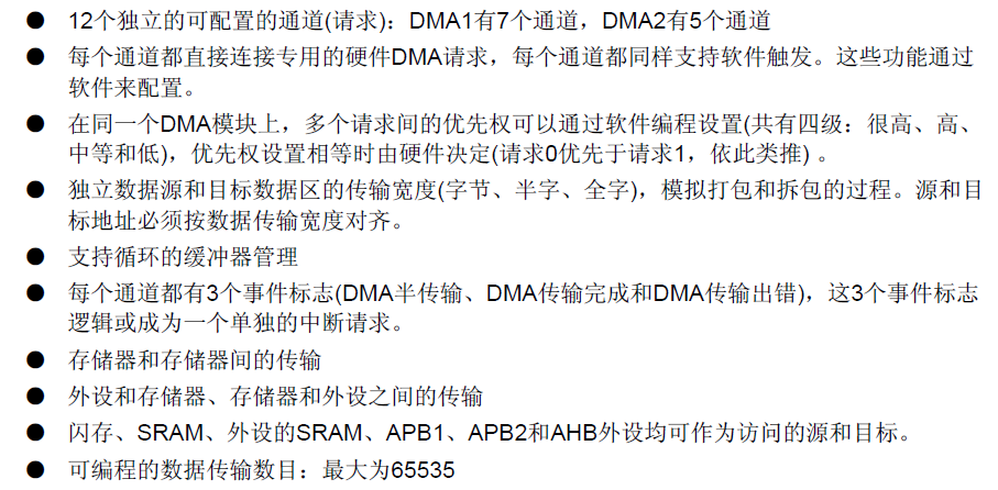
The following takes DMA1 controller as an example
Seven requests generated from peripherals (TIMx[x=1, 2, 3, 4], ADC1, SPI1, SPI/I2S2, I2Cx[x=1, 2] and USARTx[x=1, 2, 3]) are input to the DMA1 controller through logic or, which means that only one request can be valid at the same time.
The DMA request of the peripheral can be turned on or off independently by setting the control bit in the corresponding peripheral register.
The relevant DMA1 controller information is introduced on page 147 of STM32 Chinese reference manual.
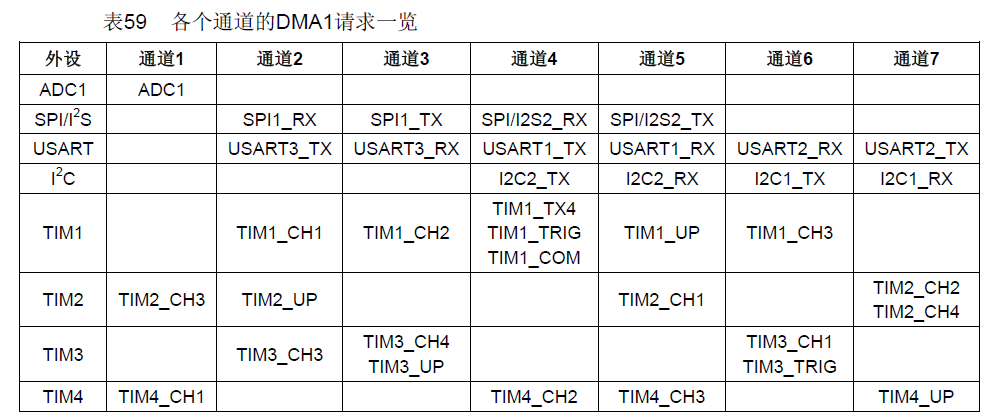
When an event occurs, the peripheral sends a request signal to the DMA controller. The DMA controller processes the request according to the priority of the channel. When the DMA controller starts to access the requested peripheral, the DMA controller immediately sends it a reply signal. When a reply signal is received from the DMA controller, the peripheral immediately releases its request. Once the peripheral releases the request, the DMA controller cancels the response signal at the same time. If there are more requests, the peripheral can start the next cycle.
In short, each DMA transfer consists of three operations.

The arbiter needs to be set to start the access of peripheral / memory according to the priority of channel request.
Priority management is divided into two stages:
- Software: the priority of each channel can be in DMA_ Set in ccrx register, there are four levels: highest priority, high priority, medium priority and low priority
- Hardware: if two requests have the same software priority, the lower numbered channel has higher priority than the higher numbered channel. For example, channel 2 takes precedence over channel 4.
Note: in high-capacity and interconnected products, DMA1 controller has higher priority than DMA2 controller
DMA channel each channel can perform DMA transfer between fixed address peripheral register and memory address.
There are many knowledge materials and knowledge about DMA. For details, you can check the relevant information in the STM32 Chinese reference manual. The following takes the common code as an example and combines the previous serial port experiment
3. Partial code principle
Or the old routine before, first define the structure
DMA_InitTypeDef DMA_InitStructure;
Then the clock is enabled, and then the content in the structure
typedef struct
{
  uint32_t DMA_PeripheralBaseAddr; /*!< Specifies the peripheral base address for DMAy Channelx. */

  uint32_t DMA_MemoryBaseAddr;     /*!< Specifies the memory base address for DMAy Channelx. */

  uint32_t DMA_DIR;                /*!< Specifies if the peripheral is the source or destination.
                                        This parameter can be a value of @ref DMA_data_transfer_direction */

  uint32_t DMA_BufferSize;         /*!< Specifies the buffer size, in data unit, of the specified Channel.
                                        The data unit is equal to the configuration set in DMA_PeripheralDataSize
                                        or DMA_MemoryDataSize members depending in the transfer direction. */

  uint32_t DMA_PeripheralInc;      /*!< Specifies whether the Peripheral address register is incremented or not.
                                        This parameter can be a value of @ref DMA_peripheral_incremented_mode */

  uint32_t DMA_MemoryInc;          /*!< Specifies whether the memory address register is incremented or not.
                                        This parameter can be a value of @ref DMA_memory_incremented_mode */

  uint32_t DMA_PeripheralDataSize; /*!< Specifies the Peripheral data width.
                                        This parameter can be a value of @ref DMA_peripheral_data_size */

  uint32_t DMA_MemoryDataSize;     /*!< Specifies the Memory data width.
                                        This parameter can be a value of @ref DMA_memory_data_size */

  uint32_t DMA_Mode;               /*!< Specifies the operation mode of the DMAy Channelx.
                                        This parameter can be a value of @ref DMA_circular_normal_mode.
                                        @note: The circular buffer mode cannot be used if the memory-to-memory
                                              data transfer is configured on the selected Channel */

  uint32_t DMA_Priority;           /*!< Specifies the software priority for the DMAy Channelx.
                                        This parameter can be a value of @ref DMA_priority_level */

  uint32_t DMA_M2M;                /*!< Specifies if the DMAy Channelx will be used in memory-to-memory transfer.
                                        This parameter can be a value of @ref DMA_memory_to_memory */
}DMA_InitTypeDef;
The STM32 firmware library user manual gives a description of the relevant parameters on page 89
- DMA_PeripheraBaseAddr: this parameter is used to define the base address of DMA peripheral
- DMA_MemoryBaseAddr: this parameter is used to define the DMA memory base address
- DMA_DIR: DMA_ Dir specifies whether the peripheral is used as the destination or source of data transmission. The following table shows the value range of this parameter.

- DMA_BufferSize: DMA_ Buffersize is used to define the DMA cache size of the specified DMA channel, in bits and data units. According to the transmission direction, the data unit is equal to the parameter DMA in the structure_ Peripheraldatasize or DMA parameter_ Value of memorydatasize
- DMA_PeripheralInc: DMA_ Peripheralnc is used to set whether the peripheral address register is incremented. The following table shows the value range of this parameter

- DMA_MemoryInc: DMA_ Memoryinc is used to set whether the memory address register is incremented or not.

- DMA_PeripheralDataSize: DMA_ Peripheraldatasize sets the peripheral data width. The following table shows the value range of this parameter

- DMA_MemoryDataSize: DMA_ Memorydatasize sets the peripheral data width. The following table shows the value range of this parameter

- DMA_Mode: DMA_ Mode sets the working mode of CAN. The following table shows the values that CAN be taken for this parameter

- DMA_Priority: DMA_ Priority sets the software priority of DMA channel x. The following table shows the values that can be taken for this parameter

- DMA_M2M: DMA_ M2M enables memory to memory transfer of DMA channel. The following table shows the values that can be taken for this parameter

Therefore, our structure is defined as follows
DMA1_MEM_LEN = TEXT_LENTH+2;
DMA_InitStructure.DMA_BufferSize = TEXT_LENTH+2;						//Size of DMA cache for DMA channel
DMA_InitStructure.DMA_DIR = DMA_DIR_PeripheralDST;						//Data transmission direction, read from memory and sent to peripherals
DMA_InitStructure.DMA_M2M = DMA_M2M_Disable;							//DMA channel is not set for memory to memory transfer
DMA_InitStructure.DMA_MemoryBaseAddr = (u32)SendBuff;					//DMA memory base address
DMA_InitStructure.DMA_MemoryDataSize = DMA_MemoryDataSize_Byte;			//The data width is 8 bits
DMA_InitStructure.DMA_MemoryInc = DMA_MemoryInc_Enable;					//Memory address register increment
DMA_InitStructure.DMA_Mode = DMA_Mode_Normal;							//Working in normal cache mode
DMA_InitStructure.DMA_PeripheralBaseAddr = (u32)&USART1->DR;			//DMA peripheral base address
DMA_InitStructure.DMA_PeripheralDataSize = DMA_PeripheralDataSize_Byte;	//The data width is 8 bits
DMA_InitStructure.DMA_PeripheralInc = DMA_PeripheralInc_Disable;		//Peripheral address register unchanged
DMA_InitStructure.DMA_Priority = DMA_Priority_Medium;					//DMA channel has medium priority
Then DMA initialization
DMA_Init(DMA1_Channel4,&DMA_InitStructure);
Here, we choose USART1. Combined with table 59 above, we know that channel 4, dma1, should be selected_ Channel4
In the main.c main program, after we enable DMA, we also need to start DMA transmission. Here we add void mydma to dma.c_ Enable (void) function to start a DMA transfer
void MyDMA_Enable()
{
	DMA_Cmd(DMA1_Channel4,DISABLE);						//Turn off USART_ Tx_ Channel indicated by dma1
	DMA_SetCurrDataCounter(DMA1_Channel4,DMA1_MEM_LEN);	//Size of DMA cache for DMA channel
	DMA_Cmd(DMA1_Channel4,ENABLE);						//Enable usart1_ Tx_ Channel indicated by dma1
}
Finally, don't forget to add a DMA request to enable USART1 in the main program
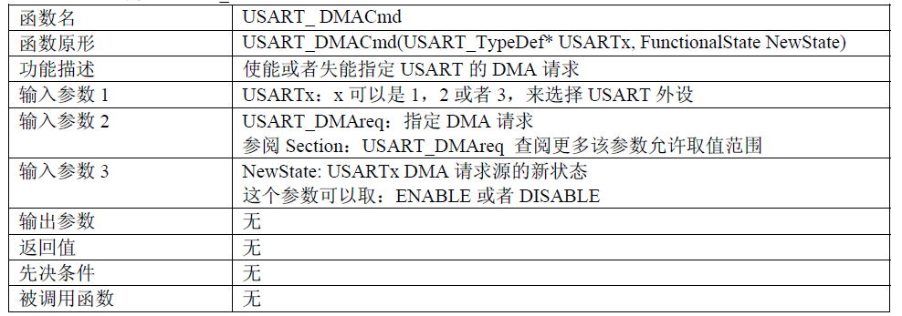
USART_DMACmd(USART1,USART_DMAReq_Tx,ENABLE);
The instructions for using this function are as follows
2, Experimental code
dma.h
#ifndef __DMA_H
#define __DMA_H
#include "stm32f10x.h"
void MyDMA_Init(void);
void MyDMA_Enable(void);
#endif
dma.c
#include "dma.h"
DMA_InitTypeDef DMA_InitStructure;
const u8 TEXT_TO_SEND[]={"Hello,world!"};
#define TEXT_LENTH sizeof(TEXT_TO_SEND)-1
u8 SendBuff[TEXT_LENTH+2];
u16 DMA1_MEM_LEN;

void MyDMA_Init()
{
	u16 i;
	RCC_AHBPeriphClockCmd(RCC_AHBPeriph_DMA1,ENABLE);

	DMA_DeInit(DMA1_Channel4);
	DMA1_MEM_LEN = TEXT_LENTH+2;
	DMA_InitStructure.DMA_BufferSize = TEXT_LENTH+2;						//Size of DMA cache for DMA channel
	DMA_InitStructure.DMA_DIR = DMA_DIR_PeripheralDST;						//Data transmission direction, read from memory and sent to peripherals
	DMA_InitStructure.DMA_M2M = DMA_M2M_Disable;							//DMA channel is not set for memory to memory transfer
	DMA_InitStructure.DMA_MemoryBaseAddr = (u32)SendBuff;					//DMA memory base address
	DMA_InitStructure.DMA_MemoryDataSize = DMA_MemoryDataSize_Byte;			//The data width is 8 bits
	DMA_InitStructure.DMA_MemoryInc = DMA_MemoryInc_Enable;					//Memory address register increment
	DMA_InitStructure.DMA_Mode = DMA_Mode_Normal;							//Working in normal cache mode
	DMA_InitStructure.DMA_PeripheralBaseAddr = (u32)&USART1->DR;			//DMA peripheral base address
	DMA_InitStructure.DMA_PeripheralDataSize = DMA_PeripheralDataSize_Byte;	//The data width is 8 bits
	DMA_InitStructure.DMA_PeripheralInc = DMA_PeripheralInc_Disable;		//Peripheral address register unchanged
	DMA_InitStructure.DMA_Priority = DMA_Priority_Medium;					//DMA channel has medium priority
	DMA_Init(DMA1_Channel4,&DMA_InitStructure);								//According to DMA_ Initialize the DMA channel USART with the parameters specified in initsturct_ Tx_ DMA_ Register identified by channel

	//send content
	for(i=0;i<TEXT_LENTH;i++)
	{
		SendBuff[i]=TEXT_TO_SEND[i];
	}
	SendBuff[TEXT_LENTH]=0x0d;
	SendBuff[TEXT_LENTH+1]=0x0a;
}

/* Start a DMA transfer */
void MyDMA_Enable()
{
	DMA_Cmd(DMA1_Channel4,DISABLE);						//Turn off USART_ Tx_ Channel indicated by dma1
	DMA_SetCurrDataCounter(DMA1_Channel4,DMA1_MEM_LEN);	//Size of DMA cache for DMA channel
	DMA_Cmd(DMA1_Channel4,ENABLE);						//Enable usart1_ Tx_ Channel indicated by dma1
}
main.c
#include "stm32f10x.h"
#include "delay.h"
#include "usart.h"
#include "dma.h"
int main(void)
{
	delay_init();
	MyUSART_Init();
	MyDMA_Init();
	while(1)
	{
		USART_DMACmd(USART1,USART_DMAReq_Tx,ENABLE);	//Serial port - DMA enable
		MyDMA_Enable();									//Start MDA transfer
		while(1)
		{
			if(DMA_GetFlagStatus(DMA1_FLAG_TC4)!=RESET)	//Wait for channel 4 transmission to complete
			{
				DMA_ClearFlag(DMA1_FLAG_TC4);			//Clear channel 4 transmission completion flag
				break;
			}
		}
		delay_ms(1000);									//Delay 1s
	}
}
3, Experimental results
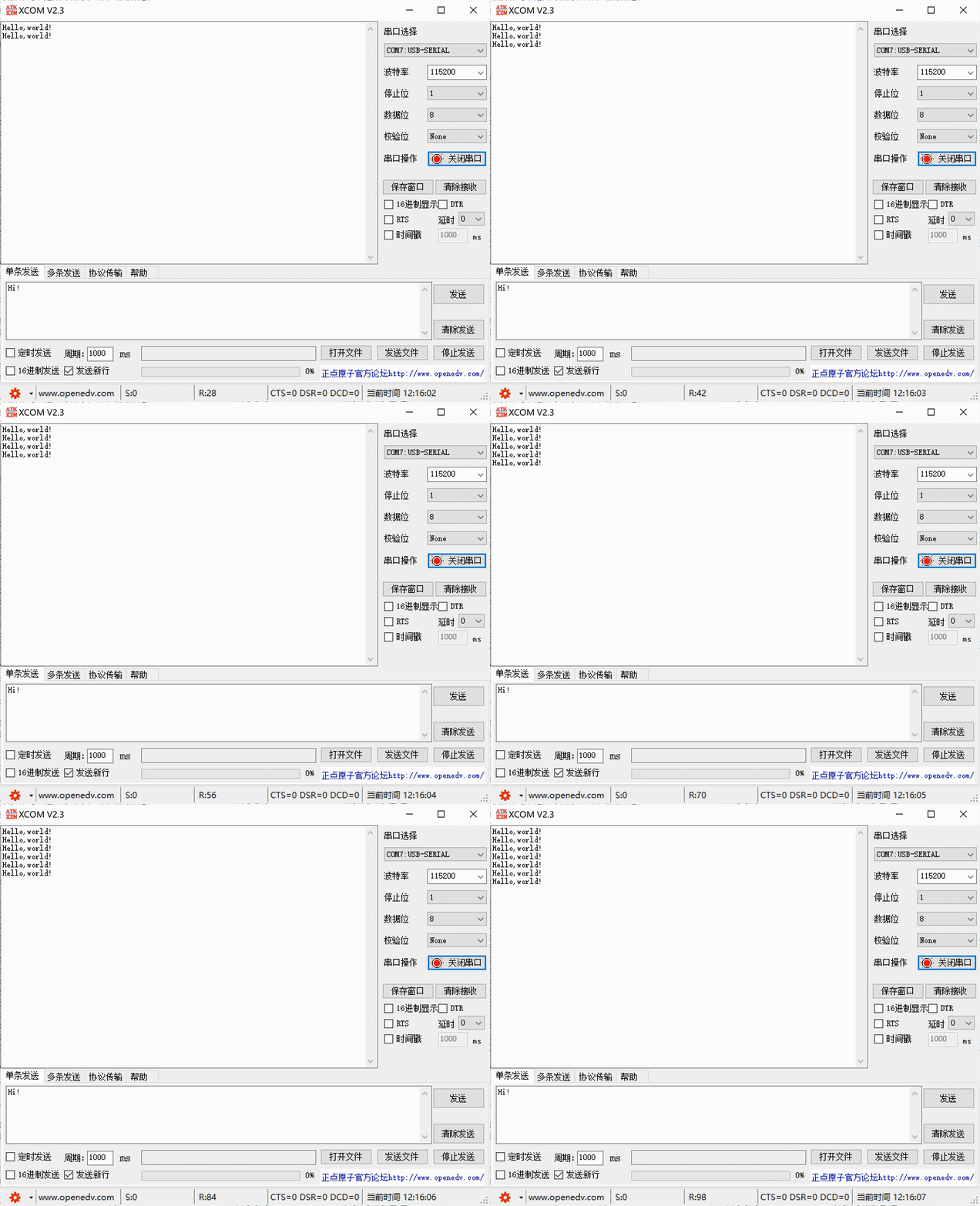
4, Summary
In this experiment, DMA controller is simply used, and there are many DMA parameters. Due to space limitation (too much content QAQ), please refer to STM32 Chinese reference manual for detailed knowledge introduction.
5, References
[punctual atom] STM32 development board experiment course (F103)_ Beep beep beep_ bilibili