STM32F103 Mini transplant RT thread nano
Introduction to RT thread nano
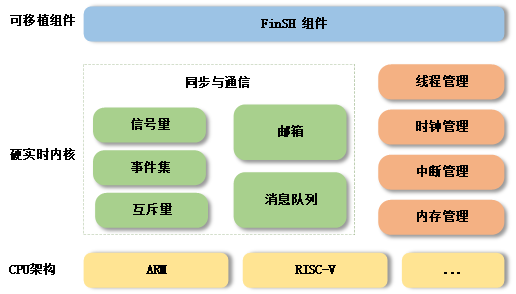
RT thread nano is a minimalist version of hard real-time kernel. It is developed by C language, adopts object-oriented programming thinking and has a good code style. It is a tailorable, preemptive real-time multitasking RTOS. Its memory resources are very small, and its functions include relatively complete real-time operating system characteristics such as task processing, software timer, semaphore, mailbox and real-time scheduling. It is suitable for 32-bit ARM entry-level MCU widely used in home appliances, consumer electronics, medical equipment, industrial control and other fields.
The following figure is the software block diagram of RT thread nano, including supported CPU architecture and kernel source code, as well as removable fish components:
Use Nano source code compressed package for migration
RT-Thread Nano3.1.3 source code download link
RT thread nano source directory structure
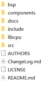
bsp: official sample code and board level support files
Components: find components
docs: official documentation
include: header file of kernel
Libcpu: migration file of arm series and RISC-V series CPU s
SRC: nano kernel source code
Prepare an STM32 bare metal project
Here is the change based on the bare metal code in the STM32F103 Mini board data of punctual atom, and the project link completed by the change will be attached.
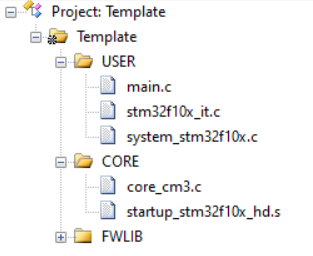
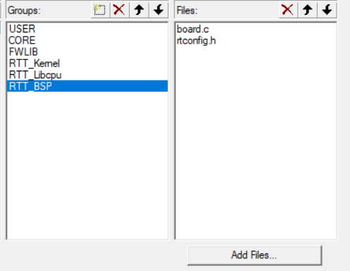
Firstly, delete the useless groups in the project groups, leaving only the ones in the figure
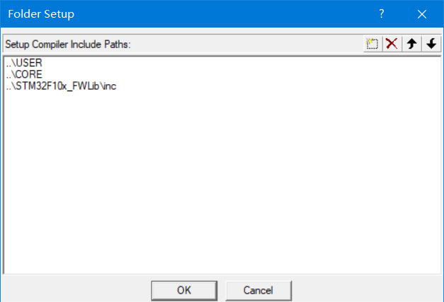
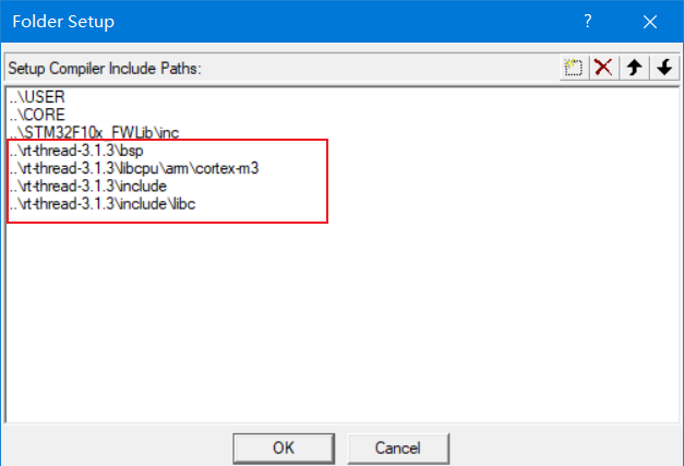
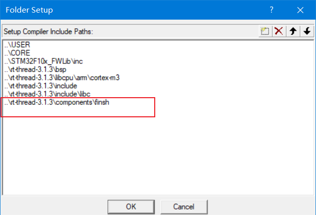
Delete the useless header file path and keep only the in the figure
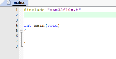
Empty main C procedures in documents
Add RT thread nano kernel code
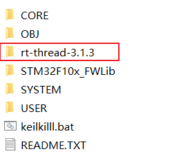
RT to be downloaded_ Copy the kernel source code of thread nano to the project directory
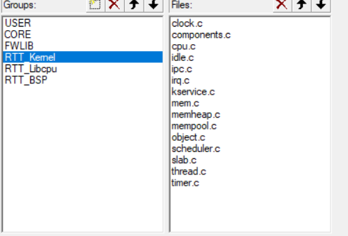
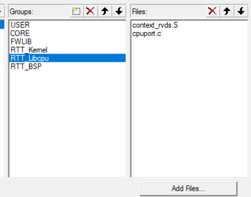
Add item grouping as follows

Add the following program files to the project respectively
 |
|
Add reference to header file
Error reporting solution
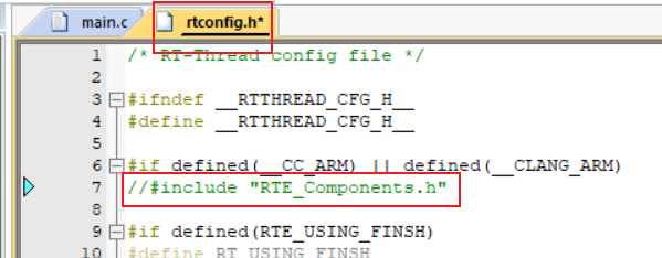
After the kernel migration is completed, an error occurs and the RTE is prompted_ Components. H header file not found

This file is useless and can be commented out directly
Comment out the above line of code and recompile, prompting us that the interrupted entry function is repeatedly defined
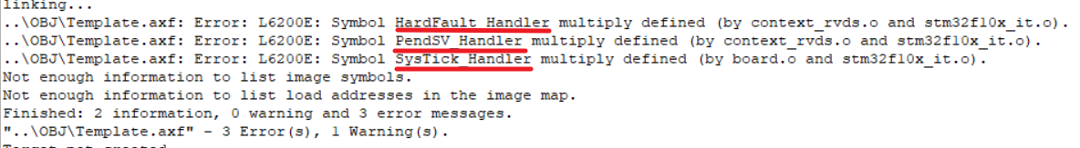
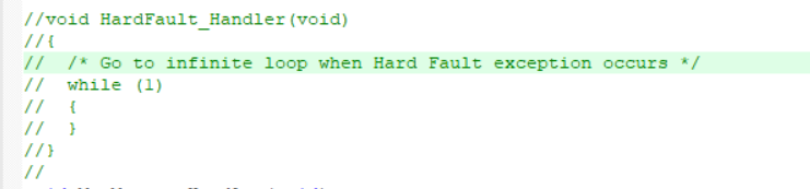
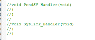
This is due to our RT_Thread Nano has helped us implement these three functions in the project, so we need to add stm32f10x_ it. The interrupt entry function in C program file is shielded
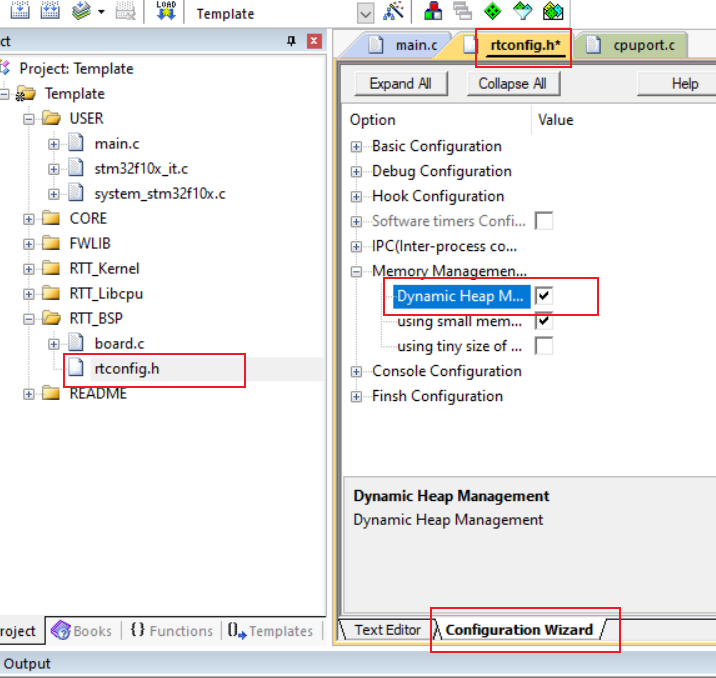
After recompilation, the system compiler may have a warning. Ignore it. Finally, modify the rtconfig file to enable dynamic memory heap management and complete kernel migration
Test Engineering
Use the following code to test the transplanted project
#include "stm32f10x.h"
#include <rtthread.h>

#ifndef RT_USING_HEAP 		// Determine whether to use dynamic memory heap
rt_err_t rst;
static struct rt_thread led_thread = {0};			//Create an LED thread
static rt_uint8_t led_thread_stack[256];			//LED for static thread_ Thread creates a stack space
#else
static rt_thread_t led_thread;
#endif
static void led_entry(void* parameter){
	while(1){
#ifndef RT_USING_HEAP
		/* The dynamic memory heap is not enabled, and the red light flashes */
		GPIO_WriteBit(GPIOA, GPIO_Pin_8, Bit_SET);
		rt_thread_mdelay(500);
		GPIO_WriteBit(GPIOA, GPIO_Pin_8, Bit_RESET);
		rt_thread_mdelay(500);
#else
		/* The dynamic memory heap is enabled and the yellow light flashes */
		GPIO_WriteBit(GPIOD, GPIO_Pin_2, Bit_SET);
		rt_thread_mdelay(500);
		GPIO_WriteBit(GPIOD, GPIO_Pin_2, Bit_RESET);
		rt_thread_mdelay(500);
#endif
	}
}
/* led Thread initialization and startup function */
static void LED_INIT(void){
	GPIO_InitTypeDef GPIO_InitStructure;
	RCC_APB2PeriphClockCmd(RCC_APB2Periph_GPIOA|RCC_APB2Periph_GPIOD, ENABLE);
	/*Initialize the GPIO corresponding to the two LED lights on the STM32 Mini development board*/
	GPIO_InitStructure.GPIO_Mode = GPIO_Mode_Out_PP;
	GPIO_InitStructure.GPIO_Speed = GPIO_Speed_50MHz;
	GPIO_InitStructure.GPIO_Pin = GPIO_Pin_2;				//green light
	GPIO_Init(GPIOD, &GPIO_InitStructure);
	GPIO_InitStructure.GPIO_Pin = GPIO_Pin_8;				//red light
	GPIO_Init(GPIOA, &GPIO_InitStructure);
	GPIO_SetBits(GPIOD, GPIO_Pin_2);								//Turn off the two LED lights
	GPIO_SetBits(GPIOA, GPIO_Pin_8);

#ifndef RT_USING_HEAP
	rst = rt_thread_init(	&led_thread,
									"led",
									led_entry, RT_NULL,
									&led_thread_stack[0], sizeof(led_thread_stack),
									RT_THREAD_PRIORITY_MAX-2, 20);
	if(rst == RT_EOK){
		rt_thread_startup(&led_thread);
	}
#else
	led_thread = rt_thread_create("led",
																led_entry, RT_NULL,
																256,
																RT_THREAD_PRIORITY_MAX-2, 20);
	if(led_thread != RT_NULL){
		rt_thread_startup(led_thread);			//Start led thread
	}
#endif
}

int main(void)
{
	LED_INIT();		//Start led thread
//	while(1){
//		/*Mask it, otherwise the led thread cannot be executed*/
//	}
}
Migrate console components (FISH)
Fish is a command-line component of RT thread, which provides a set of operation interfaces for users to call on the command line. It is mainly used to debug or view system information.
Serial port initialization
In main Add the following code to the C file
static int uart_init(void)
{
	GPIO_InitTypeDef GPIO_InitStructure;
	USART_InitTypeDef USART_InitStructure;
	USART_ClockInitTypeDef USART_ClockInitStructure;

	//-----------------------------------------------------
	RCC_APB2PeriphClockCmd(RCC_APB2Periph_GPIOA,ENABLE);
	RCC_APB2PeriphClockCmd(RCC_APB2Periph_USART1, ENABLE);

	USART_DeInit(USART1);


	//-----------------------------------------------------
	//Config USART1
	//TX(PA9)
	GPIO_InitStructure.GPIO_Pin = GPIO_Pin_9;
	GPIO_InitStructure.GPIO_Speed = GPIO_Speed_50MHz;
	GPIO_InitStructure.GPIO_Mode = GPIO_Mode_AF_PP;
	GPIO_Init(GPIOA, &GPIO_InitStructure);
	//Rx(PA10)
	GPIO_InitStructure.GPIO_Pin = GPIO_Pin_10;
	GPIO_InitStructure.GPIO_Speed = GPIO_Speed_50MHz;
	GPIO_InitStructure.GPIO_Mode = GPIO_Mode_IN_FLOATING;
	GPIO_Init(GPIOA, &GPIO_InitStructure);

	//-----------------------------------------------------
	//
	//USART_StructInit(&USART_InitStructure);
	USART_InitStructure.USART_BaudRate = 115200;
	USART_InitStructure.USART_WordLength = USART_WordLength_8b;
	USART_InitStructure.USART_StopBits = USART_StopBits_1;
	USART_InitStructure.USART_Parity = USART_Parity_No;
	USART_InitStructure.USART_HardwareFlowControl = USART_HardwareFlowControl_None;
	USART_InitStructure.USART_Mode = USART_Mode_Rx | USART_Mode_Tx;
	USART_Init(USART1, &USART_InitStructure);

	USART_ClockStructInit(&USART_ClockInitStructure);
	USART_ClockInitStructure.USART_Clock = USART_Clock_Disable;
	USART_ClockInitStructure.USART_CPOL = USART_CPOL_Low;
	USART_ClockInitStructure.USART_CPHA = USART_CPHA_2Edge;
	USART_ClockInitStructure.USART_LastBit = USART_LastBit_Disable;
	USART_ClockInit(USART1, &USART_ClockInitStructure);

	USART_GetFlagStatus(USART1, USART_FLAG_TC);
	USART_Cmd(USART1, ENABLE);

	return 0;
}
INIT_BOARD_EXPORT(uart_init);  /* Default initialization method 1: use the macro INIT_BOARD_EXPORT is automatically initialized */
Implement console output rt_hw_console_output
///*Transplant console to realize console output and docking rt_hw_console_output */
void rt_hw_console_output(const char *str)
{
    /* Enter critical zone */
    rt_enter_critical();

    while(*str!='\0')
    {
        if(*str=='\n')
        {
            USART_SendData(USART1,'\r');
            while(USART_GetFlagStatus(USART1, USART_FLAG_TXE)==RESET);
        }
        USART_SendData(USART1,*str++);
        while(USART_GetFlagStatus(USART1, USART_FLAG_TXE)==RESET);
    }

    /* Exit critical zone */
    rt_exit_critical();
}
In LED_ Add a printout statement to the thread entry function to test the program
rt_kprintf("Hello RT-Thread!!!\n");
Enable fish
In rtconfig Add the following macro definition to the H file
#define RTE_USING_FINSH // Start fish
When you start fish, you must start Dynamic memory heap .
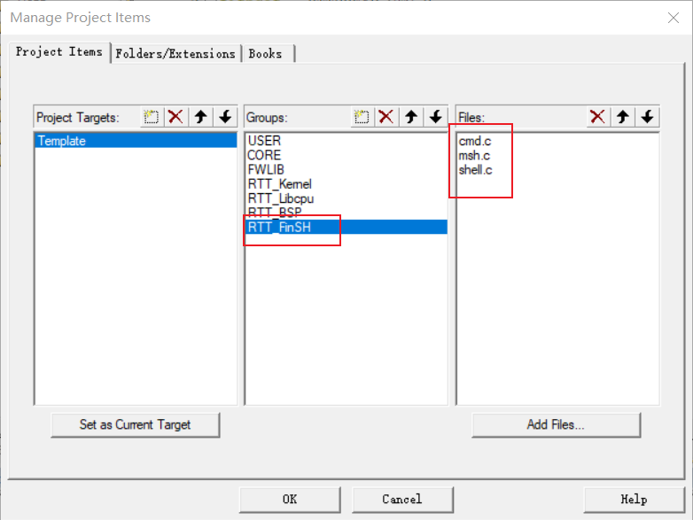
Add project groups and program files (in the components \ fish folder)
Add reference address of fish header file
Implement console command input rt_hw_console_getchar
/* To transplant fish and realize command-line interaction, you need to add fish source code, and then connect rt_hw_console_getchar */
/* Query mode */
char rt_hw_console_getchar(void)
{
    int ch = -1;

    if(USART_GetFlagStatus(USART1, USART_FLAG_RXNE) != RESET)
    {
        //USART_ClearITPendingBit(USART_DEBUG,  USART_FLAG_RXNE);
        ch = USART_ReceiveData(USART1) & 0xFF;
    }
    else
    {
        if(USART_GetFlagStatus(USART1, USART_FLAG_ORE) != RESET)
        {
            USART_ClearITPendingBit(USART1,  USART_FLAG_ORE);
        }
        rt_thread_mdelay(10);
    }

    return ch;
}
Error reporting solution
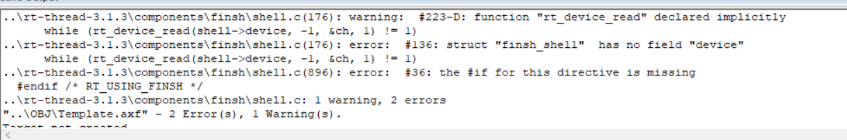
Locate the error position
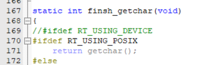
Cancel RT_ USING_ Comments defined by device macro, compiled
Test Engineering
#include "stm32f10x.h"
#include <rtthread.h>

#ifndef RT_USING_HEAP 		// Determine whether to use dynamic memory heap
rt_err_t rst;
static struct rt_thread led_thread = {0};			//Create an LED thread
static rt_uint8_t led_thread_stack[256];			//LED for static thread_ Thread creates a stack space
#else
static rt_thread_t led_thread;
#endif
static void led_entry(void* parameter){
#if defined(RTE_USING_FINSH) && defined(RT_USING_HEAP)
	static rt_uint8_t count;
	for(count=0; count<10; count++){
#else
	while(1){
#endif
#ifndef RT_USING_HEAP
		/* The dynamic memory heap is not enabled, and the red light flashes */
		GPIO_WriteBit(GPIOA, GPIO_Pin_8, Bit_RESET);
		rt_thread_mdelay(500);
		GPIO_WriteBit(GPIOA, GPIO_Pin_8, Bit_SET);
		rt_thread_mdelay(500);
#else
		/* The dynamic memory heap is enabled and the yellow light flashes */
		GPIO_WriteBit(GPIOD, GPIO_Pin_2, Bit_RESET);
		rt_thread_mdelay(500);
		GPIO_WriteBit(GPIOD, GPIO_Pin_2, Bit_SET);
		rt_thread_mdelay(500);
#endif
	}
	rt_kprintf("led_thread exit\n");
}
/* led Thread initialization and startup function */
static void LED_INIT(void){
	GPIO_InitTypeDef GPIO_InitStructure;
	RCC_APB2PeriphClockCmd(RCC_APB2Periph_GPIOA|RCC_APB2Periph_GPIOD, ENABLE);
	/*Initialize the GPIO corresponding to the two LED lights on the STM32 Mini development board*/
	GPIO_InitStructure.GPIO_Mode = GPIO_Mode_Out_PP;
	GPIO_InitStructure.GPIO_Speed = GPIO_Speed_50MHz;
	GPIO_InitStructure.GPIO_Pin = GPIO_Pin_2;				//green light
	GPIO_Init(GPIOD, &GPIO_InitStructure);
	GPIO_InitStructure.GPIO_Pin = GPIO_Pin_8;				//red light
	GPIO_Init(GPIOA, &GPIO_InitStructure);
	GPIO_SetBits(GPIOD, GPIO_Pin_2);								//Turn off the two LED lights
	GPIO_SetBits(GPIOA, GPIO_Pin_8);

#ifndef RT_USING_HEAP
	rst = rt_thread_init(	&led_thread,
									"led",
									led_entry, RT_NULL,
									&led_thread_stack[0], sizeof(led_thread_stack),
									RT_THREAD_PRIORITY_MAX-2, 20);
	if(rst == RT_EOK){
		rt_thread_startup(&led_thread);
	}
#else
	led_thread = rt_thread_create("led",
																led_entry, RT_NULL,
																256,
																RT_THREAD_PRIORITY_MAX-2, 20);
	if(led_thread != RT_NULL){
		rt_thread_startup(led_thread);			//Start led thread
	}
#endif
}
MSH_CMD_EXPORT(LED_INIT, "The LED test");
int main(void)
{
#ifndef RTE_USING_FINSH
	LED_INIT();
#endif
	while(1){
		/* Mask the while loop or suspend the thread, otherwise the led thread will not be executed */
		rt_thread_mdelay(500);
	}
}

#if defined(RTE_USING_FINSH)
/* Porting console to realize console output and docking rt_hw_console_output */
void rt_hw_console_output(const char *str)
{
    /* Enter critical zone */
    rt_enter_critical();

    while(*str!='\0')
    {
        if(*str=='\n')
        {
            USART_SendData(USART1,'\r');
            while(USART_GetFlagStatus(USART1, USART_FLAG_TXE)==RESET);
        }
        USART_SendData(USART1,*str++);
        while(USART_GetFlagStatus(USART1, USART_FLAG_TXE)==RESET);
    }

    /* Exit critical zone */
    rt_exit_critical();
}
/* To transplant fish and realize command-line interaction, you need to add fish source code, and then connect rt_hw_console_getchar */
/* Query mode */
char rt_hw_console_getchar(void)
{
    int ch = -1;

    if(USART_GetFlagStatus(USART1, USART_FLAG_RXNE) != RESET)
    {
        //USART_ClearITPendingBit(USART_DEBUG,  USART_FLAG_RXNE);
        ch = USART_ReceiveData(USART1) & 0xFF;
    }
    else
    {
        if(USART_GetFlagStatus(USART1, USART_FLAG_ORE) != RESET)
        {
            USART_ClearITPendingBit(USART1,  USART_FLAG_ORE);
        }
        rt_thread_mdelay(10);
    }

    return ch;
}

/* Serial port initialization */
static int uart_init(void)
{
	GPIO_InitTypeDef GPIO_InitStructure;
	USART_InitTypeDef USART_InitStructure;
	USART_ClockInitTypeDef USART_ClockInitStructure;

	//-----------------------------------------------------
	RCC_APB2PeriphClockCmd(RCC_APB2Periph_GPIOA,ENABLE);
	RCC_APB2PeriphClockCmd(RCC_APB2Periph_USART1, ENABLE);

	USART_DeInit(USART1);

	//-----------------------------------------------------
	//Config USART1
	//TX(PA9)
	GPIO_InitStructure.GPIO_Pin = GPIO_Pin_9;
	GPIO_InitStructure.GPIO_Speed = GPIO_Speed_50MHz;
	GPIO_InitStructure.GPIO_Mode = GPIO_Mode_AF_PP;
	GPIO_Init(GPIOA, &GPIO_InitStructure);
	//Rx(PA10)
	GPIO_InitStructure.GPIO_Pin = GPIO_Pin_10;
	GPIO_InitStructure.GPIO_Speed = GPIO_Speed_50MHz;
	GPIO_InitStructure.GPIO_Mode = GPIO_Mode_IN_FLOATING;
	GPIO_Init(GPIOA, &GPIO_InitStructure);

	//-----------------------------------------------------
	//
	//USART_StructInit(&USART_InitStructure);
	USART_InitStructure.USART_BaudRate = 115200;
	USART_InitStructure.USART_WordLength = USART_WordLength_8b;
	USART_InitStructure.USART_StopBits = USART_StopBits_1;
	USART_InitStructure.USART_Parity = USART_Parity_No;
	USART_InitStructure.USART_HardwareFlowControl = USART_HardwareFlowControl_None;
	USART_InitStructure.USART_Mode = USART_Mode_Rx | USART_Mode_Tx;
	USART_Init(USART1, &USART_InitStructure);

	USART_ClockStructInit(&USART_ClockInitStructure);
	USART_ClockInitStructure.USART_Clock = USART_Clock_Disable;
	USART_ClockInitStructure.USART_CPOL = USART_CPOL_Low;
	USART_ClockInitStructure.USART_CPHA = USART_CPHA_2Edge;
	USART_ClockInitStructure.USART_LastBit = USART_LastBit_Disable;
	USART_ClockInit(USART1, &USART_ClockInitStructure);

	USART_GetFlagStatus(USART1, USART_FLAG_TC);
	USART_Cmd(USART1, ENABLE);

	return 0;
}
INIT_BOARD_EXPORT(uart_init);  /* The default option is initialization method 1: use the macro INIT_BOARD_EXPORT is automatically initialized */
#endif /* RTE_USING_FINSH */
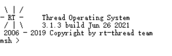
After the project is downloaded, open the serial assistant and reset the development board. If the migration is successful, the version information and msh command input prompt will be printed
Input LED_ The green LED on the init instruction development board will flash ten times, and the console will print the LED after completion_ thread exit
Use the RT thread nano package provided by MDK for transplantation
RT thread nano package download
Method 1: RT thread offline installation package
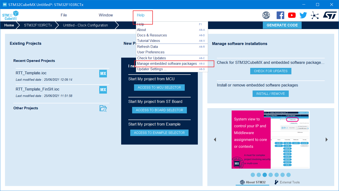
Method 2:
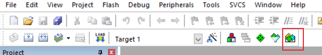
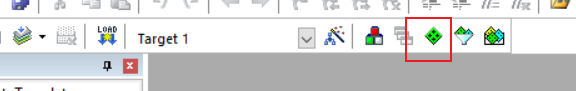
Open the MDK software and click the Pack Installer icon in the toolbar
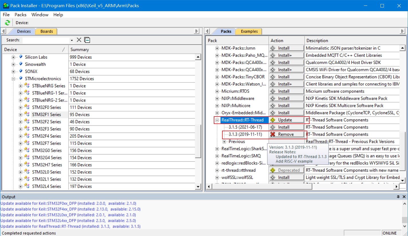
Click the Pack on the right, expand Generic, find realthread:: RT thread, and select version 3.1.3 for installation
Project creation
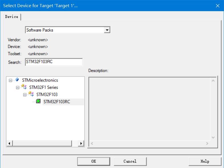
Create an STM32F103RC project
After creating the project, click manage run time environment
Check the following options
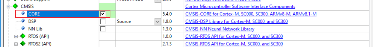
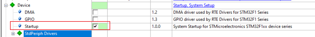
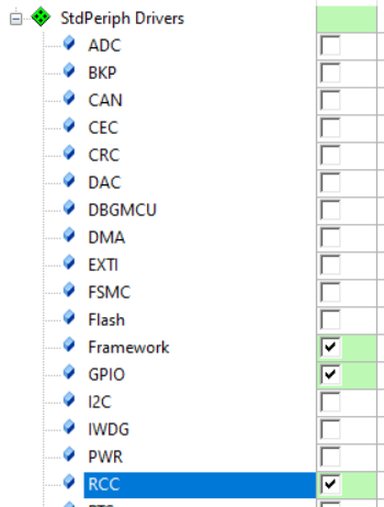
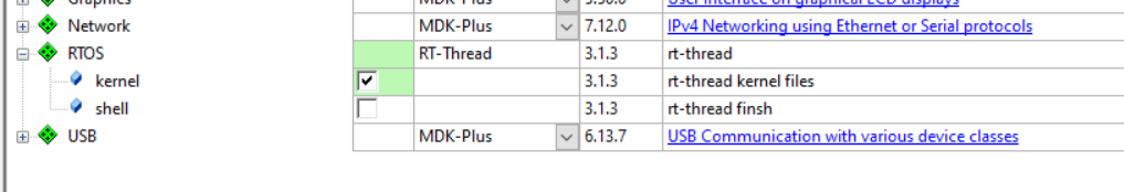
Click OK after checking all items. There will be a warning after compiling the project. Ignore it and complete the transplantation of RT thread nano kernel.
Test Engineering
Use the previous code pair engineering If everything runs normally, it means that the migration is successful.
Add fish component
Open the MDK software, click the Pack Installer icon on the toolbar, check the following parameters and click OK to complete the installation of components.
When using the fish component, be sure to enable the dynamic memory heap

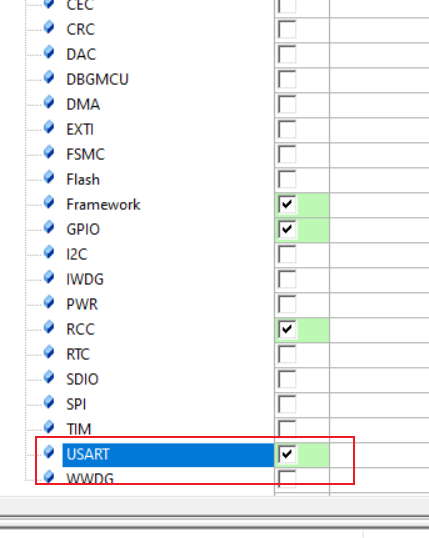
Realize serial port initialization and console input and output functions
specific engineering
RT thread nano 3.1.5 migration using CubeMX
- Download Cube MX 5.0 at https://www.st.com/en/development-tools/stm32cubemx.html .
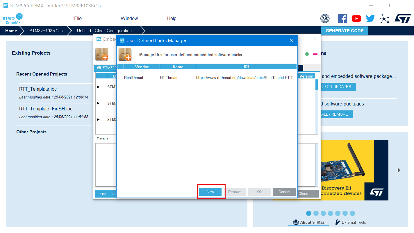
- Download the RT thread nano pack installation package on CubeMX.
Get RT thread nano package
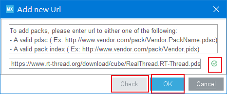
Add in CubeMX https://www.rt-thread.org/download/cube/RealThread.RT-Thread.pdsc .
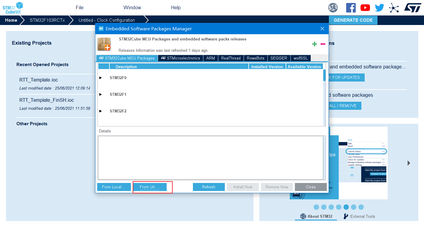
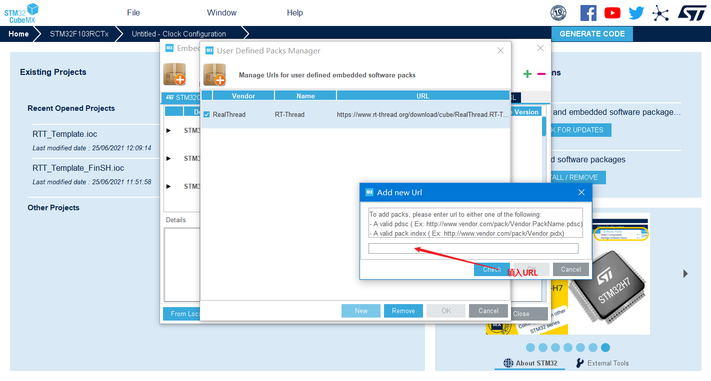
Click Check. After passing the check, click OK to finish adding the kernel
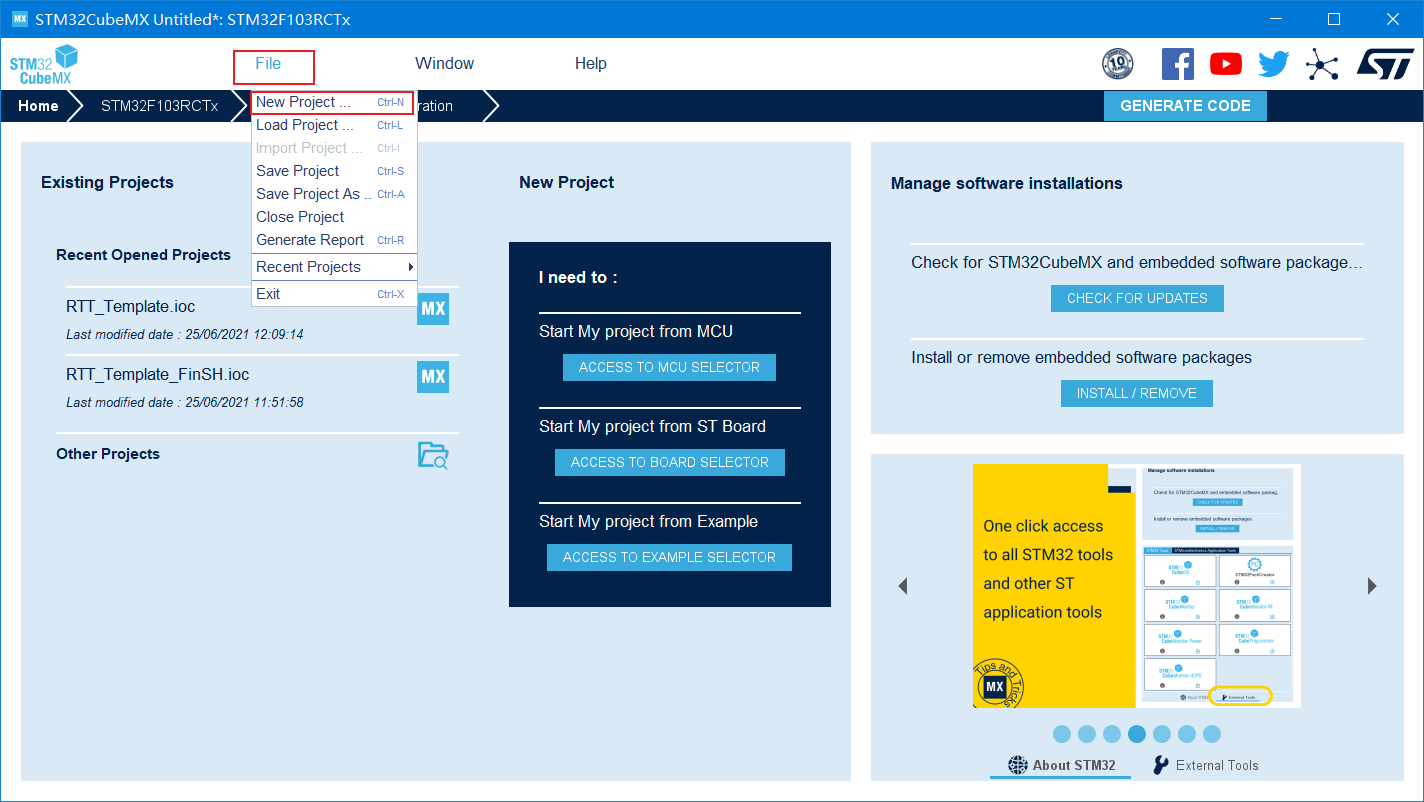
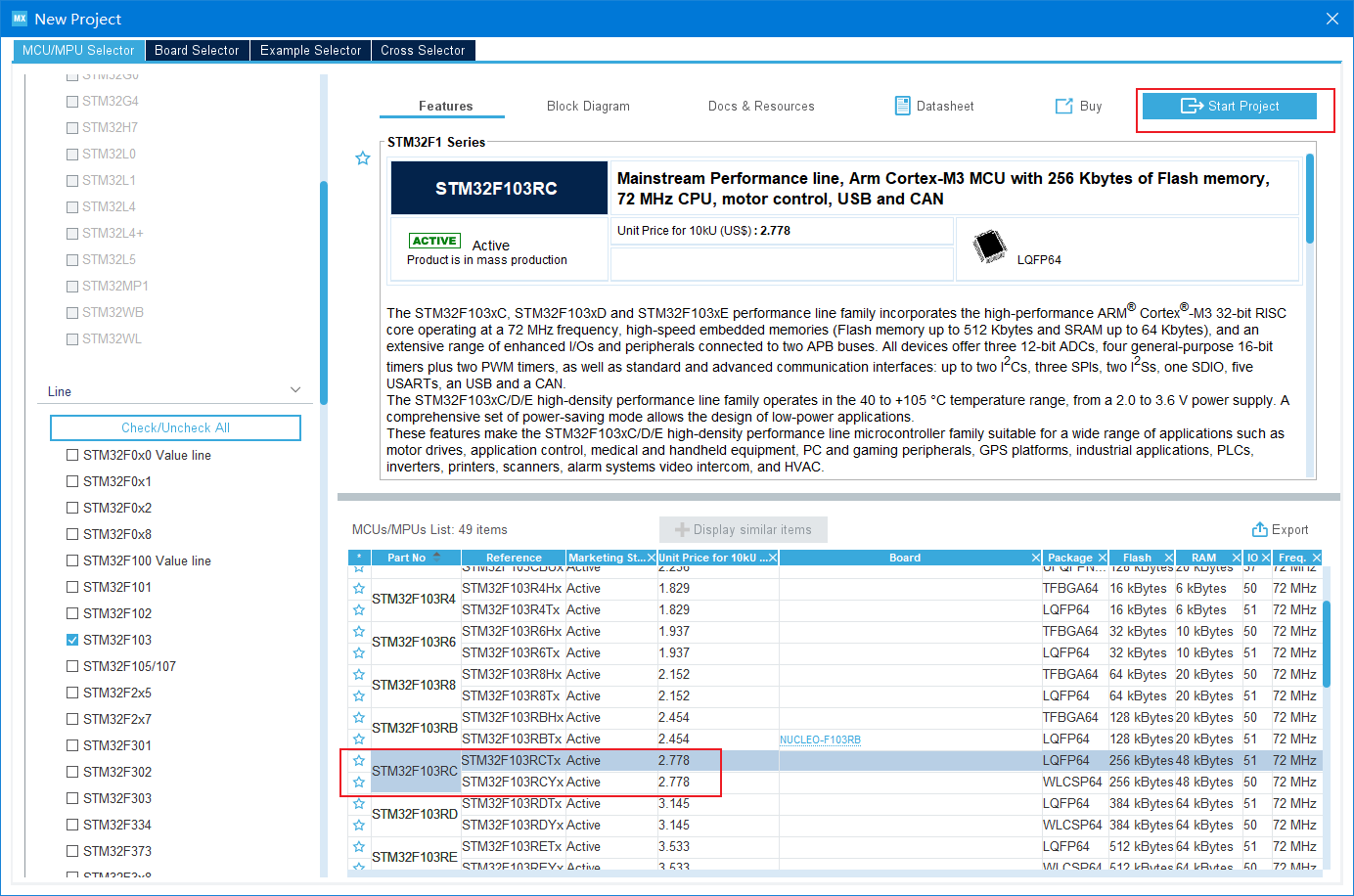
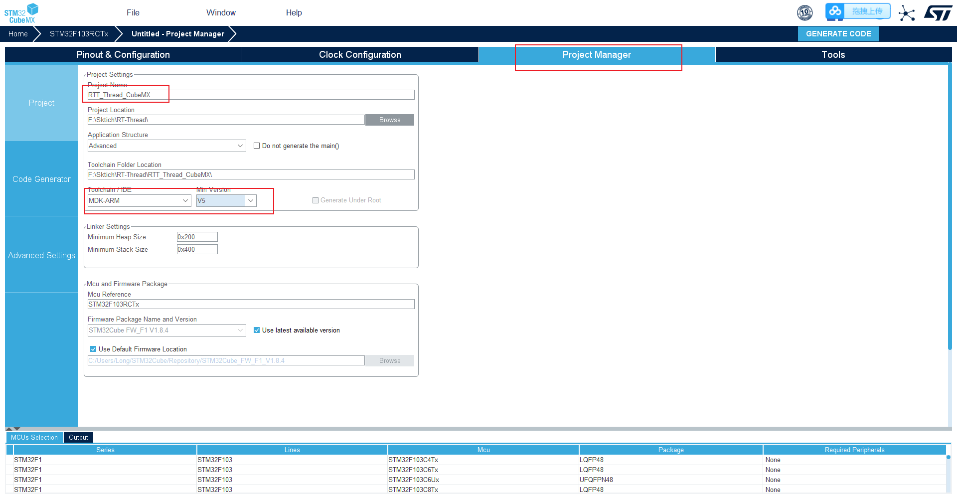
Create project
Select the chip model STM32F103RC
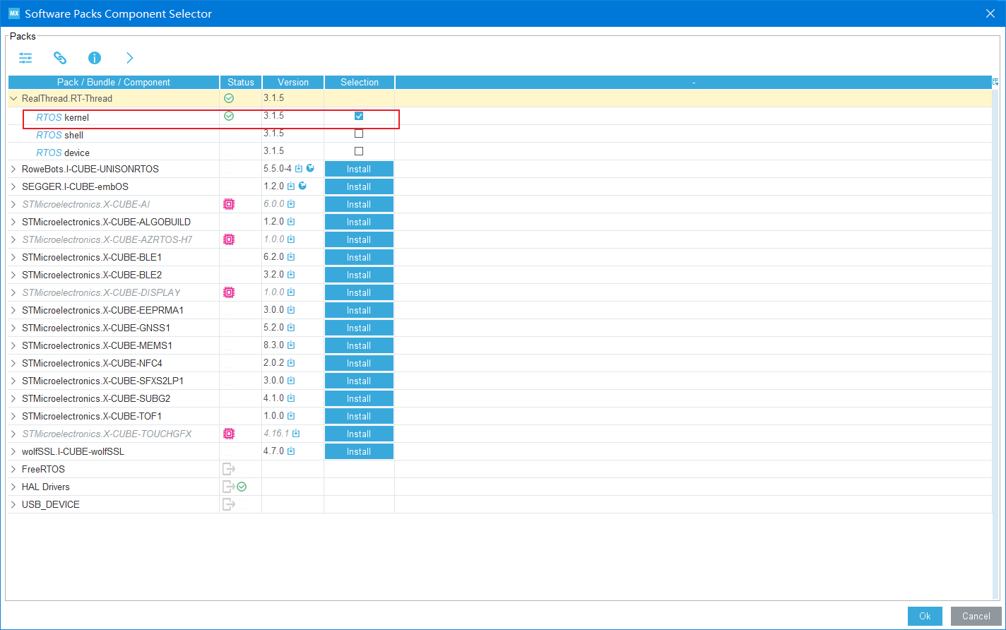
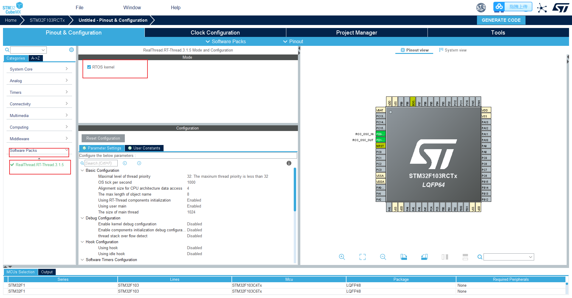
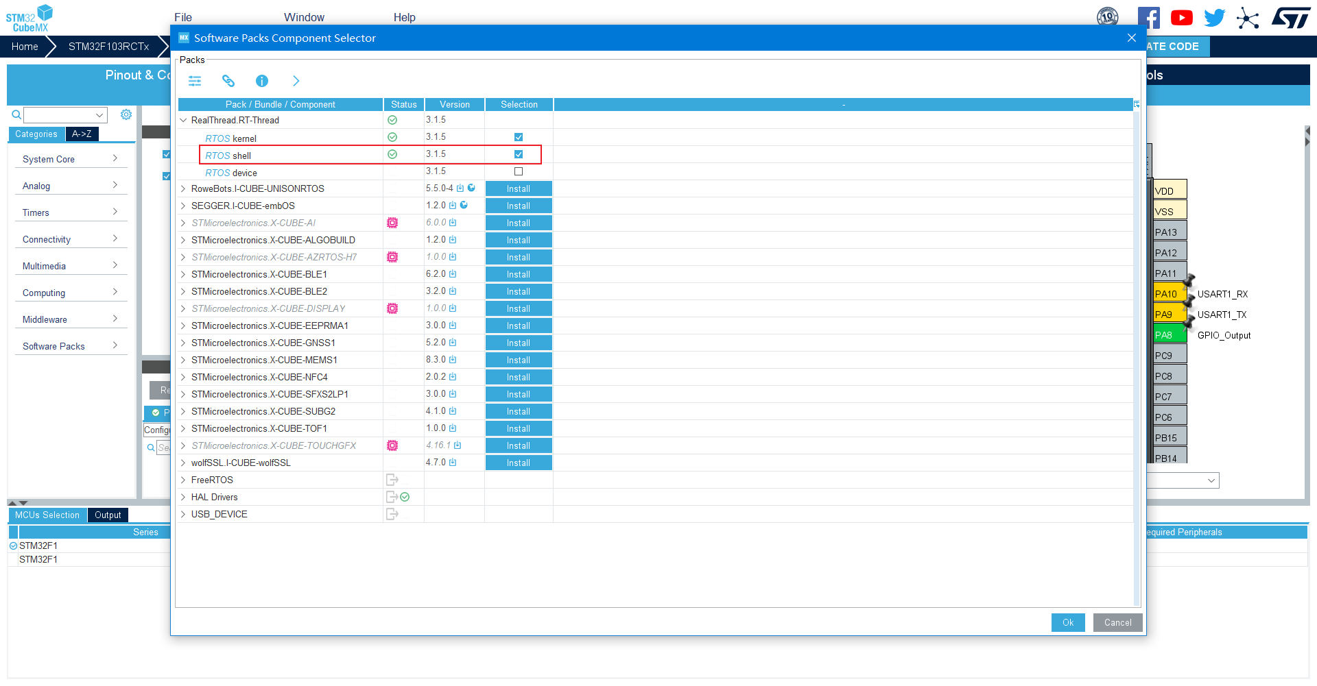
Select RT thread nano package
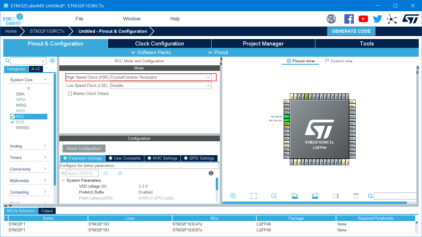
Choose to use an external crystal oscillator as the clock source
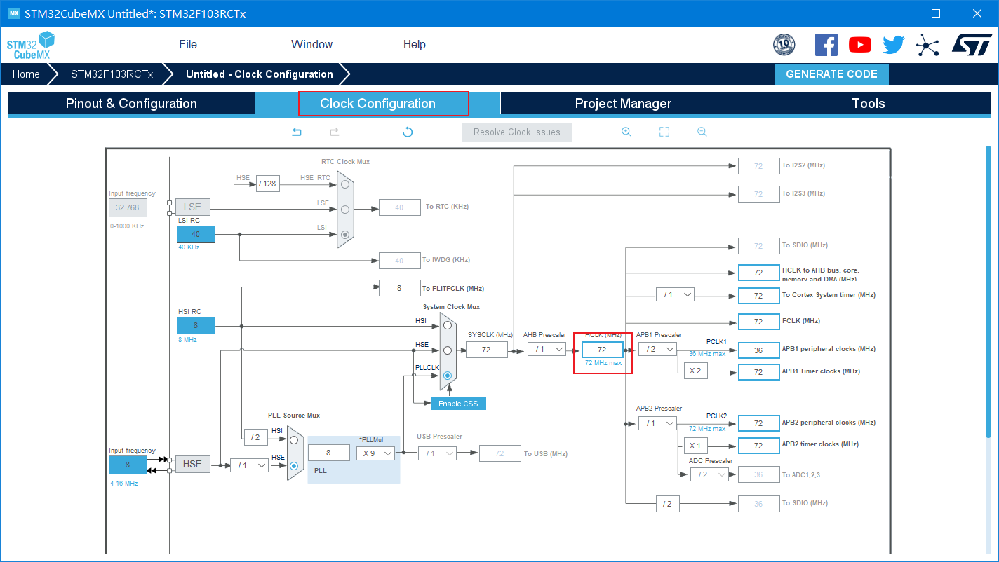
Set HCLK to 72MHz
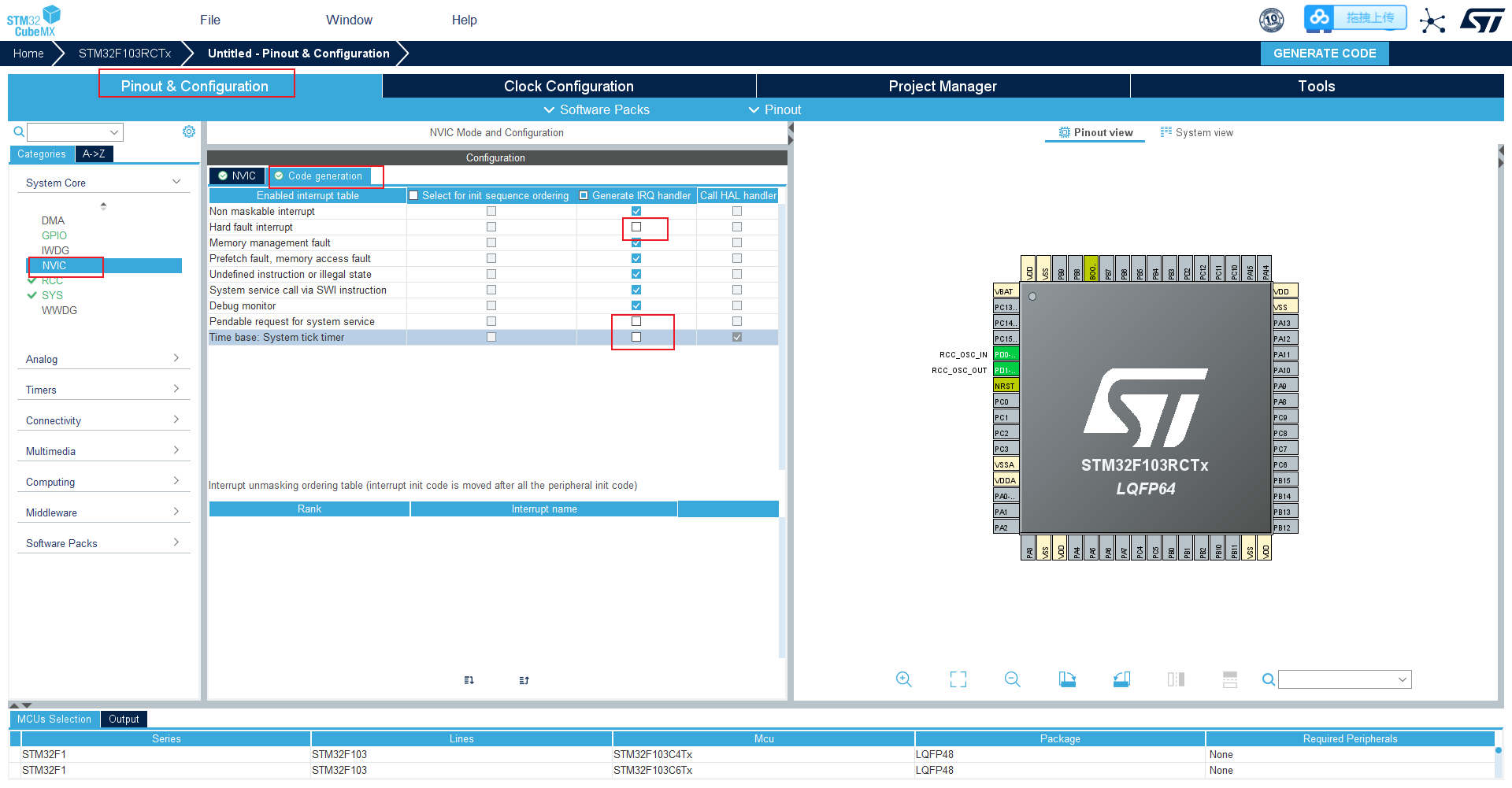
Set interrupt
Select Nano component
Do not enable console
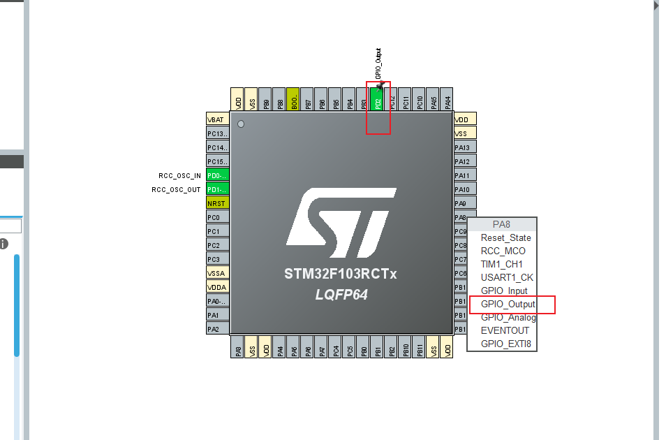
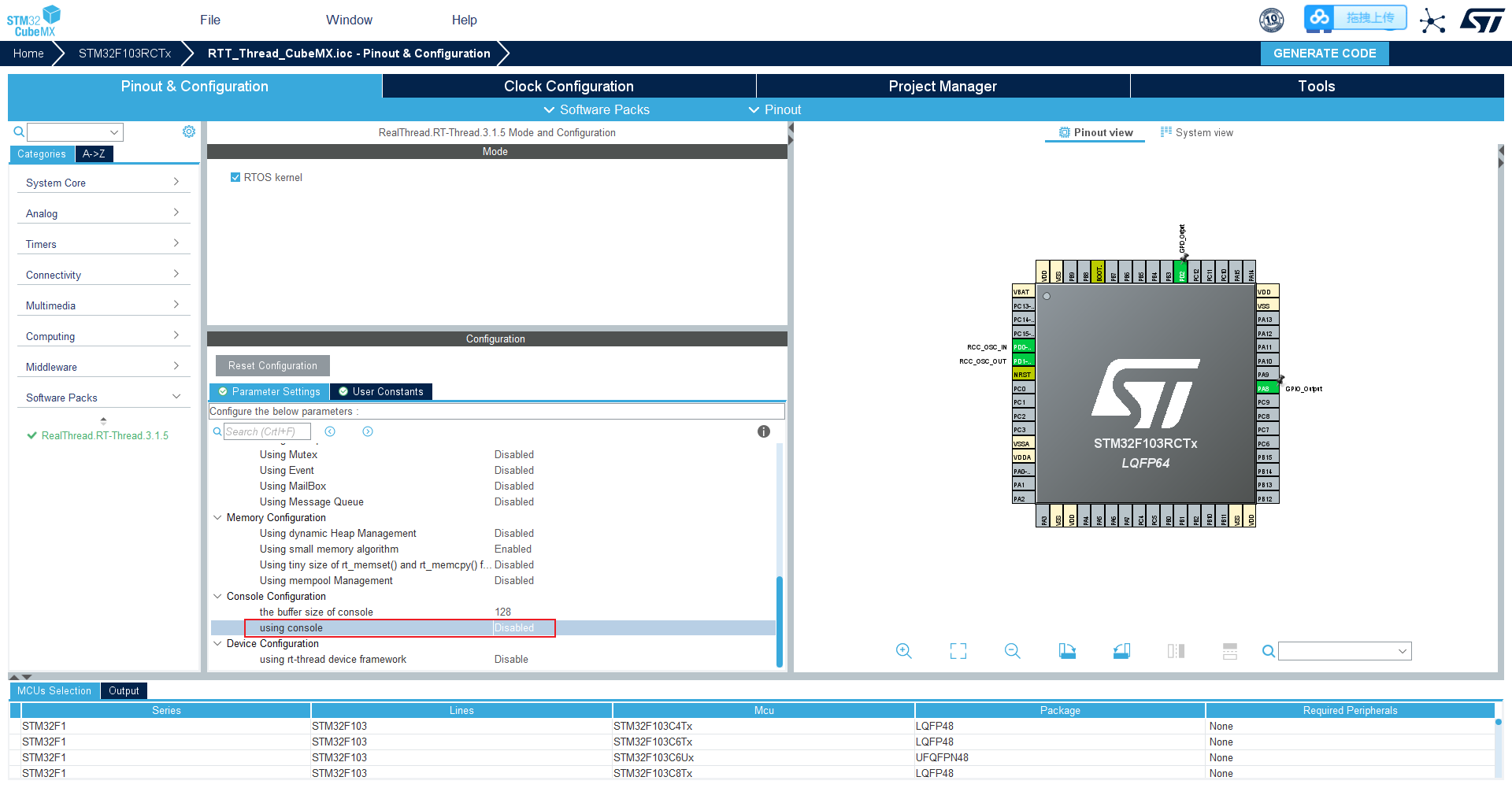 Set the pin corresponding to the LED of the development board to OUTPUT
Enter the project name and select the software and version to use
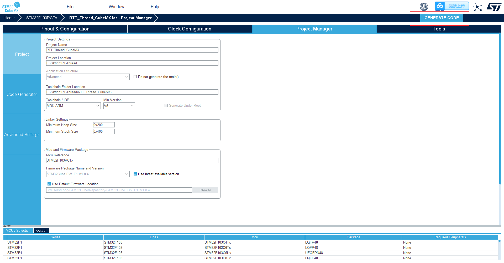
Create project (ignore warning)
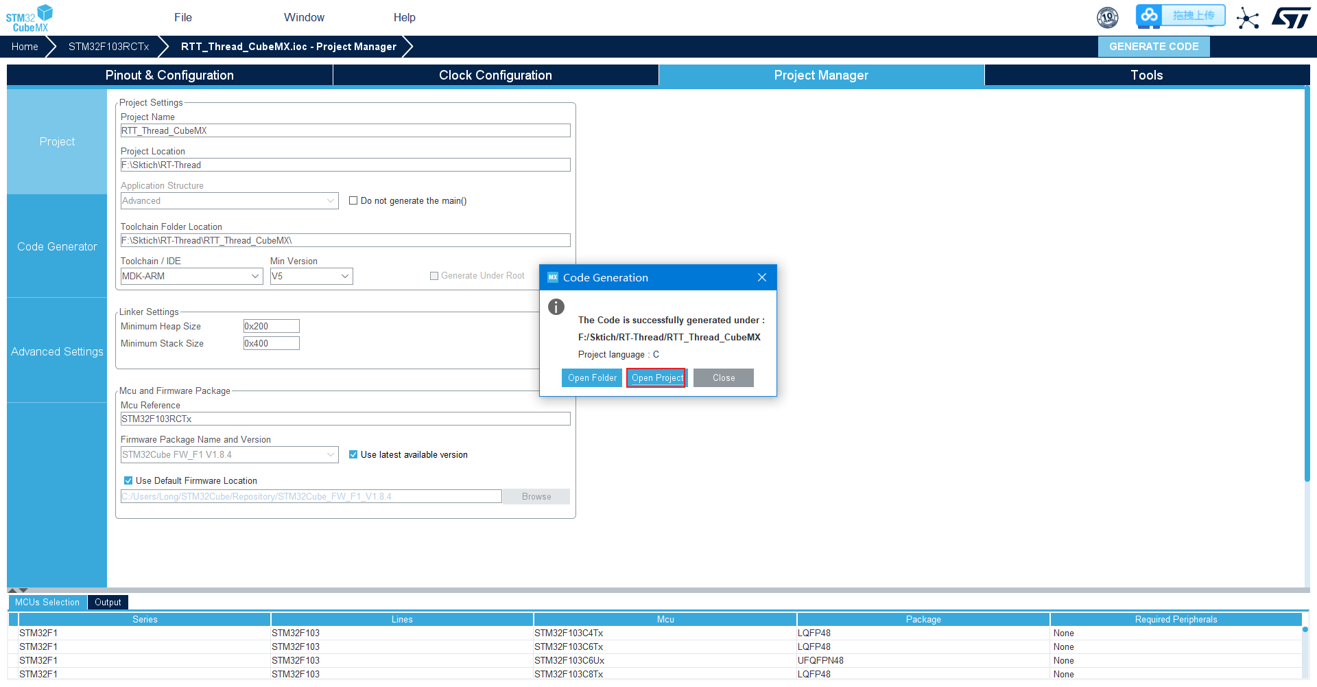
Open project
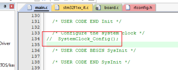
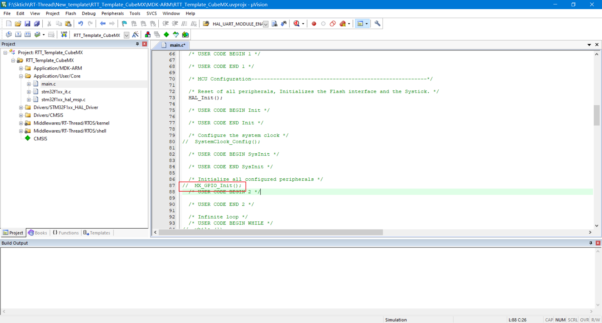
Shield SystemClock_Config() function, which is in board C has been called
Test Engineering
Migrate fish
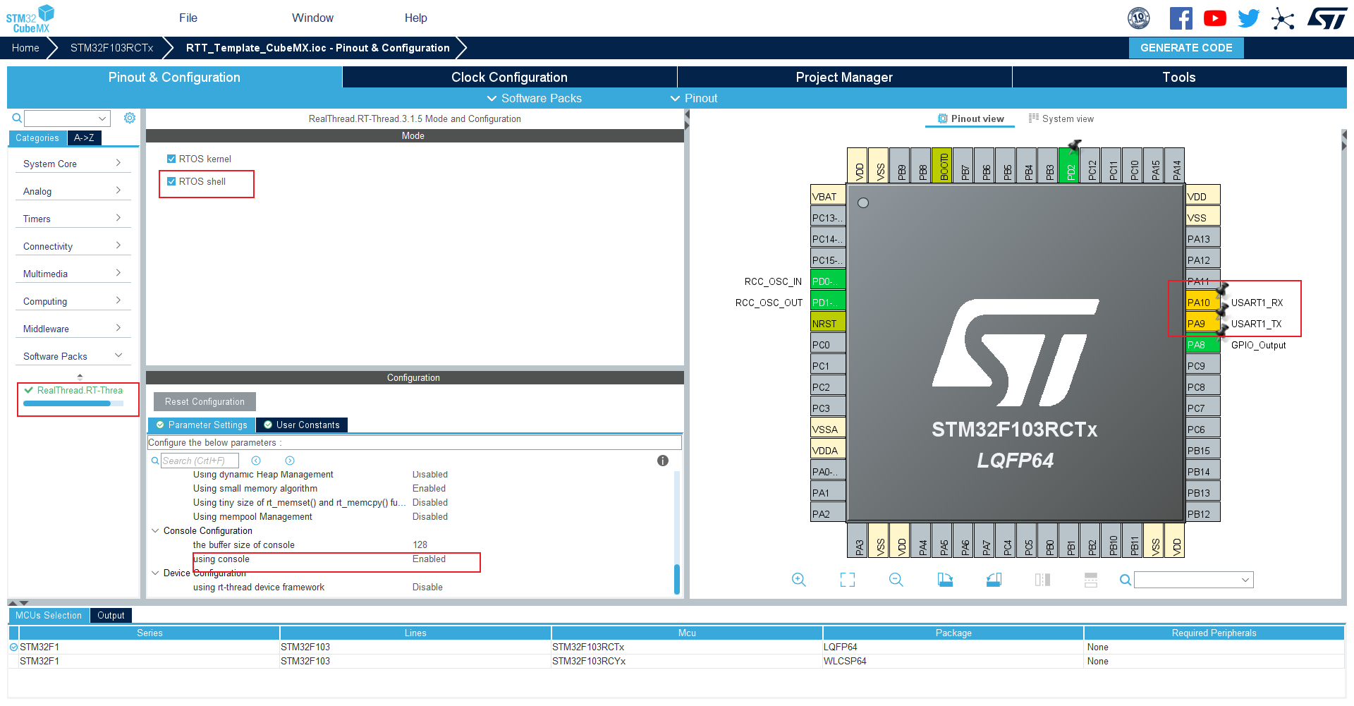
Select package
Select Nano component and set the function of serial port 1 pin
Initialization function of masked GPIO
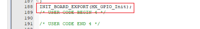
Add GPIO initialization function to board level initialization
INIT_BOARD_EXPORT(MX_GPIO_Init);
Configure rtconfig H file
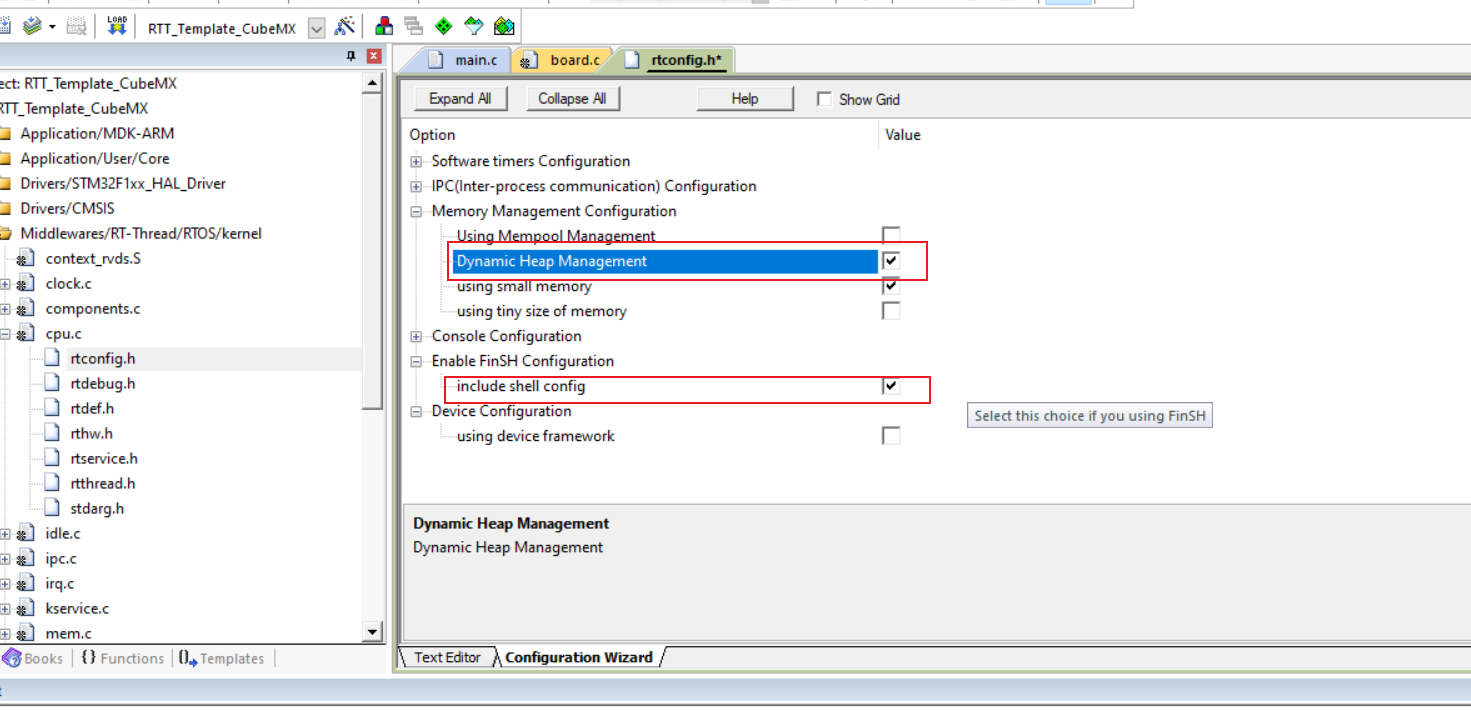
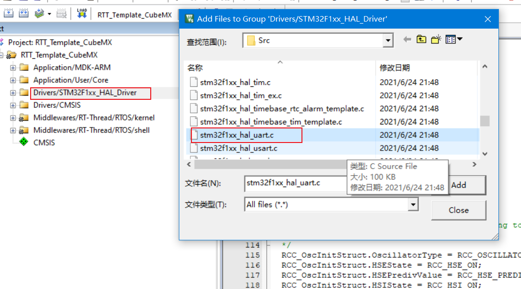
Add HAL library file of serial port
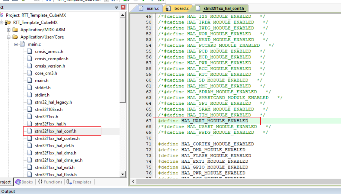
Enable serial port clock

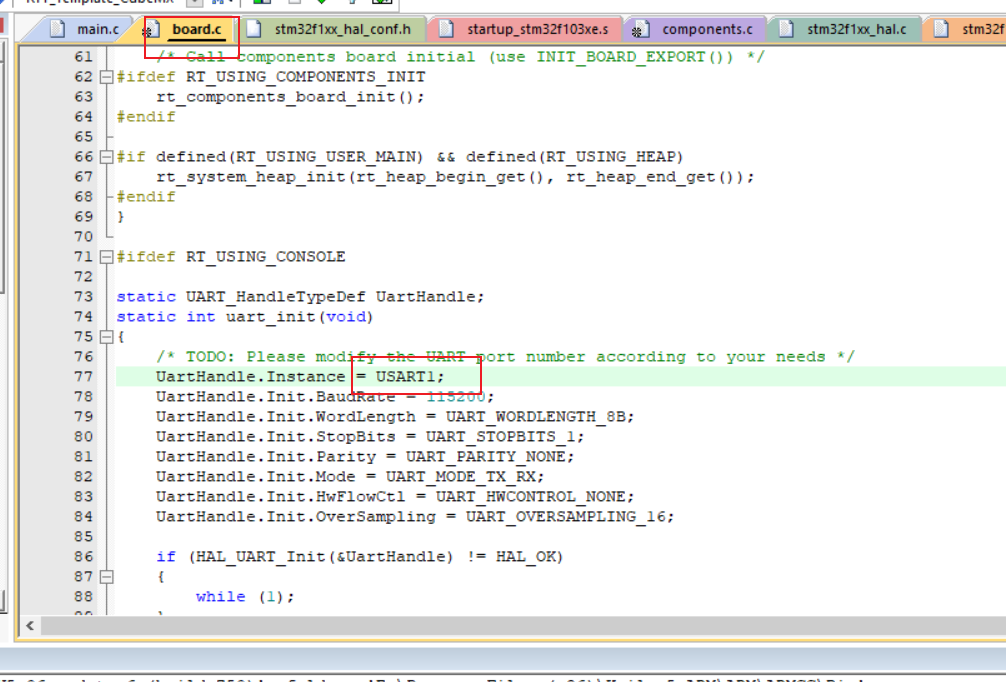
Modify the serial port to USART1
After all changes are completed, compile, download and migrate
Test Engineering
/* USER CODE BEGIN Header */
/**
******************************************************************************
* @file : main.c
* @brief : Main program body
******************************************************************************
* @attention
*
* <h2><center>© Copyright (c) 2021 STMicroelectronics.
* All rights reserved.</center></h2>
*
* This software component is licensed by ST under Ultimate Liberty license
* SLA0044, the "License"; You may not use this file except in compliance with
* the License. You may obtain a copy of the License at:
* www.st.com/SLA0044
*
******************************************************************************
*/
/* USER CODE END Header */
/* Includes ------------------------------------------------------------------*/
#include "main.h"
#include <rtthread.h>
/* Private includes ----------------------------------------------------------*/
/* USER CODE BEGIN Includes */
/* USER CODE END Includes */
/* Private typedef -----------------------------------------------------------*/
/* USER CODE BEGIN PTD */
/* USER CODE END PTD */
/* Private define ------------------------------------------------------------*/
/* USER CODE BEGIN PD */
/* USER CODE END PD */
/* Private macro -------------------------------------------------------------*/
/* USER CODE BEGIN PM */
/* USER CODE END PM */
/* Private variables ---------------------------------------------------------*/
/* USER CODE BEGIN PV */
#ifndef RT_USING_HEAP // Determine whether to use dynamic memory heap
rt_err_t rst;
static struct rt_thread led_thread = {0}; //Create an LED thread
static rt_uint8_t led_thread_stack[256]; //LED for static thread_ Thread creates a stack space
#else
static rt_thread_t led_thread;
#endif
/* USER CODE END PV */
/* Private function prototypes -----------------------------------------------*/
void SystemClock_Config(void);
static int MX_GPIO_Init(void);
/* USER CODE BEGIN PFP */
/* USER CODE END PFP */
/* Private user code ---------------------------------------------------------*/
/* USER CODE BEGIN 0 */
static void led_entry(void* parameter){
#if defined(RT_USING_FINSH) && defined(RT_USING_HEAP)
static rt_uint8_t count;
for(count=0; count<10; count++){
#else
while(1){
#endif
#ifndef RT_USING_HEAP
/* The dynamic memory heap is not enabled, and the red light flashes */
HAL_GPIO_WritePin(GPIOA, GPIO_PIN_8, GPIO_PIN_RESET);
rt_thread_mdelay(500);
HAL_GPIO_WritePin(GPIOA, GPIO_PIN_8, GPIO_PIN_SET);
rt_thread_mdelay(500);
#else
/* The dynamic memory heap is enabled and the yellow light flashes */
HAL_GPIO_WritePin(GPIOD, GPIO_PIN_2, GPIO_PIN_RESET);
rt_thread_mdelay(500);
HAL_GPIO_WritePin(GPIOD, GPIO_PIN_2, GPIO_PIN_SET);
rt_thread_mdelay(500);
#endif
}
rt_kprintf("led_thread exit\n");
}
/* led Thread initialization and startup function */
static void LED_INIT(void){
#ifndef RT_USING_HEAP
rst = rt_thread_init( &led_thread,
"led",
led_entry, RT_NULL,
&led_thread_stack[0], sizeof(led_thread_stack),
RT_THREAD_PRIORITY_MAX-2, 20);
if(rst == RT_EOK){
rt_thread_startup(&led_thread);
}
#else
led_thread = rt_thread_create("led",
led_entry, RT_NULL,
256,
RT_THREAD_PRIORITY_MAX-2, 20);
if(led_thread != RT_NULL){
rt_thread_startup(led_thread); //Start led thread
}
#endif
}
MSH_CMD_EXPORT(LED_INIT, "The LED test");
/* USER CODE END 0 */
/**
* @brief The application entry point.
* @retval int
*/
int main(void)
{
/* USER CODE BEGIN 1 */
/* USER CODE END 1 */
/* MCU Configuration--------------------------------------------------------*/
/* Reset of all peripherals, Initializes the Flash interface and the Systick. */
HAL_Init();
/* USER CODE BEGIN Init */
/* USER CODE END Init */
/* Configure the system clock */
// SystemClock_Config();
/* USER CODE BEGIN SysInit */
/* USER CODE END SysInit */
/* Initialize all configured peripherals */
// MX_GPIO_Init();
/* USER CODE BEGIN 2 */
#ifndef RT_USING_FINSH
LED_INIT();
#endif
/* USER CODE END 2 */
/* Infinite loop */
/* USER CODE BEGIN WHILE */
while (1)
{
/* USER CODE END WHILE */
rt_thread_mdelay(500); //Suspend the main thread so that other threads can execute
/* USER CODE BEGIN 3 */
}
/* USER CODE END 3 */
}
/**
* @brief System Clock Configuration
* @retval None
*/
void SystemClock_Config(void)
{
RCC_OscInitTypeDef RCC_OscInitStruct = {0};
RCC_ClkInitTypeDef RCC_ClkInitStruct = {0};
/** Initializes the RCC Oscillators according to the specified parameters
* in the RCC_OscInitTypeDef structure.
*/
RCC_OscInitStruct.OscillatorType = RCC_OSCILLATORTYPE_HSE;
RCC_OscInitStruct.HSEState = RCC_HSE_ON;
RCC_OscInitStruct.HSEPredivValue = RCC_HSE_PREDIV_DIV1;
RCC_OscInitStruct.HSIState = RCC_HSI_ON;
RCC_OscInitStruct.PLL.PLLState = RCC_PLL_ON;
RCC_OscInitStruct.PLL.PLLSource = RCC_PLLSOURCE_HSE;
RCC_OscInitStruct.PLL.PLLMUL = RCC_PLL_MUL9;
if (HAL_RCC_OscConfig(&RCC_OscInitStruct) != HAL_OK)
{
Error_Handler();
}
/** Initializes the CPU, AHB and APB buses clocks
*/
RCC_ClkInitStruct.ClockType = RCC_CLOCKTYPE_HCLK|RCC_CLOCKTYPE_SYSCLK
|RCC_CLOCKTYPE_PCLK1|RCC_CLOCKTYPE_PCLK2;
RCC_ClkInitStruct.SYSCLKSource = RCC_SYSCLKSOURCE_PLLCLK;
RCC_ClkInitStruct.AHBCLKDivider = RCC_SYSCLK_DIV1;
RCC_ClkInitStruct.APB1CLKDivider = RCC_HCLK_DIV2;
RCC_ClkInitStruct.APB2CLKDivider = RCC_HCLK_DIV1;
if (HAL_RCC_ClockConfig(&RCC_ClkInitStruct, FLASH_LATENCY_2) != HAL_OK)
{
Error_Handler();
}
}
/**
* @brief GPIO Initialization Function
* @param None
* @retval None
*/
static int MX_GPIO_Init(void)
{
GPIO_InitTypeDef GPIO_InitStruct = {0};
/* GPIO Ports Clock Enable */
__HAL_RCC_GPIOD_CLK_ENABLE();
__HAL_RCC_GPIOA_CLK_ENABLE();
__HAL_RCC_USART1_CLK_ENABLE();
/*Configure GPIO pin Output Level */
HAL_GPIO_WritePin(GPIOA, GPIO_PIN_8, GPIO_PIN_RESET);
/*Configure GPIO pin Output Level */
HAL_GPIO_WritePin(GPIOD, GPIO_PIN_2, GPIO_PIN_RESET);
/*Configure GPIO pin : PA8 */
GPIO_InitStruct.Pin = GPIO_PIN_8;
GPIO_InitStruct.Mode = GPIO_MODE_OUTPUT_PP;
GPIO_InitStruct.Pull = GPIO_NOPULL;
GPIO_InitStruct.Speed = GPIO_SPEED_FREQ_LOW;
HAL_GPIO_Init(GPIOA, &GPIO_InitStruct);
/*Configure GPIO pin : PA9 */
GPIO_InitStruct.Pin = GPIO_PIN_9;
GPIO_InitStruct.Mode = GPIO_MODE_AF_PP;
GPIO_InitStruct.Speed = GPIO_SPEED_FREQ_HIGH;
HAL_GPIO_Init(GPIOA, &GPIO_InitStruct);
/*Configure GPIO pin : PA10 */
GPIO_InitStruct.Pin = GPIO_PIN_10;
GPIO_InitStruct.Mode = GPIO_MODE_INPUT;
GPIO_InitStruct.Pull = GPIO_NOPULL;
HAL_GPIO_Init(GPIOA, &GPIO_InitStruct);
/*Configure GPIO pin : PD2 */
GPIO_InitStruct.Pin = GPIO_PIN_2;
GPIO_InitStruct.Mode = GPIO_MODE_OUTPUT_PP;
GPIO_InitStruct.Pull = GPIO_NOPULL;
GPIO_InitStruct.Speed = GPIO_SPEED_FREQ_LOW;
HAL_GPIO_Init(GPIOD, &GPIO_InitStruct);
return 0;
}
INIT_BOARD_EXPORT(MX_GPIO_Init);
/* USER CODE BEGIN 4 */
/* USER CODE END 4 */
/**
* @brief This function is executed in case of error occurrence.
* @retval None
*/
void Error_Handler(void)
{
/* USER CODE BEGIN Error_Handler_Debug */
/* User can add his own implementation to report the HAL error return state */
__disable_irq();
while (1)
{
}
/* USER CODE END Error_Handler_Debug */
}
#ifdef USE_FULL_ASSERT
/**
* @brief Reports the name of the source file and the source line number
* where the assert_param error has occurred.
* @param file: pointer to the source file name
* @param line: assert_param error line source number
* @retval None
*/
void assert_failed(uint8_t *file, uint32_t line)
{
/* USER CODE BEGIN 6 */
/* User can add his own implementation to report the file name and line number,
ex: printf("Wrong parameters value: file %s on line %d\r\n", file, line) */
/* USER CODE END 6 */
}
#endif /* USE_FULL_ASSERT */
/************************ (C) COPYRIGHT STMicroelectronics *****END OF FILE****/
Article reference
https://blog.csdn.net/killercode11/article/details/104290949
https://www.rt-thread.org/document/site/#/rt-thread-version/rt-thread-nano/an0038-nano-introduction
Article code download address
https://gitee.com/SLHU/rt_-thread_-project