This article will introduce the theory and practical application of I2C communication mode from theory to practice. The theory part mainly describes the physical structure of I2C bus, the relevant provisions in its protocol and several different communication processes. In the practice part, we will take a display module commonly used in various development occasions - 4-wire 0.96 inch OLED display screen and MS5837 pressure sensor used in my ongoing Dachuang project as an example to introduce how to drive the module with I2C protocol on STM32F407. This is my first blog post (just a mediocre college student who has just started embedded) in CSDN, which aims to summarize relevant knowledge. If there are mistakes, you are welcome to criticize and correct! I VX: Cyy15880234628. It would be great if you could help others!
1, I2C related knowledge
1. Physical layer
(1) Definition
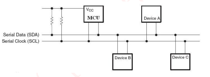
IIC is the abbreviation of inter integrated circuit, that is, two-wire serial bus. It has a serial bus composed of data line SDA and clock line SCL, which can send and receive data. The bus structure is shown in the figure:
(2) Communication mode
According to the definition, there is only one data line, so I2C communication adopts half duplex communication, that is, data can be transmitted in two directions on the data line, but can not be transmitted and received at the same time. (it can be imagined as a water pipe. Water can flow from the left end to the right end or from the right end to the left end, but it can't flow from left to right and from right to left at the same time. You can't have both!)
2. Protocol layer
In the protocol layer, we first understand the relevant provisions corresponding to several terms used in the communication process.
(I only know so much, hahaha, after all, I2C protocol can't be read in one day or two.)
(1) Idle state
SDA and SCL signal lines are at high level at the same time, and the specified bus is in idle state at this time.
(2) Definition of start signal and stop signal
Start signal: SCL is at high level, and SDA jumps from high level to low level;
Stop signal: when SCL is high level, SDA jumps from low level to high level.
Just looking at the text explanation seems very abstract. Come on, let's go directly to the above picture (the ugly picture I drew myself)!
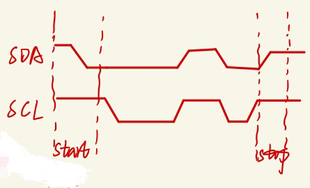
In fact, the start signal is represented by the start signal, which is different from the stop signal defined by SCL. (of course, my understanding of these two regulations is that SDA can be imagined as a knife of a switch. Down, that is, close, and start transmission; up, that is, disconnect, and stop transmission.)
(3) Response signal
The transmitter generates a byte, releases the bus during the ninth clock pulse, and the receiver feeds back a reply signal. The response signal can be divided into two types: ① effective response (ACK): the response signal is low level; ② Invalid response (NACK): the response signal is high level.
(4) Data transmission
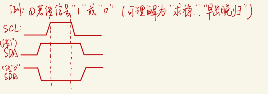
Each data has a clock pulse for synchronous control, that is, with the cooperation of SCL serial clock, SDA transmits each bit of data bit by bit, and the transmission starts from the edge.
(5) Data validity
What kind of data is effective in the transmission process? During the high level of the clock signal, the data on the data line remains stable. (maybe it's hard to understand, then go to the figure above!)
3. I2C basic reading and writing process
It mainly includes three communication processes: the host writes data to the slave, the host reads the slave data, and composite communication (both read and write). In the application, the first two communication processes are mainly used, and composite communication is rare. Here I will only introduce the first two, and the driving actual combat part will also show these two with examples.
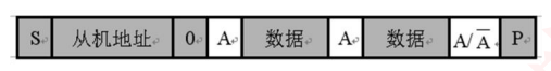
(1) The master writes data to the slave
The communication process is shown in the figure below:

(the shaded part indicates that the data is transmitted from the master to the slave, and the unshaded part indicates that the data is transmitted from the slave to the master. A indicates response, and a non indicates non response (high level). S represents the start signal and P represents the end signal.)
First, the host generates a start signal and starts transmitting data. Then, the host sends the address bit and read-write bit (0) to the slave to determine which slave wants to receive the data sent by the host. Then it starts to send valid data from the host to the slave, and the slave returns valid response or invalid response according to the received data. Finally, the host generates a stop signal to indicate the end of the transmission.
The whole process is like this. I don't know whether I can express it clearly. In fact, we can also compare the process of sending express. We should know who to send to and what to send. We should give a feedback when signing in. Confirming the receipt on Taobao means that the delivery is successful and the process ends. This may be more vivid.
(2) Host reads slave data
The communication process is shown in the figure below: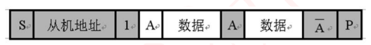 (the shaded part indicates that the data is transmitted from the master to the slave, and the unshaded part indicates that the data is transmitted from the slave to the master. A indicates response, and a non indicates non response (high level). S represents the start signal and P represents the end signal.)
The general process is similar to that from the host to the slave. We can understand it by analogy. What we should pay attention to is who sends the data and response signals.
2, Practical application
1. I2C drive 4-wire 0.96 inch OLED display
I believe you are no stranger to this module. It is small and low-power, and has a wide range of applications. At present, there are many implementation source codes of this module in STM32F1 series, but there are few implementation source codes in STM32F4 series. Many people still don't know how to transplant or fail to transplant, so they can regard it as a semi open source.
Don't say much, start talking about ideas!
In fact, it is configured according to the corresponding communication process and relevant protocols mentioned above, and then combined with the OLED data manual, write the function of transplantation display.
The flow chart driving this module is the communication process from the host to the slave. Play the chart again (put your conscience on the public screen)
The communication process can be configured according to the following code. I think the comments are very clear.
/*********************OLED Write data************************************/
void OLED_WrDat(unsigned char IIC_Data)
{
	IIC_Start();   //Start signal
  IIC_Send_Byte(0x78);			//Determine slave address
	IIC_Wait_Ack();
  IIC_Send_Byte(0x40);			//Determine the read-write bit and write it as 0
	IIC_Wait_Ack();	          //Slave response
  IIC_Send_Byte(IIC_Data);  //Start writing data to the slave
	IIC_Wait_Ack();           //Slave response
	IIC_Stop();               //Stop signal
}
Definition of start signal:
void IIC_Start(void)
{
	SDA_OUT();     //sda line output
	IIC_SDA=1;
	IIC_SCL=1;
	delay_us(2);
 	IIC_SDA=0;     //START:when CLK is high,DATA change form high to low
	delay_us(2);
	IIC_SCL=0;     //Clamp the I2C bus and prepare to send or receive data
}
Definition of stop signal:
void IIC_Stop(void)
{
	SDA_OUT();//sda line output
	IIC_SCL=0;
	IIC_SDA=0;//STOP:when CLK is high DATA change form low to high
 	delay_us(2);
	IIC_SCL=1;
	IIC_SDA=1;//Send I2C bus end signal
	delay_us(2);
}
Waiting for response signal:
//Wait for the response signal
//Return value: 1. Failed to receive the response
//        0, the response is received successfully

u8 IIC_Wait_Ack(void)
{
	u8 ucErrTime=0;
	SDA_IN();      //SDA set as input
	IIC_SDA=1;delay_us(1);
	IIC_SCL=1;delay_us(1);

	while(READ_SDA)
	{
		ucErrTime++;
		if(ucErrTime>250)
		{
			IIC_Stop();
			return 1;
		}
	}
	IIC_SCL=0;//Clock output 0
	return 0;
}
Definition of valid response and invalid response:
//Generate ACK response
void IIC_Ack(void)
{
	IIC_SCL=0;
	SDA_OUT();
	IIC_SDA=0;
	delay_us(4);
	IIC_SCL=1;
	delay_us(4);
	IIC_SCL=0;
}

//No ACK response is generated
void IIC_NAck(void)
{
	IIC_SCL=0;
	SDA_OUT();
	IIC_SDA=1;
	delay_us(4);
	IIC_SCL=1;
	delay_us(4);
	IIC_SCL=0;
}
According to the data manual, some display functions can be written as follows:
void OLED_ShowChar(u8 x,u8 y,u8 chr,u8 Char_Size)
{
	unsigned char c=0,i=0;
		c=chr-' ';//Get the offset value
		if(x>128-1){x=0;y=y+2;}
		if(Char_Size ==16)
			{
			OLED_Set_Pos(x,y);
			for(i=0;i<8;i++)
			OLED_WrDat(F8X16[c*16+i]);
			OLED_Set_Pos(x,y+1);
			for(i=0;i<8;i++)
			OLED_WrDat(F8X16[c*16+i+8]);
			}
			else {
				OLED_Set_Pos(x,y);
				for(i=0;i<6;i++)
				OLED_WrDat(F6x8[c][i]);

			}
}
//m^n function
u32 oled_pow(u8 m,u8 n)
{
	u32 result=1;
	while(n--)result*=m;
	return result;
}
//Display 2 numbers
//x. Y: starting point coordinates
//len: number of digits
//Size: font size
//Mode: mode 	 0, filling mode; 1. Superposition mode
//num: value (0 ~ 4294967295);
void OLED_ShowNum(u8 x,u8 y,u32 num,u8 len,u8 size2)
{
	u8 t,temp;
	u8 enshow=0;
	for(t=0;t<len;t++)
	{
		temp=(num/oled_pow(10,len-t-1))%10;
		if(enshow==0&&t<(len-1))
		{
			if(temp==0)
			{
				OLED_ShowChar(x+(size2/2)*t,y,' ',size2);
				continue;
			}else enshow=1;

		}
	 	OLED_ShowChar(x+(size2/2)*t,y,temp+'0',size2);
	}
}
//Displays a character string
void OLED_ShowString(u8 x,u8 y,u8 *chr,u8 Char_Size)
{
	unsigned char j=0;
	while (chr[j]!='\0')
	{		OLED_ShowChar(x,y,chr[j],Char_Size);
			x+=8;
		if(x>120){x=0;y+=2;}
			j++;
	}
}

//------------Display Chinese------------------
void OLED_ShowCHinese(u8 x,u8 y,u8 no)
{
	u8 t,adder=0;
	OLED_Set_Pos(x,y);
    for(t=0;t<16;t++)
		{
				OLED_WrDat(Hzk[2*no][t]);
				adder+=1;
     }
		OLED_Set_Pos(x,y+1);
    for(t=0;t<16;t++)
			{
				OLED_WrDat(Hzk[2*no+1][t]);
				adder+=1;
      }
}
Of course, remember to initialize the module before using it! The initialization function is as follows:
/*********************OLED Initialize************************************/
void OLED_Init(void)
{
	delay_ms(500);//The delay before initialization is very important!
	OLED_WrCmd(0xae);//--turn off oled panel
	OLED_WrCmd(0x00);//---set low column address
	OLED_WrCmd(0x10);//---set high column address
	OLED_WrCmd(0x40);//--set start line address  Set Mapping RAM Display Start Line (0x00~0x3F)
	OLED_WrCmd(0x81);//--set contrast control register
	OLED_WrCmd(Brightness); // Set SEG Output Current Brightness
	OLED_WrCmd(0xa1);//--Set SEG / column mapping 0xa0 left and right reverse 0xa1 normal
	OLED_WrCmd(0xc8);//Set COM / row scan direction 0xc0 upside down 0xc8 normal
	OLED_WrCmd(0xa6);//--set normal display
	OLED_WrCmd(0xa8);//--set multiplex ratio(1 to 64)
	OLED_WrCmd(0x3f);//--1/64 duty
	OLED_WrCmd(0xd3);//-set display offset	Shift Mapping RAM Counter (0x00~0x3F)
	OLED_WrCmd(0x00);//-not offset
	OLED_WrCmd(0xd5);//--set display clock divide ratio/oscillator frequency
	OLED_WrCmd(0x80);//--set divide ratio, Set Clock as 100 Frames/Sec
	OLED_WrCmd(0xd9);//--set pre-charge period
	OLED_WrCmd(0xf1);//Set Pre-Charge as 15 Clocks & Discharge as 1 Clock
	OLED_WrCmd(0xda);//--set com pins hardware configuration
	OLED_WrCmd(0x12);
	OLED_WrCmd(0xdb);//--set vcomh
	OLED_WrCmd(0x40);//Set VCOM Deselect Level
	OLED_WrCmd(0x20);//-Set Page Addressing Mode (0x00/0x01/0x02)
	OLED_WrCmd(0x02);//
	OLED_WrCmd(0x8d);//--set Charge Pump enable/disable
	OLED_WrCmd(0x14);//--set(0x10) disable
	OLED_WrCmd(0xa4);// Disable Entire Display On (0xa4/0xa5)
	OLED_WrCmd(0xa6);// Disable Inverse Display On (0xa6/a7)
	OLED_WrCmd(0xaf);//--turn on oled panel
	OLED_Fill(0x00); //Initial screen clearing
	OLED_Set_Pos(0,0);
}
In this way, the OLED display screen is configured. I have debugged it and the personal test is available.
2. I2C drives MS5837 pressure sensor
Due to the needs of Da Chuang, I searched for this sensor for a long time to find a module that meets the requirements. Maybe you can't use it, but its driving principle is the same as that of other modules.
The driver of this module is similar to OLED, which only needs to rewrite the address bit and read-write bit.
unsigned long MS583703BA_getConversion(uint8_t command)
{

			unsigned long conversion = 0;
			u8 temp[3];

	    IIC_Start();
			IIC_Send_Byte(0xEC); 		//Write address
			IIC_Wait_Ack();
			IIC_Send_Byte(command); //Write conversion command
			IIC_Wait_Ack();
			IIC_Stop();

			delay_ms(10);
			IIC_Start();
			IIC_Send_Byte(0xEC); 		//Write address
			IIC_Wait_Ack();
			IIC_Send_Byte(0);				// start read sequence
			IIC_Wait_Ack();
			IIC_Stop();

			IIC_Start();
			IIC_Send_Byte(0xEC+0x01);  //Enter receive mode
			IIC_Wait_Ack();
			temp[0] = IIC_Read_Byte(1);  //Read data bit with ACK 23-16
			temp[1] = IIC_Read_Byte(1);  //Read data bit with ACK 8-15
			temp[2] = IIC_Read_Byte(0);  //Read data bit 0-7 with NACK
			IIC_Stop();

			conversion = (unsigned long)temp[0] * 65536 + (unsigned long)temp[1] * 256 + (unsigned long)temp[2];
			return conversion;

}
I'll introduce so much about I2C. Maybe there are many unclear statements in the article. Please point out or contact me to make progress together and move forward to the embedded siege lion!!!