Push pull output:
We can roughly understand it from the word "push-pull". Push: push the level to high level Pull: pull the level to low level
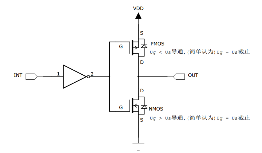
If the high level (1) is input at the INT end, it changes to low level (0) through the inverter. At this time, the PMOS tube is turned on and OUT outputs high level
(the current can reach 25mA), on the contrary, NMOS tube turns on and outputs low level.
Open drain output:
Open drain output can only output low level( (PMOS tube removed)
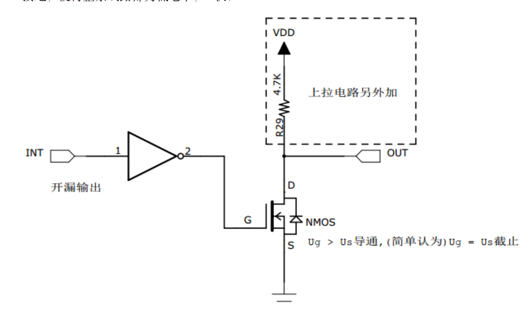
In open drain output mode, the upper P-MOS tube does not work at all. If the control output is 0 and low level, the P-MOS transistor is closed and the N-MOS transistor is turned on to ground the output. If the control output is 1 (it cannot directly output high level), both P-MOS transistor and N-MOS transistor are closed, so the pin outputs neither high level nor low level, which is a high resistance state. For normal use, the external pull-up resistor must be connected. Refer to the equivalent circuit in the open drain circuit in the figure. It has "line and" characteristics, that is, if many open drain mode pins are connected together, only when all pins output high resistance state, the high level is provided by the pull-up resistor, and the high level voltage is the voltage of the power supply connected to the external pull-up resistor. If one of the pins is low, the line is equivalent to short circuit grounding, so that the whole line is low, 0 V
Open drain output is generally used in I2C, SMBUS communication and other bus circuits that need "line and" function. In addition, it is also used in the case of level mismatch. If you need to output a high level of 5V, you can connect a pull-up resistor externally, the pull-up power supply is 5V, and set the GPIO to open drain mode. When the high resistance state is output, the pull-up resistor and the power supply output a level of 5V
typedef enum
 {
   GPIO_Mode_AIN = 0x0, // Analog input
   GPIO_Mode_IN_FLOATING = 0x04, // Floating input
   GPIO_Mode_IPD = 0x28, // Drop down input
   GPIO_Mode_IPU = 0x48, // Pull up input
   GPIO_Mode_Out_OD = 0x14, // Open drain output
   GPIO_Mode_Out_PP = 0x10, // Push pull output
   GPIO_Mode_AF_OD = 0x1C, // Multiplexed open drain output
   GPIO_Mode_AF_PP = 0x18 // Multiplexed push-pull output
 } GPIOMode_TypeDef;
In the firmware library, GPIO has a total of 8 subdivided working modes, which can be roughly classified into the following three categories:
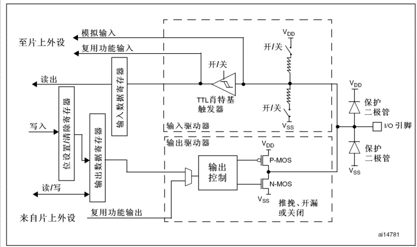
1. Input mode (simulation/Float in the air/Pull up/drop-down ) In input mode, the Schmitt trigger is turned on and the output is disabled,
You can enter the data register GPIOx_IDR read I/O Status. The input mode can be set as pull-up
 There are four types: pull-down, floating and analog input. Pull-up and pull-down inputs are well understood. The default level is determined by pull-up or pull-down
 Yes. The level of floating input is uncertain and completely determined by external input. Generally, this is used when pressing the key
 There are two modes. Analog inputs are used for ADC Collection.

2.Output mode (push-pull/Open drain) In output mode, push-pull mode is double MOS The tube works in turn and outputs
 Data register GPIOx_ODR Controllable I/O Output high and low level. In open drain mode, only N-MOS Tube work,
The output data register can be controlled I/O Output high resistance state or low level. The output speed is configurable, with 2 MHz10MHz50MHz
 Options for. The output speed here is I/O The highest switching frequency of the supported high and low level state, the higher the supported frequency,
The higher the power consumption, if the power consumption requirements are not strict, set the speed to the maximum. In output mode, Schmidt trigger is
 Open, that is, the input is available through the input data register GPIOx_IDR Readable I/O The actual state of the.

3.Reuse function (push-pull/Open drain) In the multiplexing function mode, the output is enabled, the output speed is configurable, and can work in open drain and open drain mode
 Push pull mode, but the output signal comes from other peripherals and outputs the data register GPIOx_ODR Invalid; Input available,
It can be obtained through the input data register I/O The actual state, but the data signal is generally obtained directly from the register of the peripheral.
 Pass on GPIO The register can be changed by writing different parameters GPIO The working mode of, again, needs to be improved
 Be sure to consult when solving specific registers< STM32F10X-The register description of the corresponding peripheral in the Chinese reference manual. stay
GPIO In peripherals, control port high and low control registers CRH and CRL Each can be configured GPIO Operating mode and
 The working speed is controlled every 4 bits IO,CRH The upper eight bits of the control port, CRL The lower 8 bits of the control port,
Look specifically CRH and CRL Register description for.