Key scan
Design requirements
By means of key scanning, press key_ Press the user1 (KEY1) key to turn on the LED_GREEN, press again to turn off the LED_GREEN; Press key_ Press the user2 (key2) key to turn on the LED_YELLOW, press again to turn off the LED_YELLOW.
Basic knowledge
The front LED light controls the GPIO output, and the key reads the GPIO level to know whether the key is pressed.
There are generally two types of key detection: key scanning (similar to polling) and key interrupt (interrupt detection).
Key scanning: it is to repeatedly query the GPIO status at a short interval, so as to determine whether the value has key action. This method is simple, but it consumes resources. Key interrupt is to generate interrupt signal through key, so as to realize key detection. This method needs to use interrupt mechanism and have a certain understanding of MCU. The following key interrupt experiment will be introduced in detail
The key generally occupies a GPIO port. The key operation is known by detecting the level change of the GPIO. We check the key schematic diagram as follows
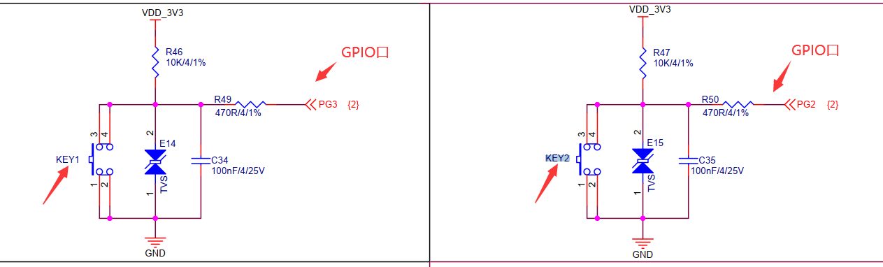 Through the schematic diagram, we can analyze that when the key is not pressed, the 3.3V VDD is directly connected to our GPIO port (PG2) through resistance, then the level of PG2GPIO port read by our MCU is high. When we press the key and the circuit on the left turns on, the level of our GPIO port is low, and the level read by MCU is low.
The commonly used keys are mechanical contact keys. When the mechanical keys are pressed or released, they will be accompanied by mechanical jitter due to the influence of mechanical elasticity, as shown below:
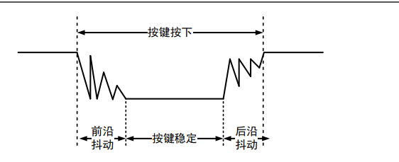
The duration of jitter is related to the mechanical switching characteristics, generally 5ms-10ms. In this dithering process, multiple high and low levels will be generated. Therefore, in order to determine the stability of the level, we need to intercept the stable level off, so we need to de dither the keys. The key jitter elimination can be processed in hardware, that is, the capacitor is connected in parallel next to the hardware to absorb the jitter level. It can also be processed by software, that is, it can avoid jitter through delay.
hardware design
There are four buttons on the development board, two of which are reset button and wake-up button. This experiment will not be introduced, which will be introduced later. The other two buttons are KEY1 and KEY2 KEY1 is connected to PG3 pin of MCU, and a C34 capacitor is connected in parallel for hardware anti chattering, and a TVS diode is connected in parallel for anti-static. Similarly, KEY2 is connected to PG2.
Stm32cube ide design
MX settings
 Note that the red and green lights here also need to be configured, just like the first experiment
Code design
driver_led.h
#ifndef DRIVER_LED_H_
#define DRIVER_LED_H_

#include "main.h"
#include "stm32mp1xx_hal.h"

#define  LED_GREEN_ON()      HAL_GPIO_WritePin(LED_GREEN_GPIO_Port, LED_GREEN_Pin, GPIO_PIN_RESET)
#define  LED_GREEN_OFF()	 HAL_GPIO_WritePin(LED_GREEN_GPIO_Port, LED_GREEN_Pin, GPIO_PIN_SET)

#define  LED_YELLOW_ON()     HAL_GPIO_WritePin(LED_YELLOW_GPIO_Port, LED_YELLOW_Pin, GPIO_PIN_RESET)
#define  LED_YELLOW_OFF()    HAL_GPIO_WritePin(LED_YELLOW_GPIO_Port, LED_YELLOW_Pin, GPIO_PIN_SET)

extern void DemoLedInit(void);
extern void LedBlinking(void);
#endif /* DRIVER_LED_H_ */
driver_key.h
#ifndef DRIVER_KEY_H_
#define DRIVER_KEY_H_
#include "driver_led.h"
#include "main.h"
#include "stm32mp1xx_hal.h"
#define PUSH_DOWN  GPIO_PIN_RESET
#define PUSH_UP    GPIO_PIN_SET

#define KEY1_READ   HAL_GPIO_ReadPin(KEY_USER1_GPIO_Port,KEY_USER1_Pin)
#define KEY2_READ	HAL_GPIO_ReadPin(KEY_USER2_GPIO_Port,KEY_USER2_Pin)

extern void Scan_key1(void);
extern void Scan_key2(void);
#endif /* DRIVER_KEY_H_ */
driver_key.c
#include "driver_key.h"
#include <stdbool.h>
static bool key1_flag=false;
static bool key2_flag=false;
void Scan_key1(void){
	if(KEY1_READ==PUSH_DOWN){//If the key is pressed
		HAL_Delay(5);//Delay for 5 seconds to eliminate chattering
		if(KEY1_READ==PUSH_DOWN){
			key1_flag=!key1_flag;
			if(key1_flag){
				LED_GREEN_ON();//Change the status of the green light
			}else{
				LED_GREEN_OFF();
			}
		}
	}
}

void Scan_key2(void){
	if(KEY2_READ==PUSH_DOWN){
		HAL_Delay(5);
		if(KEY2_READ==PUSH_DOWN){
			key2_flag=!key2_flag;
			if(key2_flag){
				LED_YELLOW_ON();
			}else{
				LED_YELLOW_OFF();
			}
		}
	}
}
main.c
int main(void)
{
  /* USER CODE BEGIN 1 */
	static uint32_t sys_freq=0;

  /* USER CODE END 1 */

  /* MCU Configuration--------------------------------------------------------*/

  /* Reset of all peripherals, Initializes the Flash interface and the Systick. */
  HAL_Init();

  /* USER CODE BEGIN Init */

  /* USER CODE END Init */

  if(IS_ENGINEERING_BOOT_MODE())
  {
    /* Configure the system clock */
    SystemClock_Config();
  }

  /* USER CODE BEGIN SysInit */

  /* USER CODE END SysInit */

  /* Initialize all configured peripherals */
  MX_GPIO_Init();
  /* USER CODE BEGIN 2 */
  sys_freq=HAL_RCC_GetSystemCoreClockFreq();
  if(!sys_freq){
	  return -1;
  }

  /* USER CODE END 2 */

  /* Infinite loop */
  /* USER CODE BEGIN WHILE */
  while (1)
  {
    /* USER CODE END WHILE */

    /* USER CODE BEGIN 3 */
	  Scan_key1();
	  Scan_key2();

  }
  /* USER CODE END 3 */
}
experimental result
Press and release KEY2 to turn off the yellow light. Similarly, KEY1
Key interrupt
Design requirements
By means of key interruption, press KEY2 to turn on the yellow light, press again to turn off the yellow light. Similarly, press KEY1 to control the green light
Basic knowledge
-
Basic concept of interrupt
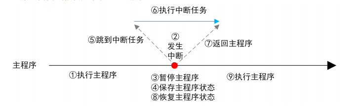
Under normal conditions, the microprocessor executes instructions in sequence according to the code content. In the process of implementation, if other emergencies need to be handled, the current task shall be temporarily determined to execute the emergency. After the emergency is handled, it shall be restored to the place just temporarily determined to continue to execute. This emergency is called interruption. The execution flow of interrupt is shown in the following figure
-
Interrupt classification
When the CPU detects illegal instructions when executing instructions, such as dividing by 0, address cross-border access, etc., it will generate an interrupt. This interrupt is an internal interrupt, also known as system exception. External events caused by CPU external devices, such as GPIO interrupt, USART interrupt, etc., are external interrupts.
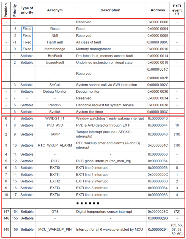
ARM CM4 core can support 256 interrupts (2 ^ 8 = 256, indicating that an 8-bit register is used to represent interrupts), 16 internal interrupts and 240 external interrupts** For the M4 of stm32mp157, all resources of the CM4 kernel are not used, but only some are used. There are only 10 internal interrupts and 150 external interrupts, a total of 160 interrupts** As shown below
-
Interrupt priority
M4 has so many interrupts. When these interrupts occur at the same time, how should the CPU handle them? Therefore, there is the concept of interrupt priority. The smaller the interrupt priority level, the higher the priority.
Preemption priority: M4 supports nested interrupts, so when the CPU is performing an interrupt, if an interrupt with higher priority comes, the CPU will immediately take the interrupt with higher execution priority
Response priority: when interrupts with the same priority occur at the same time, the one whose response priority is higher will execute first, and the other will wait for the last execution to be executed. -
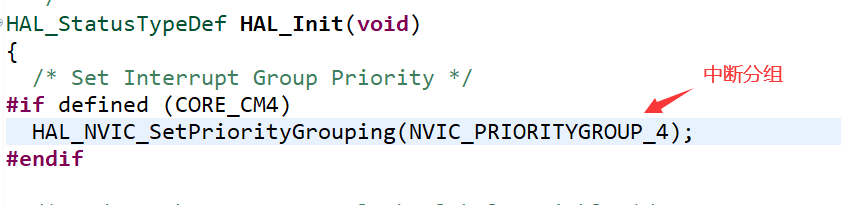
Grouping of interrupt priority
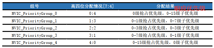 This requires us to design according to the actual situation
 -
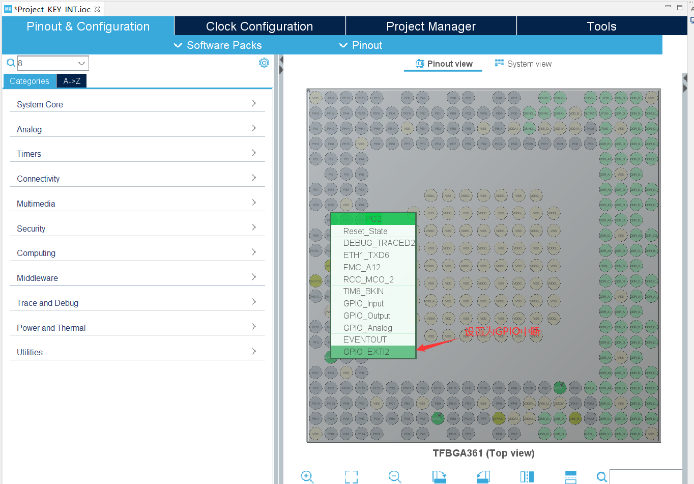
GPIO interrupt
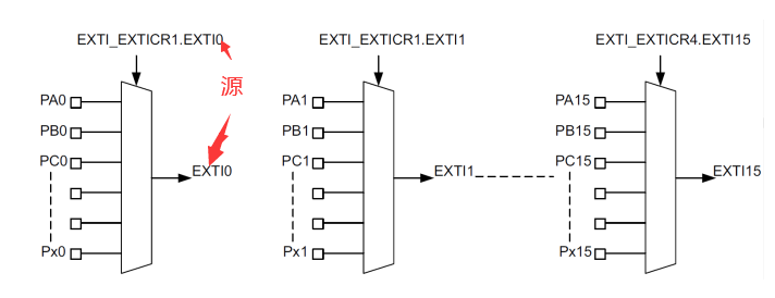
STM32MP157 has 10 groups of gpios including PA-PI and PZ, and each group of GPIO has 16 GPIO ports ranging from 0 to 15. Gpios (PA0, PB0.PC0...) with the same digital number share an interrupt source. As shown below
hardware design
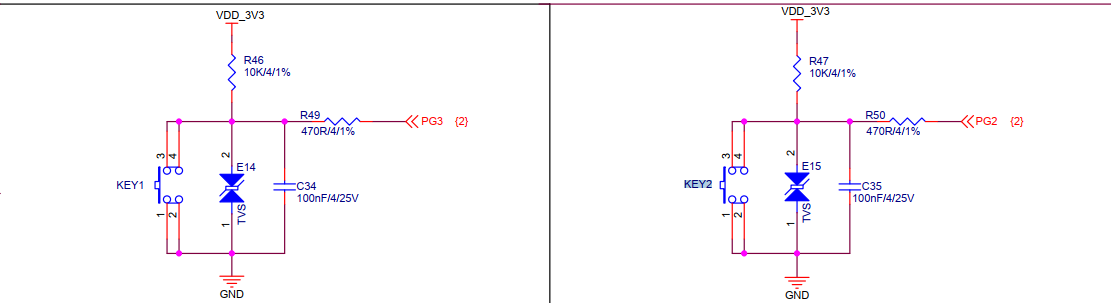
Is the schematic diagram of the key, the same as the scanning experiment above
Stm32cube ide design
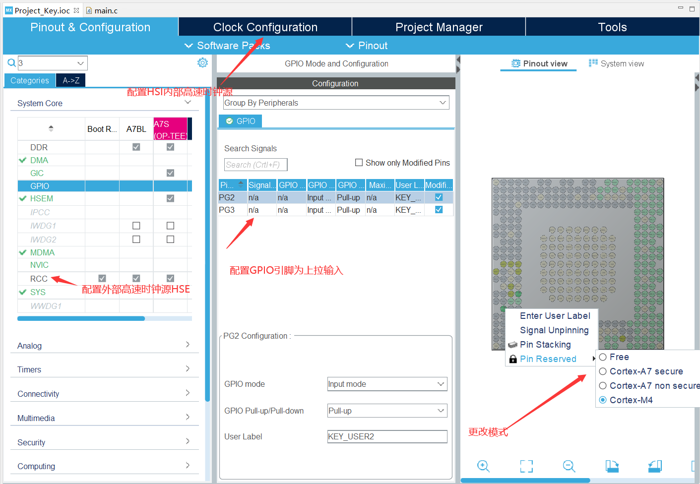
MX settings

Code design
GPIO_init.c
static void MX_GPIO_Init(void)
{
  GPIO_InitTypeDef GPIO_InitStruct = {0};

  /* GPIO Ports Clock Enable */
  __HAL_RCC_GPIOG_CLK_ENABLE();//Clock enable
  __HAL_RCC_GPIOA_CLK_ENABLE();

  /*Configure GPIO pin Output Level */
  HAL_GPIO_WritePin(LED_GREEN_GPIO_Port, LED_GREEN_Pin, GPIO_PIN_RESET);//Initialize green light

  /*Configure GPIO pin Output Level */
  HAL_GPIO_WritePin(LED_YELLOW_GPIO_Port, LED_YELLOW_Pin, GPIO_PIN_RESET);

  /*Configure GPIO pins : KEY_USER3_Pin KEY_USER2_Pin */
  GPIO_InitStruct.Pin = KEY_USER3_Pin|KEY_USER2_Pin;
  GPIO_InitStruct.Mode = GPIO_MODE_IT_RISING;//Rising edge trigger interrupt
  GPIO_InitStruct.Pull = GPIO_NOPULL;
  HAL_GPIO_Init(GPIOG, &GPIO_InitStruct);

  /*Configure GPIO pin : LED_GREEN_Pin */
  GPIO_InitStruct.Pin = LED_GREEN_Pin;
  GPIO_InitStruct.Mode = GPIO_MODE_OUTPUT_PP;
  GPIO_InitStruct.Pull = GPIO_PULLUP;
  GPIO_InitStruct.Speed = GPIO_SPEED_FREQ_VERY_HIGH;
  HAL_GPIO_Init(LED_GREEN_GPIO_Port, &GPIO_InitStruct);

  /*Configure GPIO pin : LED_YELLOW_Pin */
  GPIO_InitStruct.Pin = LED_YELLOW_Pin;
  GPIO_InitStruct.Mode = GPIO_MODE_OUTPUT_PP;
  GPIO_InitStruct.Pull = GPIO_PULLUP;
  GPIO_InitStruct.Speed = GPIO_SPEED_FREQ_VERY_HIGH;
  HAL_GPIO_Init(LED_YELLOW_GPIO_Port, &GPIO_InitStruct);

  /* EXTI interrupt init*/
  HAL_NVIC_SetPriority(EXTI2_IRQn, 1, 0);
  HAL_NVIC_EnableIRQ(EXTI2_IRQn);

  HAL_NVIC_SetPriority(EXTI3_IRQn, 1, 0);
  HAL_NVIC_EnableIRQ(EXTI3_IRQn);

}
Header file
/*
 * driver_key_int.h
 *
 *  Created on: Jan 1, 2022
 *      Author: lenovo
 */

#ifndef DRIVER_KEY_INT_H_
#define DRIVER_KEY_INT_H_

#include "main.h"
#include "stm32mp1xx_hal.h"

#define LED_GREEN_ON()      HAL_GPIO_WritePin(GPIOA,GPIO_PIN_10,GPIO_PIN_RESET);
#define LED_GREEN_OFF()	  HAL_GPIO_WritePin(GPIOA,GPIO_PIN_10,GPIO_PIN_SET);

#define LED_YELLOW_ON()     HAL_GPIO_WritePin(GPIOG,GPIO_PIN_8,GPIO_PIN_RESET);
#define LED_YELLOW_OFF()    HAL_GPIO_WritePin(GPIOG,GPIO_PIN_8,GPIO_PIN_SET);

void HAL_GPIO_EXTI_Rising_Callback(uint16_t GPIO_Pin);
#endif /* DRIVER_KEY_INT_H_ */
. c Documents
/*
 * driver_key_int.c
 *
 *  Created on: Jan 1, 2022
 *      Author: lenovo
 */

#include "driver_key_int.h"
#include <stdbool.h>
static bool key1_flag=false;
static bool key2_flag=false;

void HAL_GPIO_EXTI_Rising_Callback(uint16_t GPIO_Pin){
	switch(GPIO_Pin){
	case KEY_USER1_Pin:
	{
		key1_flag=!key1_flag;
		if(key1_flag){
			LED_GREEN_ON();
		}else{
			LED_GREEN_OFF();
		}
		break;
	}

	case KEY_USER2_Pin:
	{
		key2_flag=!key2_flag;
		if(key2_flag){
			LED_YELLOW_ON();
		}else{
			LED_YELLOW_OFF();
		}
		break;
	}
	break;
	}
}
summary
come on.