the internal ADC of STM8S003 single chip microcomputer is 12 bits. Each channel of A/D conversion can perform single and continuous conversion mode.
single conversion mode means that the ADC will stop conversion after converting data once every time. If it needs to continue conversion, it needs to manually turn on the second conversion function.
continuous conversion mode means that after each conversion, the system will automatically start the second conversion without manually setting the start of the second conversion, that is, the continuous conversion mode only needs to be started once.
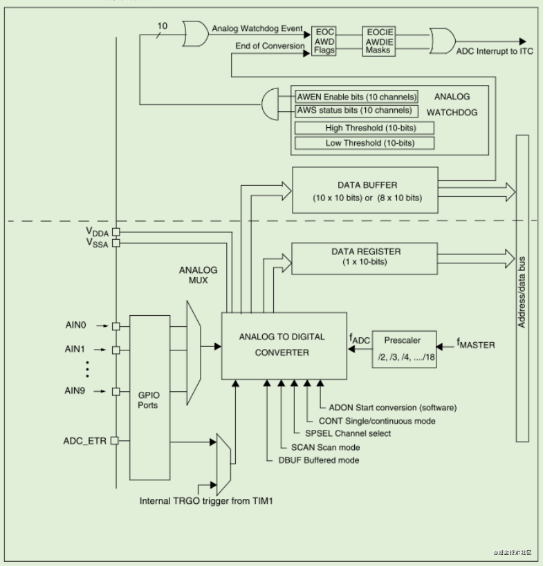
ADC block diagram is as follows:
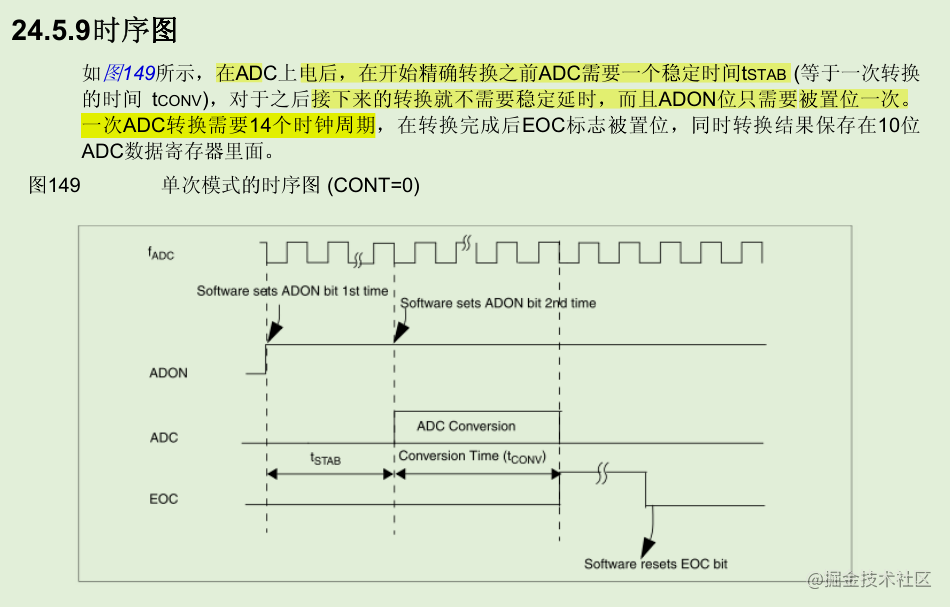
ADC conversion sequence diagram is as follows:
The following code is used to realize the single conversion mode of ADC:
#include "adc.h"
#include "main.h"

u16  DATAH = 0;                          //ADC conversion value high 8 bits
u16  DATAL = 0;                          //ADC conversion value lower 8 bits
_Bool ADC_flag = 0;                     //ADC conversion success flag

//AD channel pin initialization
void ADC_GPIO_Init( void )
{
    PD_DDR &= ~( 1 << 3 );              //PD3 is set to input current
    PD_CR1 &= ~( 1 << 3 );              //PD3 is set as suspended input
}
//ch is the corresponding pin of MCU
void ADC_CH_Init( u8 ch )
{
    char l = 0;
    ADC_CR1  = 0x00;                    //fADC = fMASTER/2, 8Mhz single conversion, conversion prohibited
    ADC_CSR  = ch + 1;                  //Control status register to select AD input channel, such as PD2(AIN3)
    ADC_CR2  = 0x00;                    //By default, when reading data with left alignment, read high first and read low
    ADC_TDRL = ( 1 << ( ch + 1 ) );     //The Schmitt trigger function 1 of the corresponding channel is prohibited to shift to the left by ch+1 bit
    ADC_CR1 |= 0x01;                    //Enable ADC and start conversion
    ADC_CSR |= 0x20;                    //EOCIE enable conversion end interrupt EOC interrupt enable
    for( l = 0; l < 100; l++ );         //Delay to ensure that the power on of ADC module is completed for at least 7us
    ADC_CR1 = ADC_CR1 | 0x01;           //Enable the ADC again at the lowest position 1 of the CR1 register and start the conversion
}

//Collect PD3 voltage value
u16 ReadVol_CH3( void )
{
    u16 voltage = 0;
    if( ADC_flag )
    {
        ADC_flag = 0;
        voltage = ( DATAH << 2 ) + DATAL ; //Get ten bit precision data 0 -- 1024
        ADC_CR1 = ADC_CR1 | 0x01;          //Start the next conversion again at the lowest position 1 of CR1 register
    };
    return voltage;
}
//AD interrupt service function interrupt number 22
#Pragma vector = 24 / / for the interrupt number in IAR, add 2 to the interrupt number in STVD
__interrupt void ADC_Handle( void )
{
    ADC_CSR &= ~0x80;                   // The conversion end flag bit is cleared EOC
    //By default, when reading data with left alignment, first read the high 8 bits and then the low 8 bits
    DATAH = ADC_DRH;                    // Read the upper 8 bits of the ADC result
    DATAL = ADC_DRL;                    // Read the lower 8 bits of the ADC result
    ADC_flag = 1;                       // ADC interrupt flag set to 1
}
A stabilization time is required when the ADC is started for the first time. Therefore, during initialization, it takes a certain time to wait for the ADC to stabilize. After it is stable, the ADC conversion can be started. Here, the interrupt is used to read the conversion result. When the ADC conversion is replaced, an interrupt will be generated. Then, the conversion result will be read in the interrupt, and the flag bit will be set at the same time. The program loops to read the flag bit. When the flag bit is 1, the conversion is completed, and the conversion result can be output. Then the ADC_ The lowest bit of CR1 register is manually set to 1 to start the next conversion.
ADC_CR1 registers are as follows:
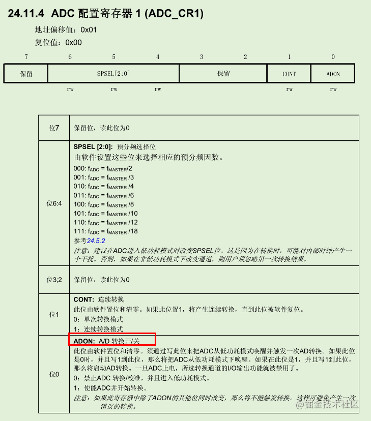
ADON bit is the conversion switch of ADC. In single mode, write 1 to ADON bit to start conversion.
Only one channel is used here. It can be seen from the top ADC block diagram that there are many channels in an ADC. What should I do if I want to collect multiple channels?
#include "adc.h"
#include "main.h"

u16  DATAH = 0;                          //ADC conversion value high 8 bits
u16  DATAL = 0;                          //ADC conversion value lower 8 bits
_Bool ADC_flag = 0;                     //ADC conversion success flag

//AD channel pin initialization
void ADC_GPIO_Init( void )
{
    PD_DDR &= ~( 1 << 3 );              //PD3 is set to input current
    PD_CR1 &= ~( 1 << 3 );              //PD3 is set as suspended input
}
//ch is the corresponding pin of MCU
void ADC_CH_Init( u8 ch )
{
    char l = 0;
    ADC_CR1  = 0x00;                    //fADC = fMASTER/2, 8Mhz single conversion, conversion prohibited
    ADC_CSR  = ch + 1;                  //Control status register to select AD input channel, such as PD2(AIN3)
    ADC_CR2  = 0x00;                    //By default, when reading data with left alignment, read high first and read low
    ADC_TDRL = ( 1 << ( ch + 1 ) );     //The Schmitt trigger function 1 of the corresponding channel is prohibited to shift to the left by ch+1 bit
    ADC_CR1 |= 0x01;                    //Enable ADC and start conversion
    //ADC_CSR |= 0x20;                    //EOCIE enable conversion end interrupt EOC interrupt enable
    for( l = 0; l < 100; l++ );         //Delay to ensure that the power on of ADC module is completed for at least 7us
    ADC_CR1 = ADC_CR1 | 0x01;           //Enable the ADC again at the lowest position 1 of the CR1 register and start the conversion
}

//Collect PD3 voltage value
u16 ReadVol_CH3( void )
{
    u16 voltage = 0;
    //If it is called only once during program initialization, the sampling speed is very fast.
    //If initialization is called every time, the speed will be 1 / 10 of the original
    ADC_CH_Init( 3 );
    while( ( ADC_CSR & 0x80 ) == 0 );      //Wait for the conversion to end
    if( ADC_CSR & 0x80 )
    {
        DATAH = ADC_DRH;                    // Read the upper 8 bits of the ADC result
        DATAL = ADC_DRL;                    // Read the lower 8 bits of the ADC result
        voltage = ( DATAH << 2 ) + DATAL ; //Get ten bit precision data 0 -- 1024
        ADC_CR1 = ADC_CR1 | 0x01;          //Start the next conversion again at the lowest position 1 of CR1 register
        ADC_CSR &= 0x7F;
    };
    return voltage;
}

//Collect PD2 voltage value
u16 ReadVol_CH4( void )
{
    u16 voltage = 0;
    //If it is called only once during program initialization, the sampling speed is very fast.
    //If initialization is called every time, the speed will be 1 / 10 of the original
    ADC_CH_Init( 2 );
    while( ( ADC_CSR & 0x80 ) == 0 );      //Wait for the conversion to end
    if( ADC_CSR & 0x80 )
    {
        DATAH = ADC_DRH;                    // Read the upper 8 bits of the ADC result
        DATAL = ADC_DRL;                    // Read the lower 8 bits of the ADC result
        voltage = ( DATAH << 2 ) + DATAL ; //Get ten bit precision data 0 -- 1024
        ADC_CR1 = ADC_CR1 | 0x01;          //Start the next conversion again at the lowest position 1 of CR1 register
        ADC_CSR &= 0x7F;
    };
    return voltage;
If multiple channels need to be converted, after one channel is converted, it needs to be reinitialized to switch the conversion channels. Since the ADC needs stabilization time after switching channels, if multiple channels switch sampling data back and forth, it is much slower than sampling data alone for one channel, because switching channels once requires waiting for a period of time to stabilize the ADC.
When data is read, the corresponding function is called directly in the main function.
#include "iostm8s103F3.h"
#include "led.h"
#include "adc.h"
#include "stdio.h"

void SysClkInit( void )
{
    CLK_SWR = 0xe1;       //HSI is the main clock source, 16MHz CPU clock frequency
    CLK_CKDIVR = 0x00;    //CPU clock 0 frequency division, system clock 0 frequency division
}

void main( void )
{
    u16 val1 = 0;
    u16 i=0;
    SysClkInit();
    __asm( "sim" );                       //Prohibit interrupt
    LED_GPIO_Init();
    ADC_CH_Init( 3 );
    __asm( "rim" );                       //Open interrupt
    while( 1 )
    {
        LED = !LED;
        val1 = ReadVol_CH3();
    }
}