catalogue
1, CAN module configuration process
1.1 set the baud rate and related working mode of can in the graphical interface
1.2 code setting can filter and interrupt
2, CAN message sending function
3, CAN information receiving function
4, CAN receive callback function
The default readers of this article have the following basic knowledge and skills:
- Have a certain understanding of can protocol and bxCAN of stm32, such as Time Quantum, four working modes, the significance of filter and its configuration parameters;
- The debugging serial port, clock and code of the chip will be configured graphically in STM32 cube ide.
Let's start the project directly (only the places related to can are described in the project).
1, CAN module configuration process
The configuration of can in STM32 is divided into two parts: the graphical interface sets the baud rate, related working mode and interrupt priority of can; The code sets the filter of can and enables FIFO interrupt. Now it is about two parts.
1.1 set the baud rate and related working mode of can in the graphical interface
- Firstly, enable the can module;
- Then adjust the parameters of "Prescaler (for Time Quantum)", "Time Quanta in Bit Segment 1" and "Time Quanta in Bit Segment 2" to make Baud Rate reach the appropriate value;
- Then select the loopback mode in the Operating Mode option (of course, the selection of the working mode depends on the specific application). Please find the materials to learn the knowledge of the loopback mode of can transceiver in stm32;
- After that, if there are no special requirements for other parameters left in the "Parameter Settings" page, it is OK to keep the default. See Figure 1-1.
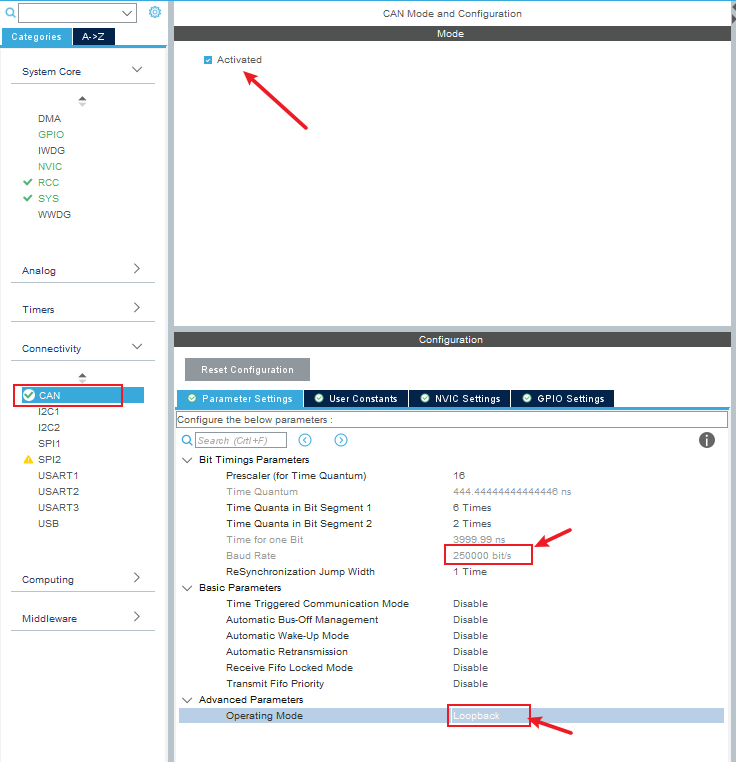 Figure 1-1
5. Enter "NVIC Settings" and check RX0 interrupt enable, as shown in Figure 1-2; And set its interrupt priority in the NVIC column on the left side of the software, as shown in Figure 1-3.
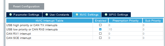 Figure 1-2
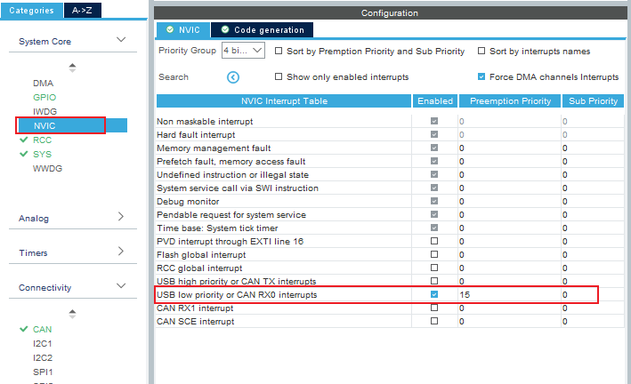 Figure 1-3
6. Here, all that can be configured in the graphical page are configured. Of course, the configuration of can filter has not been carried out, which is in the next part.
1.2 code setting can filter and interrupt
Find can in the code automatically generated by the software C file, which contains some information about the can configuration of the project, which is consistent with our configuration information in the graphical interface just now.
For convenience, we directly in MX_ CAN_ Add the filter configuration to init() function and enable the corresponding receive FIFO interrupt, as shown in Figure 1-3. Don't forget to define the required structure variables outside the function!!!
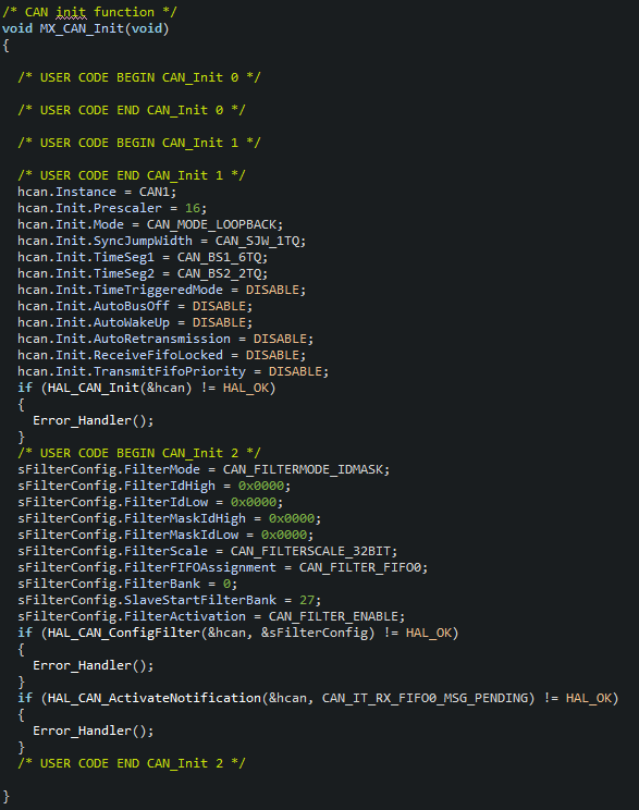 Figure 1-3
At this point, all can configurations are OK.
Now you just need to call the function Hal in main()_ CAN_ Start(), you can start can and make it work.
2, CAN message sending function
To send information, you need to use the function HAL_CAN_AddTxMessage(), I'll encapsulate it here for better use:
CAN_TxHeaderTypeDef Tx_pHeader;
/*
 * @brief: CAN Send Message.
 * @param: "TxData[]" stored the message of ready to send, which length must between 0 and 8.
 * @param: "length" stored the number of the data (one data is 8 bit) of ready to send.
 * @retval: Tx_Error: send error; other: the mailbox which has been used, this parameter can be a CAN_TX_MAILBOX0,
 * 																						   CAN_TX_MAILBOX1,
 * 																						   CAN_TX_MAILBOX2.
 */
uint32_t CAN_TX_Message(uint8_t TxData[], uint8_t length)
{

	uint32_t TxMailboxNumber = 0x00000000U;

	Tx_pHeader.StdId = 0x000;    // Send with this ID
	Tx_pHeader.ExtId = 0x0000;    // Extension ID (useless here)
	Tx_pHeader.IDE = CAN_ID_STD;    // Standard frame
	Tx_pHeader.RTR = CAN_RTR_DATA;    // Data frame
	Tx_pHeader.DLC = length;    // Length of data sent
	Tx_pHeader.TransmitGlobalTime = DISABLE;

	if(HAL_CAN_AddTxMessage(&hcan, &Tx_pHeader, TxData, &TxMailboxNumber) != HAL_OK)
	{
		return Tx_Error;
	}
	return TxMailboxNumber;
}
3, CAN information receiving function
Similarly, to accept the information on can, you need to use the function HAL_CAN_GetRxMessage(), I also repackage it:
CAN_RxHeaderTypeDef Rx_pHeader;
/*
 * @brief: CAN Receive Message.
 * @param: "RxData[]" will store the message which has been received, which length must between 0 and 8.
 * @retval: receive status.
 */
uint32_t CAN_RX_Message(uint8_t RxData[])
{

	uint8_t aData[8];

	Rx_pHeader.StdId = 0x000;	// Receive ID (useless here, can receive all ID numbers)
	Rx_pHeader.ExtId = 0x0000;
	Rx_pHeader.IDE = CAN_ID_STD;	// Receive standard frame
	Rx_pHeader.DLC = 8;		// Receive 8 8bit data
	Rx_pHeader.RTR = CAN_RTR_DATA;	// Receive data frame
	Rx_pHeader.FilterMatchIndex = 0;	// Use filter No. 0
	Rx_pHeader.Timestamp = 0;

	if(HAL_CAN_GetRxMessage(&hcan, CAN_RX_FIFO0, &Rx_pHeader, aData) != HAL_OK)
	{
		return Rx_Error;
	}
	else
	{
		// Fetch the received data
		for(uint8_t i = 0; i<Rx_pHeader.DLC; i++)
		{
			RxData[i] = aData[i];
		}
		return Rx_OK;
	}
}
4, CAN receive callback function
Callback function is a user function executed after interruption. There are multiple callback functions of can. If you want to know the information of each callback function of can, please find the answer in Chapter 5.
Because FIFO0 is configured in the filter to receive information, the callback function corresponding to FIFO0 must be used here:
uint8_t RxData[8] = {0};

void HAL_CAN_RxFifo0MsgPendingCallback(CAN_HandleTypeDef *hcan)
{

	if(hcan->Instance == CAN1)
	{
		if(CAN_RX_Message(RxData) != Rx_OK)
		{
			Error_Handler();
		}
		else
		{
			printf("MCU Received CAN Data: ");
			for(uint8_t i = 0; i<8; i++)
			{
				printf("%d ", RxData[i]);
				printf("\n\r");
				printf("\n\r");
			}
		}
	}
}
5, Summary
The can configuration and use process of stm32 is as follows in stm32cubeide software:
- Enable can graphically in ioc file and configure its baud rate, working mode and interrupt priority;
- After automatically generating code, in can C add the filter configuration in the file and enable FIFO interrupt;
- In main In main() under C file, start can first, and then send information;
- In main User defined interrupt callback function outside main() under C file.
Summary of mistakes I encountered:
- If can is not started, it cannot send or receive messages—— Read stm32f1xx_ hal_ can. According to the description of can peripherals in C file, the problem is found and solved.
- If FIFO interrupt is not enabled, can will not be interrupted—— The interrupt callback function is used to control the LED on and off, and the full speed debugging is carried out. The problem is found and solved.
- The callback function is used incorrectly. Nothing happens after the can interrupt—— Through the single-step debugging of the software, the problem is found and solved.
All functions related to can, their functions, the meaning, type, value and return value of transfer parameters; All structures related to can, their definitions, the meaning, type and value of member variables, or other more information. Please refer to these two documents in the project by yourself: