1, Display system foundation
Hardware terminology
1) Layer: a layer processing unit that can process an input image. It is divided into video and ui types according to the supported image formats.
2) Channel: a hardware channel, including several layer processing units, which can process several (typical 4) layers with the same format at the same time.
3) alpha: transparency, which determines the transparency of the corresponding image when mixing.
4) transform: image transformation, such as translation, rotation, etc.
5) Overlay: image overlay, the effect of stacking images together in order. If the one with large z-order approaches the observer, it will block the one with small z-order.
6) Blending: image blending, the effect of combining images according to alpha scale.
7) enhance: image enhancement, the process or method of purposefully processing image data to improve the image effect.
8) Capture: screen capture to save the output of de to a local file.
9) de: Display Engine, which is used to manage and display layers. It supports HDMI, TV, LCD, and other output modes. It is a hardware module responsible for stacking, mixing, scaling and other processing of input multiple layers. It not only supports the linux standard framebuffer interface, but also supports a variety of display effect processing, such as alpha, colorkey, image enhancement, brightness, contrast, saturation and chroma adjustment.
Software terminology
1) fb: frame buffer, an interface provided by linux for display devices, abstracts the display memory into a device.
2) al: abstraction layer, which abstracts the underlying hardware into a software layer of fixed business logic.
3) Low level: the bottom layer, the software layer that directly operates the hardware registers.
2, Sunxi platform DE engine
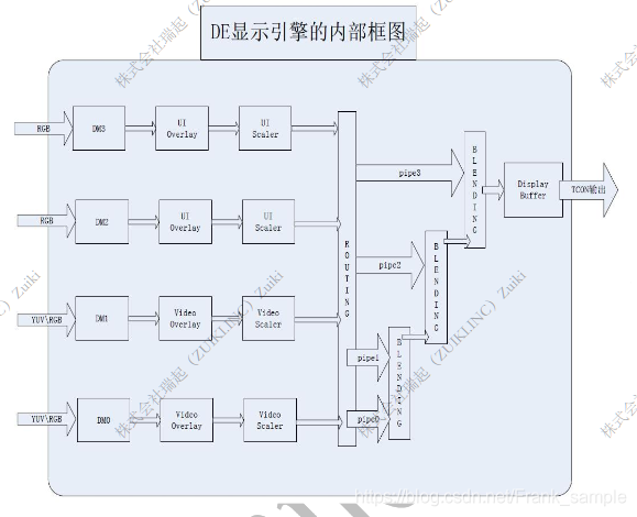
The functions supported by DE modules in different processors are different. A typical DE module supports one display channel. The display channel supports four channels that can perform alpha blending operation. The sorting between channels can be controlled by the Z value. The larger the Z value, the higher it is. Each channel supports four layer s that can be used for overlay operation. However, the four display channels are not completely consistent. Channel 0 and channel 1 are called Video channel, which supports the input of YUV and RGB data format; channel 2 and channel 3 are called UI channel, which only supports the input of RGB data format. The internal flow chart of a typical DE display engine is as follows:
Typical demo of DE layer operation:
/* Set the layer parameters, and disphd is the display driver handle */
unsigned long arg[3];

/* struct disp_layer_config The structure corresponds to all the information of a layer*/
struct disp_layer_config config;
unsigned int width = 1280;
unsigned int height = 800;
unsigned int ret = 0;

memset(&config, 0, sizeof(struct disp_layer_config));
/* Select the channel required by the layer and the parameters of this layer */
config.channel = 0;
config.layer_id = 0;
config.info.enable = 1;
config.info.mode = LAYER_MODE_BUFFER;
config.info.fb.addr[0] = (unsigned long long)mem_in; //FB physical address
config.info.fb.size[0].width = width;
config.info.fb.size[0].height = height;
config.info.fb.align[0] = 4; //4bytes align
config.info.fb.format = DISP_FORMAT_ARGB_8888

/* crop Represents the size of the crop region */
config.info.fb.crop.x = 0;
config.info.fb.crop.y = 0;
/* Fixed point decimal. The high 32bit is an integer and the low 32bit is a decimal */
config.info.fb.crop.width = ((unsigned long)width) << 32;
config.info.fb.crop.height = ((unsigned long)height) << 32;

config.info.fb.flags = DISP_BF_NORMAL;
config.info.fb.scan = DISP_SCAN_PROGRESSIVE;
config.info.alpha.mode = 2;//global pixel alpha
config.info.alpha.value = 0xff;//global alpha value

/* Display window size */
config.info.screen_win.x = 0;
config.info.screen_win.y = 0;
config.info.screen_win.width = width;
config.info.screen_win.height = hieght;
config.info.id = 0;

/* The upper layer calls the ioctl interface used by the DE display engine */
arg[0] = 0; //screen_id 0 indicates the selection path 0
arg[1] = (unsigned long)&config;
arg[2] = 1;//Indicates that the number of layers is set to 1
ret = ioctl(disphd, DISP_LAYER_SET_CONFIG, (void *)arg);
3, G2D
G2D mainly realizes acceleration functions such as image scaling, data format, color space conversion and image synthesis (including alpha, colorkey, rotate, mirror, rop, maskblt).
Because some functions coincide with DE, G2D hardware rotation function is generally used in actual use. For example, when APP is horizontal and LCD is vertical, if only the UI is rotated, the software rotation function of DE can be considered. Once big data rotation such as video is involved, G2D hardware rotation function is generally used, which has higher efficiency and low CPU resources.
Dual channel display scheme
1) Basic display content
Taking the monitor used in the monitoring field as an example, the graphical interface content of the general output device includes:
- GUI Graphical Interface: the whole GUI interface contains many contents, such as split line, time, current mode, etc.
- Video video monitoring interface: the real-time monitoring interface of the camera.
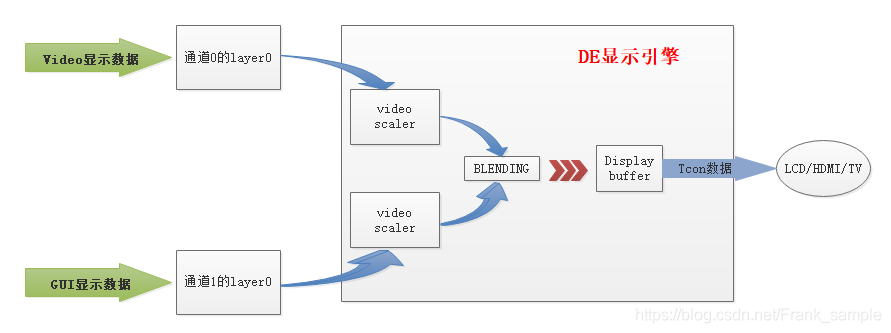
2) Processing scheme of dual channel display
DE has two UI channels and two Video channels. Each channel has four layers. Synthesis can be done between layers and alpha blending can be done between channels.
Specific implementation scheme: a Video channel is used to realize the display of GUI interface, and the four layers in the Video channel can be further subdivided, and each layer is used to realize the display of special elements. Another Video channel is used to display the Video interface. Finally, the two channels are synthesized to obtain the final output content to the display device.
At the same time, in order to prevent one FB buffer from being drawn and displayed at the same time, it is recommended to use FB double buffer mechanism. Its principle is to allocate two buffers of the same size for FB as video memory to alternately draw and display. If DE is displaying buffer 2, the object drawn this time is buffer 1, and then for FB standard mode, you can use FB pan_ The display call notifies DE to display buffer 1.
Single channel scheme
1) Basic display content
When there is no need to display the Video interface, but only simple GUI display, such as menu bar, status bar, background box and other display contents, in this case, the single channel display scheme can be used, and each channel supports the superimposed display of up to four layers.
2) Processing scheme of single channel display
The four layers in each channel are layer0~3. The four layers in the channel can be overlay ed. The default priority is layer3 > layer2 > layer1 > layer0, that is, layer3 has the highest priority in this channel. Based on this principle, the GUI interface can be divided into four large elements and drawn into their respective layers. Finally, the content can be synthesized together through the default priority to obtain the final GUI display interface. You can also draw all GUI display data into a layer.
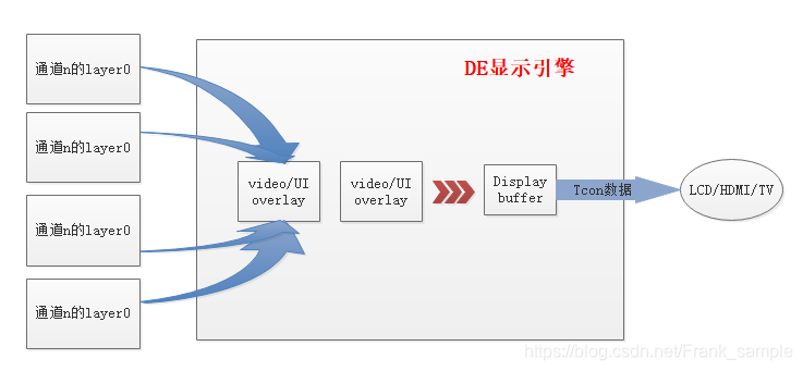
Note: due to drawing error, the layer numbers of channel n in the above figure are 0 ~ 3 respectively