catalogue
2. Introduction to hardware wiring
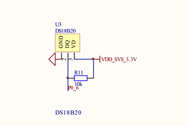
2.1 DS18B20 temperature sensor
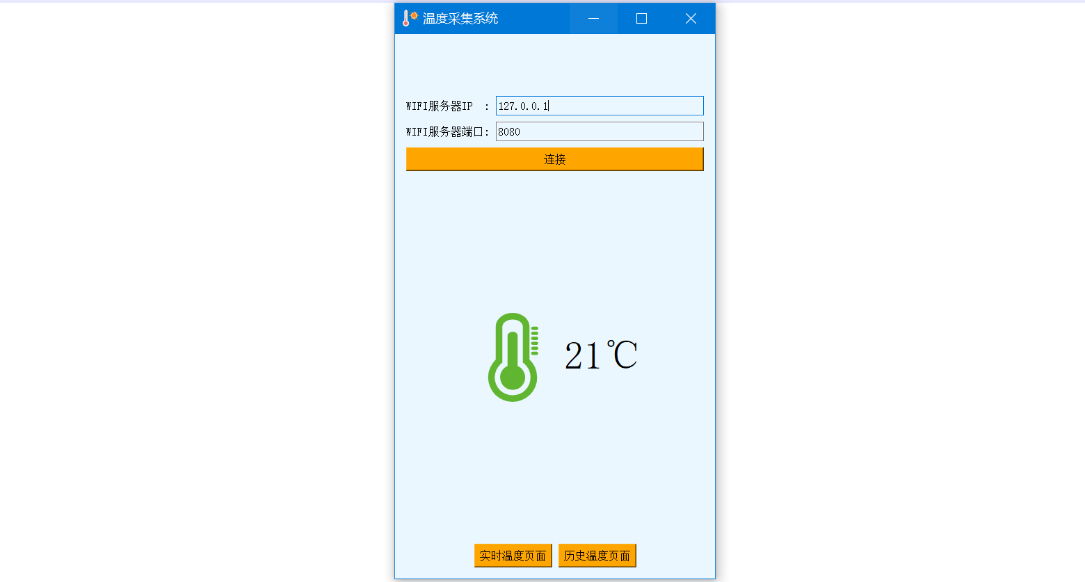
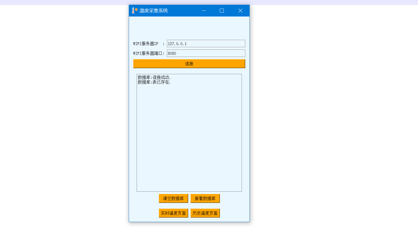
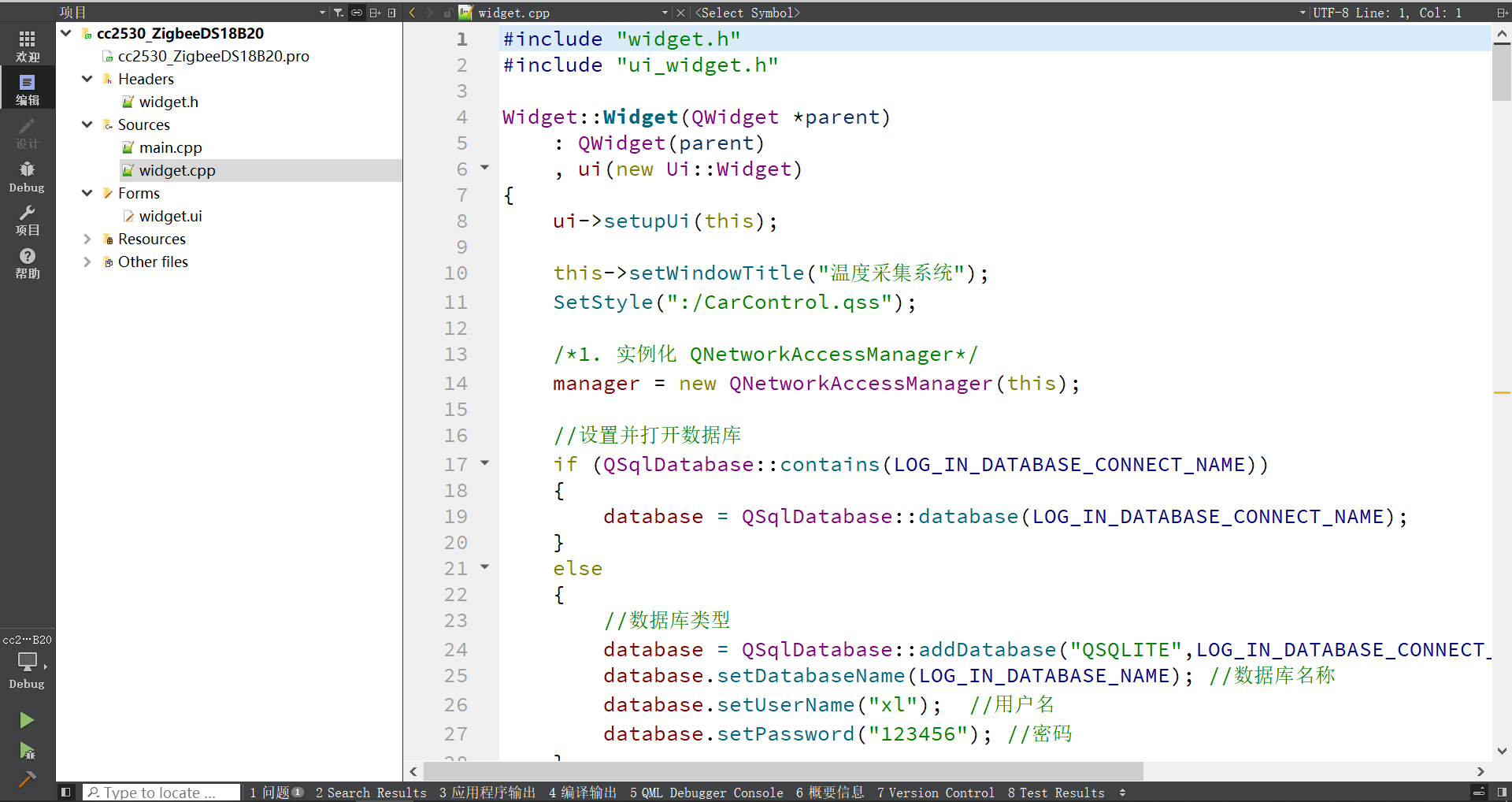
3.1 upper computer of QT design
1. Function introduction
This is a remote temperature alarm designed based on CC2530. The ambient temperature is detected through CC2530 terminal and uploaded to mobile APP for real-time display.
There are two CC2530 development boards, which are called board a (as coordinator) and board B (as temperature node). Board a is connected with ESP8266 WIF module for communication with mobile APP. The DS18B20 temperature sensor module is connected to board B to transmit the detected temperature to board A. after receiving the temperature of DS18B20, board a sends it to the mobile phone APP for display. The APP host computer adopts Qt framework design and supports cross platform. Android, windows, IOS and Linux can be compiled, run and installed.
Download address of complete project code: The temperature alarm is designed based on CC2530(ZigBee) zip - embedded document class resources - CSDN Download
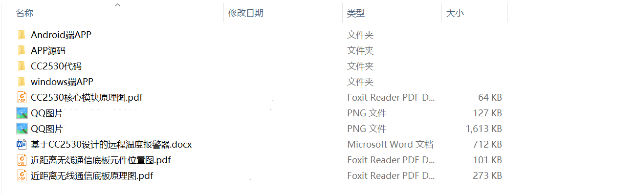
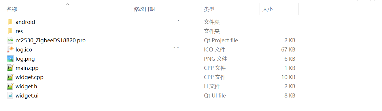
The package contains:
2. Introduction to hardware wiring
2.1 DS18B20 temperature sensor
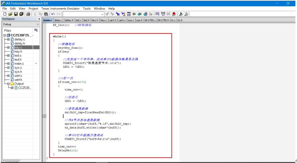
As node B, the CC2530 development board is connected with DS18B20 temperature sensor to collect the temperature and transmit it to node A.
This is the program of node B. the DS18B20 temperature data is collected once A second in the main function, and then transmitted to node A.
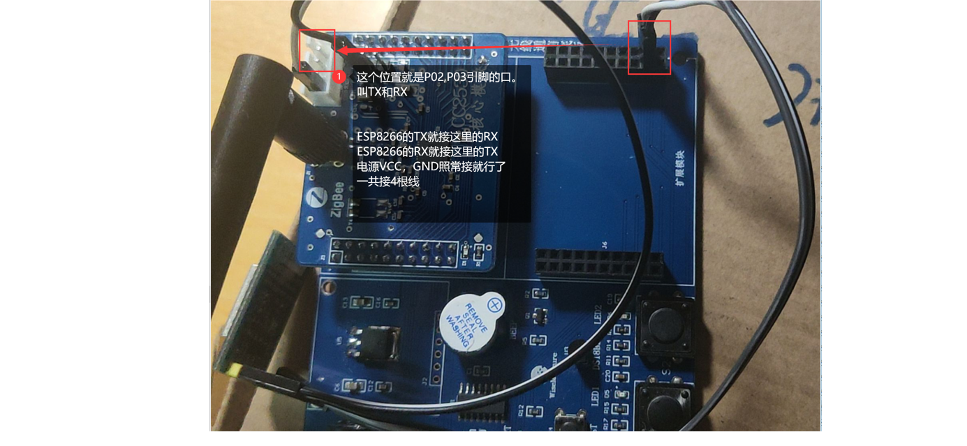
2.2 ESP8266 WIFI module
As the coordinator of node A, the CC2530 development board uses two serial ports:
(1) Serial port 0 - as a regular debugging serial port, you can print debugging information to the serial port debugging assistant.
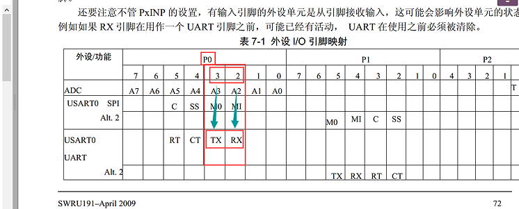
(2) Serial port 1 - connect ESP8266 WIFI for communication. P0.4,P0.5 as serial port
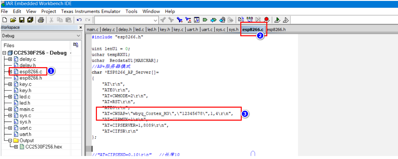
The above figure is a screenshot of the code. Set the AP hotspot name and password of ESP8266. After connecting the ESP8266, download the program. Under normal circumstances, ESP8266 will create a file named "wbyq"_ Cortex_ M3 "hotspot. The connection password is" 12345678 ". This is to open the mobile APP, search the WIFI name, and then connect. After connecting, open the special mobile APP, click connect server, and then you can receive the temperature data sent by ESP8266.
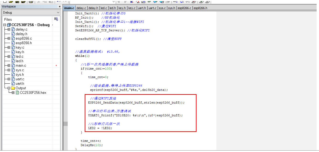
The following is the temperature of DS18B20 uploaded to the APP at the frequency of 1 second in the main function of the code.
3. Case code
3.1 upper computer of QT design
3.2 node B DS18B20 code
#define Ds18b20IO P0_6 / / temperature sensor pin
void Delay_us(unsigned int k)//us delay function
{
T1CC0L = 0x06;
T1CC0H = 0x00;
T1CTL = 0x02;
while(k)
{
while(!(T1CNTL >= 0x04));
k--;
}
T1CTL = 0x00; //off timer
}
void Delay_ms(unsigned int k)
{
T1CC0L = 0xe8;
T1CC0H = 0x03;
T1CTL = 0x0a; //Mode 32 frequency division
while(k)
{
while(!((T1CNTL >= 0xe8)&&(T1CNTH >= 0x03)));
k--;
}
T1CTL = 0x00; //off timer
}
void Delay_s(unsigned int k)
{
while(k)
{
Delay_ms(1000);
k--;
}
}
//The clock frequency is 32M
void Ds18b20Delay(unsigned int k)
{
unsigned int i,j;
for(i=0;i<k;i++)
for(j=0;j<2;j++);
}
void Ds18b20InputInitial(void)//Set port as input
{
P0DIR &= (1<<6); //P0.7 to P0 I/O direction of 0 0 input 1 output
}
void Ds18b20OutputInitial(void)//Set port as output
{
P0DIR |= (1<<6);
}
//ds18b20 returns 0x00 for successful initialization and 0x01 for failure
unsigned char Ds18b20Initial(void)
{
unsigned char Status = 0x00;
unsigned int CONT_1 = 0;
unsigned char Flag_1 = 1;
Ds18b20OutputInitial();
Ds18b20IO = 1; //DQ reset
Ds18b20Delay(260); //Delay slightly
Ds18b20IO = 0; //Single chip microcomputer pulls DQ down
Ds18b20Delay(750); //The accurate delay is greater than 480us and less than 960us
Ds18b20IO = 1; //Pull up bus
Ds18b20InputInitial();//Set IO input
while((Ds18b20IO != 0)&&(Flag_1 == 1))//Waiting for ds18b20 response, with the function of preventing timeout
{ //Wait for about 60ms
CONT_1++;
Ds18b20Delay(10);
if(CONT_1 > 8000)Flag_1 = 0;
Status = Ds18b20IO;
}
Ds18b20OutputInitial();
Ds18b20IO = 1;
Ds18b20Delay(100);
return Status; //Return to initialization status
}
void Ds18b20Write(unsigned char infor)
{
unsigned int i;
Ds18b20OutputInitial();
for(i=0;i<8;i++)
{
if((infor & 0x01))
{
Ds18b20IO = 0;
Ds18b20Delay(6);
Ds18b20IO = 1;
Ds18b20Delay(50);
}
else
{
Ds18b20IO = 0;
Ds18b20Delay(50);
Ds18b20IO = 1;
Ds18b20Delay(6);
}
infor >>= 1;
}
}
unsigned char Ds18b20Read(void)
{
unsigned char Value = 0x00;
unsigned int i;
Ds18b20OutputInitial();
Ds18b20IO = 1;
Ds18b20Delay(10);
for(i=0;i<8;i++)
{
Value >>= 1;
Ds18b20OutputInitial();
Ds18b20IO = 0;// Pulse signal
Ds18b20Delay(3);
Ds18b20IO = 1;// Pulse signal
Ds18b20Delay(3);
Ds18b20InputInitial();
if(Ds18b20IO == 1) Value |= 0x80;
Ds18b20Delay(15);
}
return Value;
}
//Temperature reading function with 1 decimal place
float floatReadDs18B20(void)
{
unsigned char V1,V2; //Define high and low 8-bit buffers
unsigned int temp; //Define temperature buffer register
float fValue;
Ds18b20Initial();
Ds18b20Write(0xcc); // Skip reading serial number and column number
Ds18b20Write(0x44); // Start temperature conversion
Ds18b20Initial();
Ds18b20Write(0xcc); //Skip reading serial number and column number
Ds18b20Write(0xbe); //Read the temperature register (a total of 9 registers are readable). The first two are the temperature
V1 = Ds18b20Read(); //Low position
V2 = Ds18b20Read(); //high position
//temp = ((V1 >> 4)+((V2 & 0x07)*16)); // Convert data
temp=V2*0xFF+V1;
fValue = temp*0.0625;
return fValue;
}3.3 coordinator-ESP8266 code
#include "esp8266.h"
uint lenU1 = 0;
uchar tempRXU1;
uchar RecdataU1[MAXCHAR];
//AP + server mode
char *ESP8266_AP_Server[]=
{
"AT\r\n",
"ATE0\r\n",
"AT+CWMODE=2\r\n",
"AT+RST\r\n",
"ATE0\r\n",
"AT+CWSAP=\"wbyq_Cortex_M3\",\"12345678\",1,4\r\n",
"AT+CIPMUX=1\r\n",
"AT+CIPSERVER=1,8089\r\n",
"AT+CIFSR\r\n"
};
//"At + cipend = 0,10 \ R \ n" / / length 10
//After returning ">", you can send data normally
//"SEND OK" is returned after sending successfully
//send data
void ESP8266_SendData(char *p,int len)
{
char buff[50];
sprintf(buff,"AT+CIPSEND=0,%d\r\n",len);
clearBuffU1();
Uart1_Send_String(buff);
DelayMs(1000);
RecdataU1[lenU1]='\0';
UR0SendString(RecdataU1);
clearBuffU1();
//send data
Uart1_Send_String(p);
//Wait for sending to complete
DelayMs(1000);
RecdataU1[lenU1]='\0';
UR0SendString(RecdataU1);
clearBuffU1();
}
/****************************************************************************
* Name: SetWifi()
* Function: set the corresponding IO port of LED lamp
* Entry parameters: None
* Exit parameters: None
****************************************************************************/
void SetWifi(void)
{
P0DIR |= 0x40; //P0.6 is defined as output
IGT = 0; //High level reset
DelayMs(500);
IGT = 1; //Low level operation
}
/*
Set WIFI to AP mode + TCP server
*/
void SetESP8266_AP_TCP_Server()
{
clearBuffU1();
Uart1_Send_String("AT\r\n");
DelayMs(2000);
RecdataU1[lenU1]='\0';
UR0SendString(RecdataU1);
clearBuffU1();
Uart1_Send_String("ATE0\r\n");
DelayMs(2000);
RecdataU1[lenU1]='\0';
UR0SendString(RecdataU1);
clearBuffU1();
Uart1_Send_String("AT+CWMODE=2\r\n");
DelayMs(2000);
RecdataU1[lenU1]='\0';
UR0SendString(RecdataU1);
clearBuffU1();
Uart1_Send_String("AT+RST\r\n");
DelayMs(2000);
DelayMs(2000);
RecdataU1[lenU1]='\0';
UR0SendString(RecdataU1);
clearBuffU1();
Uart1_Send_String("ATE0\r\n");
DelayMs(2000);
RecdataU1[lenU1]='\0';
UR0SendString(RecdataU1);
clearBuffU1();
Uart1_Send_String("AT+CWSAP=\"wifi_cc2530\",\"12345678\",1,4\r\n");
DelayMs(2000);
RecdataU1[lenU1]='\0';
UR0SendString(RecdataU1);
clearBuffU1();
Uart1_Send_String("AT+CIPMUX=1\r\n");
DelayMs(2000);
RecdataU1[lenU1]='\0';
UR0SendString(RecdataU1);
clearBuffU1();
Uart1_Send_String("AT+CIPSERVER=1,8080\r\n");
DelayMs(2000);
RecdataU1[lenU1]='\0';
UR0SendString(RecdataU1);
clearBuffU1();
Uart1_Send_String("AT+CIFSR\r\n");
DelayMs(2000);
RecdataU1[lenU1]='\0';
UR0SendString(RecdataU1);
}
unsigned char dataRecv;
unsigned char Flag = 0;
/*===================UR1 Initialization function====================*/
void Init_Uart1()
{
PERCFG = 0x00; //Position 1 P0 4/P0. 5 ports
P0SEL |= 0x30; //P0.4,P0.5 as serial port (external device function)
U1CSR |= 0x80; //Set to UART mode
U1GCR |= 11; //BAUD_E
U1BAUD |= 216; //BAUD_M baud rate is set to 115200
UTX1IF = 0; //UART1 TX interrupt flag is initially set to 0
U1CSR |= 0X40; //Allow reception
IEN0 |= 0x88; // Turn on the general interrupt and UART1 receives the interrupt
}
void clearBuffU1(void)
{
int j;
for(j=0;j<MAXCHAR;j++)
{
RecdataU1[j]=0x00;
}
lenU1=0;
}
/*******************************************************************************
Serial port 1 sends a byte function
*******************************************************************************/
void Uart1_Send_Char(char Data)
{
U1CSR &= ~0x40; //Prohibit receiving
U1DBUF = Data;
while(UTX1IF == 0);
UTX1IF = 0;
U1CSR |= 0x40; //Allow reception
}
/*******************************************************************************
Serial port 1 send string function
*******************************************************************************/
void Uart1_Send_String(char *Data)
{
while(*Data!='\0')
{
Uart1_Send_Char(*Data);
Data++;
}
}
/****************************************************************
The serial port receives a character: once data is transmitted from the serial port to CC2530, it enters the interrupt and assigns the received data to the variable temp
****************************************************************/
#pragma vector = URX1_VECTOR
__interrupt void UART1_ISR(void)
{
if(lenU1<81)
{
tempRXU1 = U1DBUF;
RecdataU1[lenU1]=tempRXU1;
URX1IF = 0; // Clear interrupt flag
lenU1++;
}
}