1, I2c communication protocol
I2C communication protocol (Inter Integrated Circuit) has few pins, simple hardware implementation and strong scalability. It does not need external transceiver equipment of USART, CAN and other communication protocols. Now it is widely used in the communication between multiple integrated circuits (ICS) in the system.
Realizing I2C requires two signal lines to complete information exchange, SCL clock signal line and SDA data input / output line. It belongs to synchronous communication. Since the input and output data use one line, the communication direction is half duplex.
·I2C requires at least two wires, which is similar to asynchronous serial port, but can support multiple slave devices. Theoretically, an I2C can mount up to 127 devices, but it can mount up to 112 devices excluding reserved addresses.
·Different from SPI, I2C can support multi master system, allow multiple masters, and each master can communicate with all slaves (I2C communication is not allowed between masters, and each master can only use I2C bus in turn).
·The data transmission rate of I2C is between serial port and SPI. Most I2C devices support 100KHz and 400KHz modes.
There will be some additional consumption when using I2C to transmit data: for every 8 bits of data sent, an additional 1 bit of metadata (ACK or NACK) is required.
·I2C supports two-way data exchange. Since there is only one data line, the communication is half duplex. The hardware complexity is also between serial port and SPI, and the software implementation can be quite simple.
I2C physical layer
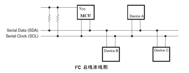
·It is a bus that supports devices. "Bus" refers to the signal line shared by multiple devices. In an I2C communication bus, multiple I2C communication devices can be connected to support multiple communication hosts and multiple communication slaves.
·An I2C bus uses only two bus lines, one bidirectional serial data line (SDA) and one serial clock line (SCL). The data line is used to represent data, and the clock line is used for data transceiver synchronization.
·Each device connected to the bus has an independent address, which can be used by the host to access different devices.
·The bus is connected to the power supply through a pull-up resistor. When the I2C device is idle, it will output the high resistance state. When all devices are idle and output the high resistance state, the pull-up resistor will pull the bus to the high level.
·When multiple hosts use the bus at the same time, in order to prevent data conflict, arbitration will be used to determine which device occupies the bus.
·There are three transmission modes: the standard mode has a transmission rate of 100kbit/s, the fast mode is 400kbit/s, and the high-speed mode can reach 3.4Mbit/s. However, most I2C devices do not support the high-speed mode at present.
I2C protocol layer
Taking the data written from the host to the slave as an example, its basic structure is shown in the figure, in sequence:
Start signal - slave address - read / write signal - data bit - reply bit -... - stop bit
Start signal (S): when SCL line is at high level, SDA line switches from high level to low level; Stop signal §: when SCL is high, SDA line switches from low level to high level.
Frame address: each device on I2C bus has its own independent address. When the host initiates communication, it sends the device address (SLAVE_ADDRESS) through SDA signal line to find the slave. I2C protocol stipulates that the device address can be 7 bits or 10 bits. In practice, 7-bit address is widely used.
I2C uses SDA signal line to transmit data and SCL signal line to synchronize data. The SDA data line transmits one bit of data in each clock cycle of SCL. During transmission, the data represented by SDA is valid when SCL is high level, that is, SDA represents data "1" at high level and data "0" at low level. When SCL is at low level, SDA data is invalid. Generally, SDA performs level switching at this time to prepare for the next presentation of data.
Both data and address transmission of I2C have response. The response includes "ack" and "NACK".
As the data receiving end, when the device (regardless of the master and slave) receives a byte data or address transmitted by I2C, if it wants the other party to continue to send data, it needs to send an "ack" signal to the other party, and the sender will continue to send the next data; If the receiving end wants to end the data transmission, it sends a "non response (N ACK)" signal to the other party. After receiving the signal, the sender will generate a stop signal to end the signal transmission.
Analysis of I2C function block diagram
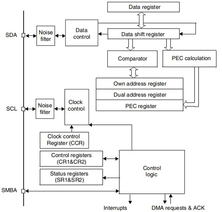
Clock control logic:
The clock signal of SCL line is controlled by I2C interface according to clock control register (CCR), and the main control parameters are clock frequency. Configuring the CCR register of I2C can modify the parameters related to the communication rate.
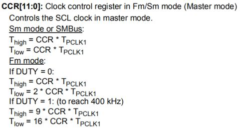
The "standard / fast" mode of I2C communication can be selected, and the two modes correspond to the communication rate of 100/400Kbit/s.
In the fast mode, the duty cycle of SCL clock can be selected, and the mode of Tlow/Thigh=2 or Tlow/Thigh=16/9 can be selected. We know that I2C protocol samples SDA signal at SCL high level, and SDA prepares the next data at SCL low level. Modifying the high-low level ratio of SCL will affect data sampling, but the proportion difference between the two modes is not large. If it is not very strict, Just choose.
There is also a 12 bit configuration factor CCR in the CCR register, which works with the input clock source of I2C peripheral to generate SCL clock. The I2C peripheral of STM32 is mounted on APB1 bus. The clock source PCLK1 of APB1 is used. The output clock formula of SCL signal line is as follows:
For example, our PCLK1=36MHz. If you want to configure the rate of 400Kbit/s, the calculation method is as follows:
PCLK clock cycle: TPCLK1 = 1/36000000
Target SCL clock cycle: TSCL = 1/400000
High level time in SCL clock cycle: height = TSCL / 3
Low level time in SCL clock cycle: TLOW = 2*TSCL/3
Calculate the value of CCR: CCR = height / tpclk1 = 30
The calculation result shows that the CCR is 30. Writing this value to the register bit can control the communication rate of IIC to 400KHz. In fact, even if the configured SCL clock is not completely equal to the standard 400KHz, the correctness of IIC communication will not be affected, because all data communication is coordinated by SCL, as long as its clock frequency is not much higher than the standard.
Data control logic:
The SDA signal of I2C is mainly connected to the data shift register. The data source and target of the data shift register are data register (DR), address register (OAR), PEC register and SDA data line. When sending data outward, the data shift register takes the "data register" as the data source and sends the data bit by bit through the SDA signal line; When receiving data from the outside, the data shift register stores the data sampled by the SDA signal line bit by bit in the "data register". If data verification is enabled, the received data will be calculated by PCE calculator, and the operation results will be stored in "PEC register". When the I2C of STM32 operates in slave mode and receives the device address signal, the data shift register will compare the received address with the value of its own "I2C address register" of STM32 in response to the addressing of the host. The self I2C address of STM32 can be modified by modifying the "self address register". It supports the simultaneous use of two I2C device addresses, which are stored in OAR1 and OAR2 respectively.
Overall control logic:
The overall control logic is responsible for coordinating the entire I2C peripherals. The working mode of the control logic changes according to the parameters of the "control register (CR1/CR2)" configured by us. When the peripheral works, the control logic will modify the "status registers (SR1 and SR2)" according to the working state of the peripheral. As long as we read the register bits related to these registers, we can understand the working state of I2C. In addition, the control logic is also responsible for controlling the generation of I2C interrupt signals, DMA requests and various I2C communication signals (start, stop, response signals, etc.) as required.
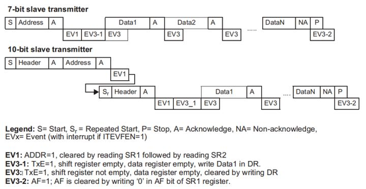
Communication process
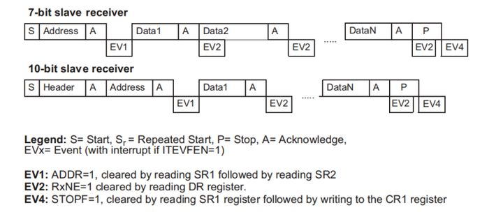
When using I2C peripheral for communication, it will write parameters to different data bits of "status register (SR1 and SR2)" at different stages of communication. We can understand the communication status by reading these register flags.
From send mode:
From receive mode:
After that, we will continue to introduce how to configure and use I2C based on STM32 and LM75A sensor (I2C), including writing and reading data using I2C.
2, Realization of AHT20 acquisition program
In the sample code provided by wildfire, open an empty project that contains only the firmware library. Add relevant codes to the project. Please refer to the following link for details of adding Codes:
https://blog.csdn.net/hhhhhh277523/article/details/111397514
Main code analysis
void  read_AHT20_once(void)
{
	delay_ms(10);

	reset_AHT20();//Reset AHT20 chip
	delay_ms(10);

	init_AHT20();//Initialize AHT20 chip
	delay_ms(10);

	startMeasure_AHT20();//Start testing AHT20 chip
	delay_ms(80);

	read_AHT20();//Read the data collected by AHT20
	delay_ms(5);
}
2.AHT20 chip reads data
void read_AHT20(void)
{
	uint8_t   i;

	for(i=0; i<6; i++)
	{
		readByte[i]=0;
	}
	I2C_Start();//I2C start

	I2C_WriteByte(0x71);//I2C write data
	ack_status = Receive_ACK();//Received response information
	readByte[0]= I2C_ReadByte();//I2C read data
	Send_ACK();//Send response information

	readByte[1]= I2C_ReadByte();
	Send_ACK();

	readByte[2]= I2C_ReadByte();
	Send_ACK();

	readByte[3]= I2C_ReadByte();
	Send_ACK();

	readByte[4]= I2C_ReadByte();
	Send_ACK();

	readByte[5]= I2C_ReadByte();
	SendNot_Ack();
	//Send_ACK();

	I2C_Stop();//I2C stop function
	//Judge whether the first byte read is 0x08, which is specified in the chip reading process. If there is no problem in the reading process, process the read data accordingly
	if( (readByte[0] & 0x68) == 0x08 )
	{
		H1 = readByte[1];
		H1 = (H1<<8) | readByte[2];
		H1 = (H1<<8) | readByte[3];
		H1 = H1>>4;

		H1 = (H1*1000)/1024/1024;

		T1 = readByte[3];
		T1 = T1 & 0x0000000F;
		T1 = (T1<<8) | readByte[4];
		T1 = (T1<<8) | readByte[5];

		T1 = (T1*2000)/1024/1024 - 500;

		AHT20_OutData[0] = (H1>>8) & 0x000000FF;
		AHT20_OutData[1] = H1 & 0x000000FF;

		AHT20_OutData[2] = (T1>>8) & 0x000000FF;
		AHT20_OutData[3] = T1 & 0x000000FF;
	}
	else
	{
		AHT20_OutData[0] = 0xFF;
		AHT20_OutData[1] = 0xFF;

		AHT20_OutData[2] = 0xFF;
		AHT20_OutData[3] = 0xFF;
		printf("Read failed!!!");

	}
	printf("\r\n");
	//According to the calculation formula of temperature and humidity in AHT20 chip, the final result is obtained and displayed through serial port
	printf("temperature:%d%d.%d",T1/100,(T1/10)%10,T1%10);
	printf("humidity:%d%d.%d",H1/100,(H1/10)%10,H1%10);
	printf("\r\n");
}
3, Temperature and humidity acquisition - OLED display
Download link: https://github.com/Sunlight-Dazzling/stm32_AHT20_OLED/tree/main/User/usart. Here is the complete project code
, add the checked file to the project
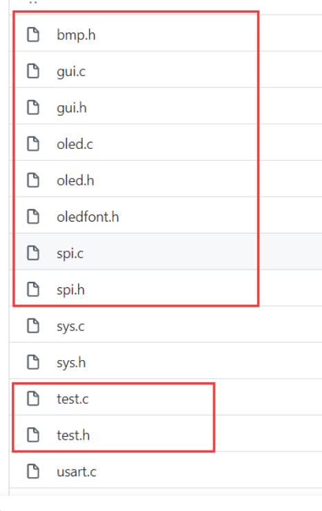
bsp_ Add the following code to I2C. C
#include "bsp_i2c.h"
#include "delay.h"

uint8_t   ack_status=0;
uint8_t   readByte[6];
uint8_t   AHT20_status=0;

uint32_t  H1=0;  //Humility
uint32_t  T1=0;  //Temperature

uint8_t t1,t2,t3,t4;
uint8_t h1,h2,h3;

uint8_t  AHT20_OutData[4];
uint8_t  AHT20sendOutData[10] = {0xFA, 0x06, 0x0A, 0x00, 0x00, 0x00, 0x00, 0x00, 0x00, 0xFF};
char strTemp[30];  //Declare character array strTemp, initialize element 30
char strHumi[30];  //Declare character array strHumi, initialize element 30
int t;
int h;
float a;
float b;
void read_AHT20(void)
{
	uint8_t   i;
	for(i=0; i<6; i++)
	{
		readByte[i]=0;
	}

	//-------------
	I2C_Start();

	I2C_WriteByte(0x71);
	ack_status = Receive_ACK();
	readByte[0]= I2C_ReadByte();
	Send_ACK();

	readByte[1]= I2C_ReadByte();
	Send_ACK();

	readByte[2]= I2C_ReadByte();
	Send_ACK();

	readByte[3]= I2C_ReadByte();
	Send_ACK();

	readByte[4]= I2C_ReadByte();
	Send_ACK();

	readByte[5]= I2C_ReadByte();
	SendNot_Ack();
	//Send_ACK();

	I2C_Stop();

	//--------------
	if( (readByte[0] & 0x68) == 0x08 )
	{
		H1 = readByte[1];
		H1 = (H1<<8) | readByte[2];
		H1 = (H1<<8) | readByte[3];
		H1 = H1>>4;

		H1 = (H1*1000)/1024/1024;

		T1 = readByte[3];
		T1 = T1 & 0x0000000F;
		T1 = (T1<<8) | readByte[4];
		T1 = (T1<<8) | readByte[5];

		T1 = (T1*2000)/1024/1024 - 500;

		AHT20_OutData[0] = (H1>>8) & 0x000000FF;
		AHT20_OutData[1] = H1 & 0x000000FF;

		AHT20_OutData[2] = (T1>>8) & 0x000000FF;
		AHT20_OutData[3] = T1 & 0x000000FF;
	}
	else
	{
		AHT20_OutData[0] = 0xFF;
		AHT20_OutData[1] = 0xFF;

		AHT20_OutData[2] = 0xFF;
		AHT20_OutData[3] = 0xFF;
		printf("lyy");

	}
	/*Display the collected temperature and humidity through the serial port
	printf("\r\n");
	printf("Temperature:% d%d.%d",T1/100,(T1/10)%10,T1%10);
	printf("Humidity:% d%d.%d",H1/100,(H1/10)%10,H1%10);
	printf("\r\n");*/
	t=T1/10;
	t1=T1%10;
	a=(float)(t+t1*0.1);
	h=H1/10;
	h1=H1%10;
	b=(float)(h+h1*0.1);
	sprintf(strTemp,"%.1f",a);   //Call the Sprintf function to format the temperature data of DHT11 into the string array variable strTemp
    sprintf(strHumi,"%.1f",b);    //Call the Sprintf function to format the humidity data of DHT11 into the string array variable strHumi
	GUI_ShowCHinese(16,00,16,"Temperature and humidity display",1);
	GUI_ShowCHinese(16,20,16,"temperature",1);
	GUI_ShowString(53,20,strTemp,16,1);
	GUI_ShowCHinese(16,38,16,"humidity",1);
	GUI_ShowString(53,38,strHumi,16,1);
	delay_ms(1500);
	delay_ms(1500);
}
Add the corresponding dot matrix font library in OLE font. H in gui.c. you need to find the font corresponding to the five words of temperature and humidity display
Add some code to the main function
int main(void)
{
	delay_init();	    	       //Delay function initialization
	uart_init(115200);
	IIC_Init();

	NVIC_Configuration(); 	   //Set NVIC interrupt packet 2: 2-bit preemption priority and 2-bit response priority
	OLED_Init();			         //Initialize OLED
	OLED_Clear(0);
	while(1)
	{
		//printf("temperature and humidity display");
		read_AHT20_once();
		OLED_Clear(0);
		delay_ms(1500);
  }
}
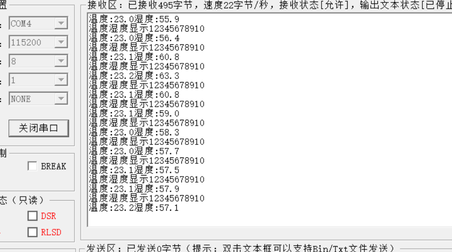
Operation results
4, OLED sliding display of long characters
Move the code horizontally left and right and add it to the main function
OLED_WR_Byte(0x2E,OLED_CMD);        //Turn off scrolling
OLED_WR_Byte(0x26,OLED_CMD);        //Scroll horizontally left or right 26 / 27
OLED_WR_Byte(0x00,OLED_CMD);        //virtual byte
OLED_WR_Byte(0x00,OLED_CMD);        //Start page 0
OLED_WR_Byte(0x07,OLED_CMD);        //Rolling interval
OLED_WR_Byte(0x07,OLED_CMD);        //Termination page 7
OLED_WR_Byte(0x00,OLED_CMD);        //virtual byte
OLED_WR_Byte(0xFF,OLED_CMD);        //virtual byte
OLED_WR_Byte(0x2F,OLED_CMD);        //Turn on scrolling
The six characters of Chongqing Jiaotong University were converted
Chongqing (0) (1) Jiaotong (2) Tongtong (3) University (4) school (5)
{0x00,0x10,0x00,0xF8,0x3F,0x00,0x01,0x00,0xFF,0xFE,0x01,0x00,0x1F,0xF0,0x11,0x10},
{0x1F,0xF0,0x11,0x10,0x1F,0xF0,0x01,0x00,0x3F,0xF8,0x01,0x00,0xFF,0xFE,0x00,0x00}, / "heavy", 0/
{0x01,0x00,0x00,0x80,0x3F,0xFE,0x20,0x00,0x20,0x80,0x20,0x80,0x20,0x80,0x2F,0xFC},
{0x20,0x80,0x21,0x40,0x21,0x40,0x22,0x20,0x42,0x20,0x44,0x10,0x88,0x08,0x10,0x06}, / "Qing", 1/
{0x02,0x00,0x01,0x00,0x01,0x00,0xFF,0xFE,0x00,0x00,0x10,0x10,0x10,0x08,0x20,0x24},
{0x48,0x24,0x04,0x40,0x02,0x80,0x01,0x00,0x02,0x80,0x0C,0x40,0x30,0x30,0xC0,0x0E}, / "handover", 2/
{0x00,0x00,0x47,0xF8,0x20,0x10,0x21,0xA0,0x00,0x40,0x07,0xFC,0xE4,0x44,0x24,0x44},
{0x27,0xFC,0x24,0x44,0x24,0x44,0x27,0xFC,0x24,0x44,0x24,0x54,0x54,0x08,0x8F,0xFE}, / "on", 3/
{0x01,0x00,0x01,0x00,0x01,0x00,0x01,0x00,0x01,0x00,0xFF,0xFE,0x01,0x00,0x01,0x00},
{0x02,0x80,0x02,0x80,0x04,0x40,0x04,0x40,0x08,0x20,0x10,0x10,0x20,0x08,0xC0,0x06}, / "big", 4/
{0x22,0x08,0x11,0x08,0x11,0x10,0x00,0x20,0x7F,0xFE,0x40,0x02,0x80,0x04,0x1F,0xE0},
{0x00,0x40,0x01,0x80,0xFF,0xFE,0x01,0x00,0x01,0x00,0x01,0x00,0x05,0x00,0x02,0x00}, / "learn", 5/
Add code in test.c
void TEST_MainPage(void)
{

	GUI_ShowCHinese(10,20,16,"chongqing jiaotong university ",1);
	//GUI_ShowString(4,48,"631907060325",16,1);
	delay_ms(1500);
	delay_ms(1500);
}
result