	The experiment was done in April in the first half of the year, but it was not posted online before. The specific project has been delivered to Github, and we need to take it by ourselves.
Link at the end of the article. If you have any help, please like it. Also welcome to reprint it. Just indicate the source! Thank you!
Experiment purpose: Modbus slave station, using RTU to communicate with PC through USB.
(because there is no 485 and 232, USB anti 232 is used, the difference is that there is no clock line. The project of github is to have read hold memory function and write multiple registers.)
Experimental equipment: MDK5, stm32ubemx, modsbu? Tool (this is the master station of modbus on the PC side)
1. First, configure the corresponding pins and generate the project
This step is generated by using stm32ubemx configuration. The main thing is that USART1 and RCC are default settings.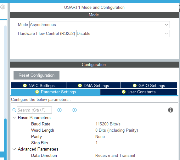
The clock uses an external input clock as long as it does not exceed the frequency range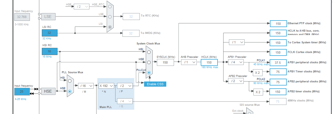
Due to the large size of the generation project, in order to save the compilation time and computer memory, we chose to generate only the required software package.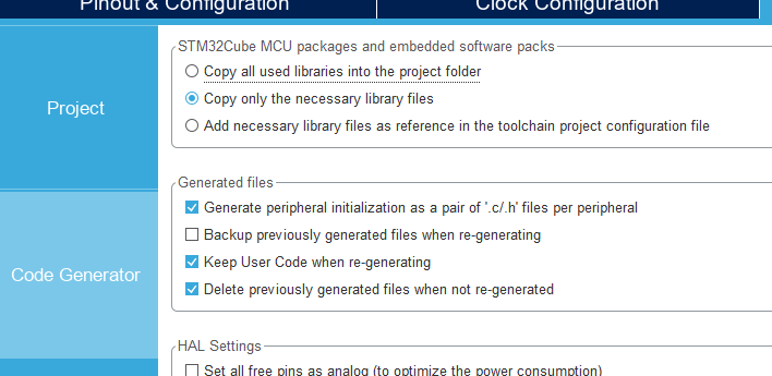
2. The next step is to modify the program
Since this is a self-made package, a. c/.h file is generated separately. And add the header file to mian.c.
/* USER CODE BEGIN Includes */
#include "stdio.h"
#include "modbutest.h"
/* USER CODE END Includes */
Add some definitions needed
/* Private variables ---------------------------------------------------------*/

/* USER CODE BEGIN PV */
	extern uint16_t DB_R[100];
	uint8_t buff1[100];
	int buff1stat=0;
	uint8_t buff2[100];
	int flag=0;
	uint8_t RxByte;

/* USER CODE END PV */
And the data stored in the register in the experiment is added to the main function.
  /* USER CODE BEGIN 1 */

	DB_R[0] = 0x0102;
	DB_R[1] = 0x0204;
	DB_R[2] = 0x0306;
	DB_R[3] = 0x0408;
	int count;
  /* USER CODE END 1 */
Because it is through serial port 1, if you need to use the serial port to receive and send.
See code for details
int main(void)
{
  /* USER CODE BEGIN 1 */

	DB_R[0] = 0x0102;
	DB_R[1] = 0x0204;
	DB_R[2] = 0x0306;
	DB_R[3] = 0x0408;
	int count;
  /* USER CODE END 1 */


  /* MCU Configuration--------------------------------------------------------*/

  /* Reset of all peripherals, Initializes the Flash interface and the Systick. */
  HAL_Init();

  /* USER CODE BEGIN Init */

  /* USER CODE END Init */

  /* Configure the system clock */
  SystemClock_Config();

  /* USER CODE BEGIN SysInit */

  /* USER CODE END SysInit */

  /* Initialize all configured peripherals */
  MX_GPIO_Init();
  MX_USART1_UART_Init();
  /* USER CODE BEGIN 2 */
	HAL_UART_Receive_IT(&huart1,&RxByte,1);
  /* USER CODE END 2 */

  /* Infinite loop */
  /* USER CODE BEGIN WHILE */
  while (1)
  {
    /* USER CODE END WHILE */

    /* USER CODE BEGIN 3 */

	if(flag==1)
	{
			ReadHoldRegister(buff1,buff2);
		if(buff1[1]==0x03)	//The first digit is the function code. Which one is the function code? Then perform the corresponding functions.
		{  //03 function code is to read register, as long as the value in the register is output
		  for(count=0;count<5+buff1[5]*2;count++)
				HAL_UART_Transmit(&huart1, &buff2[count],1,0xFFFF);
			HAL_GPIO_TogglePin(GPIOB, GPIO_PIN_0);
			HAL_Delay(100);
		}
		else if (buff1[1]==0x10)//The 10 function code is to read the multi bit register.
		//		See MODBUS protocol manual for detailed function code corresponding functions. If necessary, you can leave a message in the manual and I will send it to you.
		{
			for(count=0;count<=7;count++)//Because the input of modbus is only 8 bytes of data,
										//Therefore, only 8 bytes of data in the register are sent.
				HAL_UART_Transmit(&huart1, &buff2[count],1,0xFFFF);
			HAL_GPIO_TogglePin(GPIOB, GPIO_PIN_1);
			HAL_Delay(100);
		}

	}
	}
  /* USER CODE END 3 */
}
The main function is to judge the function code, and then carry out corresponding operations. The specific parsing message is in the called function.
Here are the specific functions
uint16_t DB_R[100];
	MB e;
	int cnt,n,bufflen,startaddr;
	uint8_t addr[100];

void ReadHoldRegister(uint8_t buffIN[100],uint8_t buffOUT[100])
{//This is the status function, which is to obtain the status specific function of function code. Each status bit in the following function can be adjusted to function code.
//And the corresponding functions can be added to achieve the desired operation.
	int i,j;
	e.stat = 0;
	for (i = 0; i < 10; i++)
	{
		modbus_onebit(buffIN[i]);

		if (e.stat == 100)
		{

		}
		if (e.stat == 0)
		{

		}
		if (e.stat == 1)
		{
			buffOUT[i]= buffIN[i];
		}
		if (e.stat == -1)
		{

		}
		if (e.stat == 2)
		{
			buffOUT[i] = buffIN[i];
		}
		if (e.stat == 3)
		{
		}
		if (e.stat == 4)
		{
			buffOUT[2] = bufflen*2;
		}
		if (e.stat == 5)
		{
			for (j = 0,n=0; j < bufflen * 2; j= j + 2,n++)
			{
				buffOUT[3 + j] = (DB_R[n+startaddr] >> 8) & 0x00FF;
				buffOUT[3 + j+1] = DB_R[n+startaddr]& 0x00FF;
			}
		}

		if (e.stat == 12)
		{
			buffOUT[i] = buffIN[i];
		}
		if (e.stat == 13)
		{
			for (j = 0,n=0; j < bufflen; j= j + 2,n++)
			{
				DB_R[n+startaddr]=(buffIN[7 + j] << 8)+buffIN[7 + j + 1];
			}
		}
	}
	if(buffIN[1]==0x03)
	CrcCheck(buffOUT,3+bufflen*2);
	else if(buffIN[1]==0x10)
	CrcCheck(buffOUT,6);

}

void  modbus_onebit(char a)//This function is to operate according to the corresponding function code. Whether to write or read, you can choose.
{
	switch (e.stat)
	{
	case 0:
		if (a == 0x01)
			e.stat = 1;
		break;
	case 1:
		if(a==0x03)
			e.stat = 2;
		if(a==0x10)
			e.stat=12;
		break;
	case 2:
		addr[cnt] = a;
		cnt++;
		e.stat = 3;
		break;
	case 3:
		addr[cnt] = a;
		cnt++;
		if (cnt > 3)
		{
			cnt = 0;
			startaddr= addr[1];
			bufflen= addr[3];
			e.stat = 4;
		}
		break;
	case 4:
		e.stat = 5;
		break;
	case 5:
		if(n==bufflen)
		e.stat = 100;
		break;
	case 6:
		e.stat = 6;
		break;
	case 7:
		e.stat = -1;
		break;
	case 8:
		e.stat = 100;
		break;
/********Write multiple registers********/
	case 12:
		addr[cnt]=a;
		cnt++;
	if(cnt>4)
	{
		cnt=0;
		startaddr= addr[1];
		bufflen= addr[4];
		e.stat = 13;	//Transfer completed
	}
	break;
	case 13:
		if(n==bufflen)
		e.stat = 100;
		break;


	}
}


void CrcCheck(unsigned char *buf,int len)//CRC check function. I won't elaborate on the principle here.
							//It means that the sender and receiver take a common number. Using the modular division.
{
	unsigned short crc = 0xFFFF;
	unsigned char i,j=0;
	while(j < len)
	{
		crc ^= buf[j];
		for(i = 0; i < 8; i++)
		{
			if(crc & 0x01)
				{
				crc >>= 1;
				crc ^= 0xA001;
				}
			else
			crc >>= 1;
		}
		j++;
	}
	buf[j] = crc % 0x100;
	buf[j+1]=crc / 0x100;
}
The general introduction of functions has been annotated in functions.
3. Verification and debugging
The next step is verification and debugging.
Burn the program in
Then connect with the main station of the computer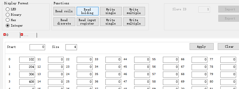
Click Read holding and take out the corresponding data in the first four readings (read and write due to multiple operations), so the displayed data is here. If you want to write multiple registers, enter the data to be input in the previous 0-3.
This is the concrete result. And then there's writing.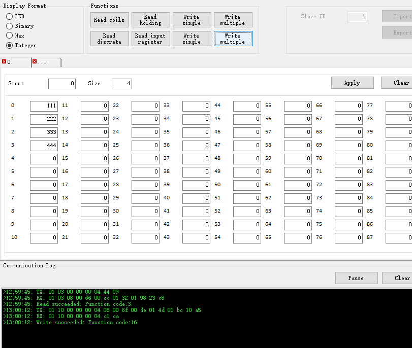
At the beginning, this writing didn't exist. At the beginning, I just made a reading. Later, my classmates added a multi write register, and then I added it.
Well, this is the end of the experiment. If you need my experiment report, you can come to me, although it's similar to this.
Then there's the link in github.
https://github.com/luxrate/Modbus_slave
Big people in need take it by themselves.
Welcome to reprint! Just indicate the source! Thank you.