Flash flash memory and other peripherals
Du Yang Studio www.DoYoung.net
Yangtao Electronic www.DoYoung.net/YT
- I hereby declare that all codes are not allowed to be duplicated or forwarded by Du Yang Studio. I only understand and comment on this program.
The last note was the use of Flash on the carambola development board, mainly for the code of carambola electronics. Interested in the basic knowledge of Flash, you can go and see:
https://blog.csdn.net/qq_40546576/article/details/99305530
The experimental results are combined with video mode:
https://www.bilibili.com/video/av64134556
This is mainly about the use of Flash flash memory. Because of this special, we need to intercept some pictures to explain, and the code is a bit long, which may cause viewing discomfort, please understand! Thank you.
explore
How large is the 16-bit unsigned data stored in each address, and we use the oled screen of the single-chip computer to display the data we access.
Requirement:
1. Displaying Data Address and Corresponding Data with OLED Display
2. Address is in the hexadecimal system of 0x and data is in the hexadecimal system.
3. Use keys to modify memory data and explore maximum values (data)
4. There are many kinds of data bits to store. How large is the standard capacity (minimum capacity) of each address?
Flash firmware library
It is suggested that small partners look at 105 pages of STM32F103 User's Manual of Firmware Function Library (Chinese). There are detailed library functions in it. This time we intercept the parts we need to understand Flash.
The Length of Flash Storage Data and the Function of Flash Writing
In the firmware library, it explains that flash stores data in three lengths: 32 bits, 16 bits and 8 bits. Maybe it's different from other programming languages we learn. It doesn't matter. Every family has its own style. The following is an explanation of firmware libraries: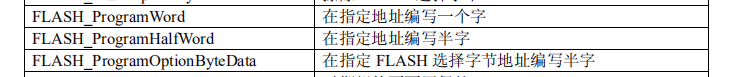
This is stm32f10x_flash.h declaration:
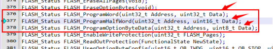
The minimum capacity data of flash is one byte (8 bit). In the following program, we use half-word (16 bit) to program.
Written functions: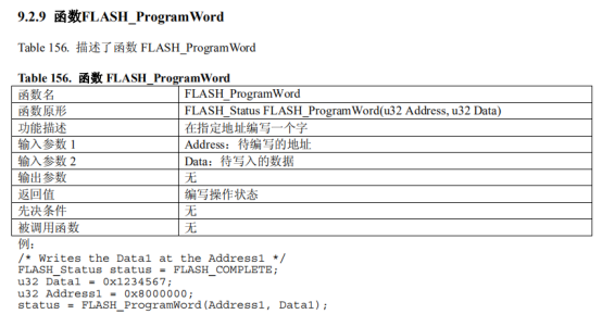
Half-character functions: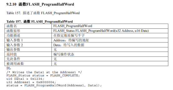
Functions that write sections: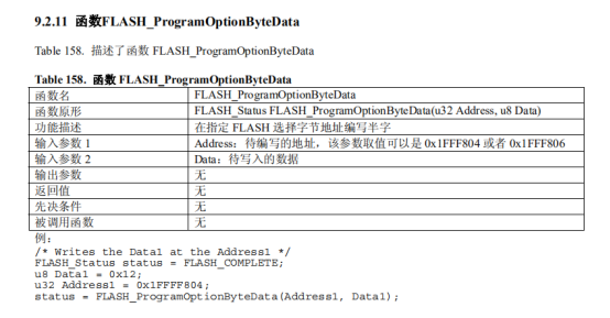
Other functions used to write Flash data
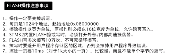
Flash memory must clear all data of the page before writing data, because STM32 flash uses NAND Flash, so the minimum data clearance can only be in pages.
1. The following is the erase function: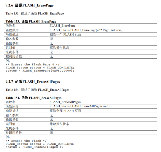
2. Unlock Flash and lock:
Flash is protected because of its limited number of erases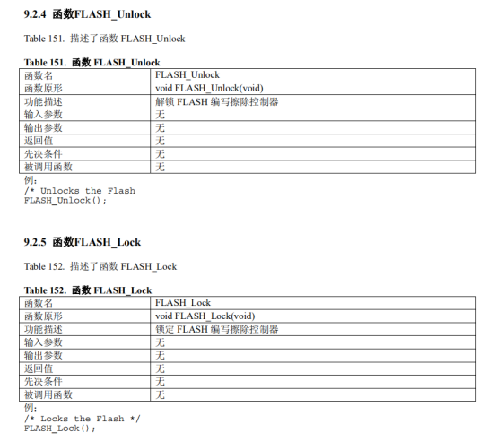
We need to unlock every time we write data, and lock every time we finish writing data. In case of misoperation.
3. Clearing Flash Markers
Why to clear the logo, I really do not know for the community, if a small partner knows, you can leave a message below! Thank you very much!!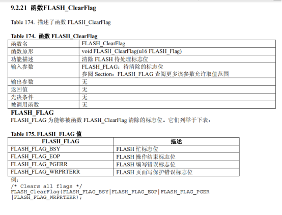
After understanding the above flash related library functions, we will explain the Flash.c file, how to write the _Flash_W function, Flash_R function should be understood.
Reading data because it does not need to write, read by oneself, so the yangtao electronics directly use the pointer method.
The following is the main code of this test:
I. Files of flash.c and flash.h
These two documents remain basically the same as last time.
flash.c file
#include "flash.h"

//FLASH Writes Data
void FLASH_W(u32 add,u16 dat){ //Parametric 1:32 bit FLASH address. Parametric 2:16-bit data
//	 RCC_HSICmd(ENABLE); //Open HSI clock
	 FLASH_Unlock();  //Unlocking FLASH Programming Erase Controller
     FLASH_ClearFlag(FLASH_FLAG_BSY|FLASH_FLAG_EOP|FLASH_FLAG_PGERR|FLASH_FLAG_WRPRTERR);//Clear the marker
     FLASH_ErasePage(add);     //Erase the specified address page
     FLASH_ProgramHalfWord(add,dat); //Write from the addr address of the specified page
     FLASH_ClearFlag(FLASH_FLAG_BSY|FLASH_FLAG_EOP|FLASH_FLAG_PGERR|FLASH_FLAG_WRPRTERR);//Clear the marker
     FLASH_Lock();    //Lock-in FLASH Programming Erase Controller
}

//FLASH Readout Data
u16 FLASH_R(u32 add){ //Parametric 1:32 reads out FLASH address. Return value: 16-bit data
	u16 a;
    a = *(u16*)(add);//Read from the addr address of the specified page
return a;
}
flash.h file
#ifndef __FLASH_H
#define __FLASH_H
#include "sys.h"


void FLASH_W(u32 add,u16 dat);
u16 FLASH_R(u32 add);

#endif
2. Write your own font CH_16x16.h
This document deleted the original documents of the Yangtao family, and used the software to get the font library that they needed, "state", "read", "write", "address" and "data".
#ifndef __CHS_16x16_H
#define __CHS_16x16_H

uc8 GB_16[] = {         // Data sheet
	  0x00,0x08,0x30,0x00,0xFF,0x20,0x20,0x20,//"Shape",
      0x20,0xFF,0x20,0x22,0x24,0x30,0x20,0x00,
      0x08,0x0C,0x02,0x01,0xFF,0x40,0x20,0x1C,
      0x03,0x00,0x03,0x0C,0x30,0x60,0x20,0x00,

	  0x04,0x04,0x84,0x84,0x44,0x24,0x54,0x8F,//"State",
      0x14,0x24,0x44,0x44,0x84,0x86,0x84,0x00,
      0x01,0x21,0x1C,0x00,0x3C,0x40,0x42,0x4C,
      0x40,0x40,0x70,0x04,0x08,0x31,0x00,0x00,

   	  0x40,0x40,0x42,0xCC,0x00,0x20,0x24,0x24,//"Read".
      0x64,0xA4,0x3F,0xE4,0x26,0xA4,0x60,0x00,
      0x00,0x00,0x00,0x7F,0x20,0x14,0x84,0x85,
      0x46,0x24,0x1C,0x27,0x44,0xC6,0x04,0x00,

      0x08,0x06,0x02,0x02,0xFA,0x22,0x22,0x22,//"Write".
      0x22,0x22,0x32,0x22,0x82,0x0A,0x06,0x00,
      0x00,0x08,0x08,0x08,0x09,0x09,0x09,0x09,
      0x09,0x4D,0x89,0x41,0x3F,0x01,0x00,0x00,

	  0x40,0x40,0xFE,0x40,0x40,0x80,0xFC,0x40,//"Land"
      0x40,0xFF,0x20,0x20,0xF0,0x20,0x00,0x00,
      0x20,0x60,0x3F,0x10,0x10,0x00,0x3F,0x40,
      0x40,0x5F,0x44,0x48,0x47,0x40,0x70,0x00,

 	  0x10,0x10,0x10,0xFF,0x10,0x18,0x10,0xF8,//"Site",
      0x00,0x00,0xFF,0x20,0x20,0x30,0x20,0x00,
      0x20,0x60,0x20,0x3F,0x10,0x50,0x48,0x7F,
      0x40,0x40,0x7F,0x40,0x40,0x60,0x40,0x00,

      0x10,0x92,0x54,0x30,0xFF,0x50,0x94,0x32,//"Number",
      0xD8,0x17,0x10,0x10,0xF0,0x18,0x10,0x00,
      0x02,0x82,0x4E,0x33,0x22,0x52,0x8E,0x40,
      0x23,0x14,0x08,0x16,0x61,0xC0,0x40,0x00,

      0x10,0x10,0x10,0xFF,0x90,0x50,0xFE,0x92,//"According to",
      0x92,0x92,0xF2,0x92,0x92,0xDF,0x82,0x00,
      0x02,0x42,0x81,0x7F,0x40,0x38,0x07,0xFC,
      0x44,0x44,0x47,0x44,0x44,0xFE,0x04,0x00
};

#endif
3. Rotary encoder encoder.c and encoder.h
Neither of them needs to be modified. Just use the carambola family.
encoder.c file
#include "encoder.h"


u8 KUP;//Knob lock sign (1 is lock)
u16 cou;

void ENCODER_Init(void){ //Interface initialization
	GPIO_InitTypeDef  GPIO_InitStructure; //Define the initial enumeration structure of GPIO
    RCC_APB2PeriphClockCmd(RCC_APB2Periph_GPIOA|RCC_APB2Periph_GPIOB|RCC_APB2Periph_GPIOC,ENABLE);
    GPIO_InitStructure.GPIO_Pin = ENCODER_L | ENCODER_D; //Select the port number
    GPIO_InitStructure.GPIO_Mode = GPIO_Mode_IPU; //Select IO Interface Working Mode//Up Resistor
	GPIO_Init(ENCODER_PORT_A,&GPIO_InitStructure);

    GPIO_InitStructure.GPIO_Pin = ENCODER_R; //Select the port number
    GPIO_InitStructure.GPIO_Mode = GPIO_Mode_IPU; //Select IO Interface Working Mode//Up Resistor
	GPIO_Init(ENCODER_PORT_B,&GPIO_InitStructure);
}

u8 ENCODER_READ(void){ //Interface initialization
	u8 a;//Store key values
	u8 kt;
	a=0;
	if(GPIO_ReadInputDataBit(ENCODER_PORT_A,ENCODER_L))KUP=0;	//Determine whether the knob is unlocked
	if(!GPIO_ReadInputDataBit(ENCODER_PORT_A,ENCODER_L)&&KUP==0){ //Determine whether the knob is rotated and whether the knob is locked.
		delay_us(100);
		kt=GPIO_ReadInputDataBit(ENCODER_PORT_B,ENCODER_R);	//Record the level status at the other end of the knob
		delay_ms(3); //delayed
		if(!GPIO_ReadInputDataBit(ENCODER_PORT_A,ENCODER_L)){ //Shake off
			if(kt==0){ //Judge left or right rotation with the other end
				a=1;//Right turn
			}else{
				a=2;//Left turn
			}
			cou=0; //Initial Lock-up Judgment Counter
			while(!GPIO_ReadInputDataBit(ENCODER_PORT_A,ENCODER_L)&&cou<60000){ //Wait for the knob to be released while accumulating the judgement to lock
				cou++;KUP=1;delay_us(20); //
			}
		}
	}
	if(!GPIO_ReadInputDataBit(ENCODER_PORT_A,ENCODER_D)&&KUP==0){ //Judge whether the knob is pressed or not
		delay_ms(20);
		if(!GPIO_ReadInputDataBit(ENCODER_PORT_A,ENCODER_D)){ //debounce
			a=3;//Add the status value of the key when the key is pressed
			//while(ENCODER_D==0); wait for the knob to open
		}
	}
	return a;
}
encoder.h file
#ifndef __ENCODER_H
#define __ENCODER_H
#include "sys.h"
#include "delay.h"

#define ENCODER_PORT_A GPIOA//Define IO Interface Group
#define ENCODER_L GPIO_Pin_6// Define IO Interface
#define ENCODER_D GPIO_Pin_7// Define IO Interface

#define ENCODER_PORT_B GPIOB//Define IO Interface Group
#define ENCODER_R GPIO_Pin_2// Define IO Interface


void ENCODER_Init(void);//Initialization
u8 ENCODER_READ(void);


#endif
IV. I2C Documents Need to be Modified
Because the I2C of the Yangtao family defaults to set the bus communication speed to 200,000, my experiment is to find that my data is not normal, so the speed is lowered to solve the problem of scrambling. Modify BusSpeed in i2c.h file and the rest will remain unchanged. Later, we will have time to explain the communication principle of I2C.
i2c.h file
#ifndef __I2C_H
#define __I2C_H
#include "sys.h"

#define I2CPORT GPIOB//Define IO Interface
#define I2C_SCL GPIO_Pin_6// Define IO Interface
#define I2C_SDA GPIO_Pin_7// Define IO Interface

#define HostAddress 0xc0//Bus Host Device Address
#define BusSpeed 100000 // Bus Speed (not higher than 400000)


void I2C_Configuration(void);
void I2C_SAND_BUFFER(u8 SlaveAddr, u8 WriteAddr, u8* pBuffer, u16 NumByteToWrite);
void I2C_SAND_BYTE(u8 SlaveAddr,u8 writeAddr,u8 pBuffer);
void I2C_READ_BUFFER(u8 SlaveAddr,u8 readAddr,u8* pBuffer,u16 NumByteToRead);
u8 I2C_READ_BYTE(u8 SlaveAddr,u8 readAddr);

#endif
i2c.c file
#include "i2c.h"


void I2C_GPIO_Init(void){ //I2C interface initialization
	GPIO_InitTypeDef  GPIO_InitStructure;
    RCC_APB2PeriphClockCmd(RCC_APB2Periph_GPIOA|RCC_APB2Periph_GPIOB|RCC_APB2Periph_GPIOC,ENABLE);
	RCC_APB1PeriphClockCmd(RCC_APB1Periph_I2C1, ENABLE); //Start I2C function
    GPIO_InitStructure.GPIO_Pin = I2C_SCL | I2C_SDA; //Select the port number
    GPIO_InitStructure.GPIO_Mode = GPIO_Mode_AF_OD; //Selecting IO Interface Working Mode
    GPIO_InitStructure.GPIO_Speed = GPIO_Speed_50MHz; //Setting IO Interface Speed (2/10/50MHz)
	GPIO_Init(I2CPORT, &GPIO_InitStructure);
}

void I2C_Configuration(void){ //I2C initialization
	I2C_InitTypeDef  I2C_InitStructure;
	I2C_GPIO_Init(); //Set the state of the GPIO interface first
	I2C_InitStructure.I2C_Mode = I2C_Mode_I2C;//Set to I2C mode
	I2C_InitStructure.I2C_DutyCycle = I2C_DutyCycle_2;
	I2C_InitStructure.I2C_OwnAddress1 = HostAddress; //Host address (slave may not use this address)
	I2C_InitStructure.I2C_Ack = I2C_Ack_Enable;//Permissible response
	I2C_InitStructure.I2C_AcknowledgedAddress = I2C_AcknowledgedAddress_7bit; //7-bit address mode
	I2C_InitStructure.I2C_ClockSpeed = BusSpeed; //Bus Speed Settings
	I2C_Init(I2C1,&I2C_InitStructure);
	I2C_Cmd(I2C1,ENABLE);//Open I2C
}

void I2C_SAND_BUFFER(u8 SlaveAddr,u8 WriteAddr,u8* pBuffer,u16 NumByteToWrite){ //I2C Send Data String (Device Address, Register, Internal Address, Number)
	I2C_GenerateSTART(I2C1,ENABLE);//Generate the starting bit
	while(!I2C_CheckEvent(I2C1,I2C_EVENT_MASTER_MODE_SELECT)); //Clear EV5
	I2C_Send7bitAddress(I2C1,SlaveAddr,I2C_Direction_Transmitter);//Sender Address
	while(!I2C_CheckEvent(I2C1,I2C_EVENT_MASTER_TRANSMITTER_MODE_SELECTED));//Clearing EV6
	I2C_SendData(I2C1,WriteAddr); //Internal function address
	while(!I2C_CheckEvent(I2C1,I2C_EVENT_MASTER_BYTE_TRANSMITTED));//Shift registers are not empty, data registers are empty, generating EV8, sending data to DR to clear the event
	while(NumByteToWrite--){ //Cyclic sending of data
		I2C_SendData(I2C1,*pBuffer); //send data
		pBuffer++; //Data pointer shift
		while (!I2C_CheckEvent(I2C1,I2C_EVENT_MASTER_BYTE_TRANSMITTED));//Clear EV8
	}
	I2C_GenerateSTOP(I2C1,ENABLE);//Generate stop signal
}
void I2C_SAND_BYTE(u8 SlaveAddr,u8 writeAddr,u8 pBuffer){ //I2C sends a byte (from address, internal address, content)
	I2C_GenerateSTART(I2C1,ENABLE); //Send Start Signal
	while(!I2C_CheckEvent(I2C1,I2C_EVENT_MASTER_MODE_SELECT)); //Waiting for completion
	I2C_Send7bitAddress(I2C1,SlaveAddr, I2C_Direction_Transmitter); //Send slave device address and status (write)
	while(!I2C_CheckEvent(I2C1,I2C_EVENT_MASTER_TRANSMITTER_MODE_SELECTED)); //Waiting for completion
	I2C_SendData(I2C1,writeAddr); //Send the internal register address of the slave device
	while(!I2C_CheckEvent(I2C1,I2C_EVENT_MASTER_BYTE_TRANSMITTED)); //Waiting for completion
	I2C_SendData(I2C1,pBuffer); //Send the content to be written
	while(!I2C_CheckEvent(I2C1,I2C_EVENT_MASTER_BYTE_TRANSMITTED)); //Waiting for completion
	I2C_GenerateSTOP(I2C1,ENABLE); //Send End Signal
}
void I2C_READ_BUFFER(u8 SlaveAddr,u8 readAddr,u8* pBuffer,u16 NumByteToRead){ //I2C reads data string (device address, register, internal address, number)
	while(I2C_GetFlagStatus(I2C1,I2C_FLAG_BUSY));
	I2C_GenerateSTART(I2C1,ENABLE);//Open signal
	while(!I2C_CheckEvent(I2C1,I2C_EVENT_MASTER_MODE_SELECT));	//Clear EV5
	I2C_Send7bitAddress(I2C1,SlaveAddr, I2C_Direction_Transmitter); //Write device address
	while(!I2C_CheckEvent(I2C1,I2C_EVENT_MASTER_TRANSMITTER_MODE_SELECTED));//Clearing EV6
	I2C_Cmd(I2C1,ENABLE);
	I2C_SendData(I2C1,readAddr); //Send Read Address
	while(!I2C_CheckEvent(I2C1,I2C_EVENT_MASTER_BYTE_TRANSMITTED)); //Clear EV8
	I2C_GenerateSTART(I2C1,ENABLE); //Open signal
	while(!I2C_CheckEvent(I2C1,I2C_EVENT_MASTER_MODE_SELECT)); //Clear EV5
	I2C_Send7bitAddress(I2C1,SlaveAddr,I2C_Direction_Receiver); //The device address is sent out and the host is read.
	while(!I2C_CheckEvent(I2C1,I2C_EVENT_MASTER_RECEIVER_MODE_SELECTED)); //Clearing EV6
	while(NumByteToRead){
		if(NumByteToRead == 1){ //Enter the if statement with only the last data left
			I2C_AcknowledgeConfig(I2C1,DISABLE); //Close the reply bit when the last data is available
			I2C_GenerateSTOP(I2C1,ENABLE);	//Enable stop bits for the last data
		}
		if(I2C_CheckEvent(I2C1,I2C_EVENT_MASTER_BYTE_RECEIVED)){ //Read data
			*pBuffer = I2C_ReceiveData(I2C1);//Call library functions to fetch data to pBuffer
			pBuffer++; //Pointer shift
			NumByteToRead--; //Bytes minus 1
		}
	}
	I2C_AcknowledgeConfig(I2C1,ENABLE);
}
u8 I2C_READ_BYTE(u8 SlaveAddr,u8 readAddr){ //I2C reads a byte
	u8 a;
	while(I2C_GetFlagStatus(I2C1,I2C_FLAG_BUSY));
	I2C_GenerateSTART(I2C1,ENABLE);
	while(!I2C_CheckEvent(I2C1,I2C_EVENT_MASTER_MODE_SELECT));
	I2C_Send7bitAddress(I2C1,SlaveAddr, I2C_Direction_Transmitter);
	while(!I2C_CheckEvent(I2C1,I2C_EVENT_MASTER_TRANSMITTER_MODE_SELECTED));
	I2C_Cmd(I2C1,ENABLE);
	I2C_SendData(I2C1,readAddr);
	while(!I2C_CheckEvent(I2C1,I2C_EVENT_MASTER_BYTE_TRANSMITTED));
	I2C_GenerateSTART(I2C1,ENABLE);
	while(!I2C_CheckEvent(I2C1,I2C_EVENT_MASTER_MODE_SELECT));
	I2C_Send7bitAddress(I2C1,SlaveAddr, I2C_Direction_Receiver);
	while(!I2C_CheckEvent(I2C1,I2C_EVENT_MASTER_RECEIVER_MODE_SELECTED));
	I2C_AcknowledgeConfig(I2C1,DISABLE); //Close the reply bit when the last data is available
	I2C_GenerateSTOP(I2C1,ENABLE);	//Enable stop bits for the last data
	a = I2C_ReceiveData(I2C1);
	return a;
}
5. Touch keys touch_key.c and touch_key.h
No need to change, just use the carambola house.
Not shown here.
...
...
6. oled.c and oled.h files
These two files add the functions they need to test.
void OLED_DISPLAY_8x16_DATA32(u8 x,u8 y,u32 w); //Data display
void OLED_DISPLAY_8x16_DATA16(u8 x,u8 y,u16 w); //Data display
void OLED_DISPLAY_8x16_DATA8(u8 x,u8 y,u8 w); //Data display
oled.h file
#ifndef __OLED_H
#define __OLED_H
#include "sys.h"
#include "i2c.h"

#Define the I2C address of OLED0561_ADD 0x78//OLED (no modification)
#define COM. 0x00//OLED directive (no modification)
#define DAT. 0x40//OLED data (no modification)

void OLED0561_Init(void);//Initialization
void OLED_DISPLAY_ON (void);//OLED Screen Open Display
void OLED_DISPLAY_OFF (void);//OLED screen shutdown display
void OLED_DISPLAY_LIT (u8 x);//OLED screen brightness setting (0~255)
void OLED_DISPLAY_CLEAR(void);//Screen clearing operation
void OLED_DISPLAY_8x16(u8 x,u8 y,u16 w);//Display a single character of 8x16
void OLED_DISPLAY_8x16_BUFFER(u8 row,u8 *str);//Display string 8x16

void OLED_DISPLAY_16x16(u8 x,u8 y,u16 w); //Chinese Character Display
void OLED_DISPLAY_PIC1(void);//pictures displaying

void OLED_DISPLAY_8x16_DATA32(u8 x,u8 y,u32 w);//data display
void OLED_DISPLAY_8x16_DATA16(u8 x,u8 y,u16 w);//data display
void OLED_DISPLAY_8x16_DATA8(u8 x,u8 y,u8 w);//data display

#endif
oled.c file, this code is omitted - omitted mainly for the carambola family code
#include "usart.h"
#include "delay.h"
#include "oled0561.h"
#include "ASCII_8x16.h"//Introduce font ASCII

#include "CHS_16x16.h"//Introduce Chinese fonts
#include "PIC1.h"//Introduce pictures

void OLED0561_Init (void){//Initialization of OLED on-screen display
	OLED_DISPLAY_OFF(); //OLED off display
	OLED_DISPLAY_CLEAR(); //Clear the screen content
	OLED_DISPLAY_ON(); //OLED Screen Initial Value Settings and Open Display
}
void OLED_DISPLAY_ON (void){//OLED Screen Initial Value Settings and Open Display
	u8 buf[28]={
	0xae,//0xae: off display, 0xaf: on display
    0x00,0x10,//Start address (double bytes)
	0xd5,0x80,//Display clock frequency?
	0xa8,0x3f,//Reuse Rate?
	0xd3,0x00,//Display offset?
	0XB0,//Write page location (0xB0-7)
	0x40,//Display start line
	0x8d,0x14,//VCC power supply
	0xa1,//Setting segment remapping?
	0xc8,//COM output mode?
	0xda,0x12,//COM output mode?
	0x81,0xff,//Contrast, instruction: 0x81, data: 0-255 (255 highest)
	0xd9,0xf1,//Charging cycle?
	0xdb,0x30,//VCC Voltage Output
	0x20,0x00,//Horizontal addressing settings
	0xa4,//0xa4: Normal display, 0xa5: Integral lighting
	0xa6,//0xa6: Normal display, 0xa7: Reverse color display
	0xaf//0xae: off display, 0xaf: on display
	}; //
	I2C_SAND_BUFFER(OLED0561_ADD,COM,buf,28);
}
....
//It's OK to omit the code that directly uses the Yangtao family.
....

/*********************************************************************************************
 * Du Yang Studio www.DoYoung.net
 * Yangtao Electronic www.DoYoung.net/YT
*********************************************************************************************/
//Mannix add code
void OLED_DISPLAY_8x16_DATA32(u8 x,u8 y,u32 w){
	u8 i,index=0;//i is the digit of the data
	u16 data[8];//Declare an array of corresponding digits to store values

	i=8;//There are 8 digits in the total.
	index=7;		   //The data of the array goes forward from the last one.
	while(i--)		   //The lowest bit of the value is put first in the last bit of the array
	{
		data[index]=w%0x10;//The lower digit of the value is placed after the array
		w/=0x10; //Remove the number of digits taken
		index--; //Array Index Runs Forward One Bit
	}

	index=0;  //Array index zeroed and array displayed in OLED at one time
	while(index!=8)
	{
		if(data[index]==0xa)//You need to determine whether it is a letter or not, and automatically recognize the letters displayed on the screen.
		{
			OLED_DISPLAY_8x16(x,y*8,'a');
		}else if(data[index]==0xb){
			OLED_DISPLAY_8x16(x,y*8,'b');
		}else if(data[index]==0xc){
			OLED_DISPLAY_8x16(x,y*8,'c');
		}else if(data[index]==0xd){
			OLED_DISPLAY_8x16(x,y*8,'d');
		}else if(data[index]==0xe){
			OLED_DISPLAY_8x16(x,y*8,'e');
		}else if(data[index]==0xf){
			OLED_DISPLAY_8x16(x,y*8,'f');
		}else{
			OLED_DISPLAY_8x16(x,y*8,data[index]+0X30);	//The number is displayed on the screen.
		}
		y++; //The complete column number of the next number, automatically changed to the next number display
		index++; //Next numerical value
    }
}
void OLED_DISPLAY_8x16_DATA16(u8 x,u8 y,u16 w){
	u8 i,index=0;//i is the digit of the data
	u16 data[4];//Declare an array of corresponding digits to store values

	i=4;//There are four digits in the total.
	index=3;		   //The data of the array goes forward from the last one.
	while(i--)		   //The lowest bit of the value is put first in the last bit of the array
	{
		data[index]=w%0x10;//The lower digit of the value is placed after the array
		w/=0x10; //Remove the number of digits taken
		index--; //Array Index Runs Forward One Bit
	}

	index=0;  //Array index zeroed and array displayed in OLED at one time
	while(index!=4)
	{
		if(data[index]==0xa)//You need to determine whether it is a letter or not, and automatically recognize the letters displayed on the screen.
		{
			OLED_DISPLAY_8x16(x,y*8,'a');
		}else if(data[index]==0xb){
			OLED_DISPLAY_8x16(x,y*8,'b');
		}else if(data[index]==0xc){
			OLED_DISPLAY_8x16(x,y*8,'c');
		}else if(data[index]==0xd){
			OLED_DISPLAY_8x16(x,y*8,'d');
		}else if(data[index]==0xe){
			OLED_DISPLAY_8x16(x,y*8,'e');
		}else if(data[index]==0xf){
			OLED_DISPLAY_8x16(x,y*8,'f');
		}else{
			OLED_DISPLAY_8x16(x,y*8,data[index]+0X30);	//The number is displayed on the screen.
		}
		y++; //The complete column number of the next number, automatically changed to the next number display
		index++; //Next numerical value
    }
}

void OLED_DISPLAY_8x16_DATA8(u8 x,u8 y,u8 w){
	u8 i,index=0;//i is the digit of the data
	u8 data[2];//Declare an array of corresponding digits to store values

	i=2;//There are four digits in the total.
	index=1;		   //The data of the array goes forward from the last one.
	while(i--)		   //The lowest bit of the value is put first in the last bit of the array
	{
		data[index]=w%0x10;//The lower digit of the value is placed after the array
		w/=0x10; //Remove the number of digits taken
		index--; //Array Index Runs Forward One Bit
	}

	index=0;  //Array index zeroed and array displayed in OLED at one time
	while(index!=2)
	{
		if(data[index]==0xa)//You need to determine whether it is a letter or not, and automatically recognize the letters displayed on the screen.
		{
			OLED_DISPLAY_8x16(x,y*8,'a');
		}else if(data[index]==0xb){
			OLED_DISPLAY_8x16(x,y*8,'b');
		}else if(data[index]==0xc){
			OLED_DISPLAY_8x16(x,y*8,'c');
		}else if(data[index]==0xd){
			OLED_DISPLAY_8x16(x,y*8,'d');
		}else if(data[index]==0xe){
			OLED_DISPLAY_8x16(x,y*8,'e');
		}else if(data[index]==0xf){
			OLED_DISPLAY_8x16(x,y*8,'f');
		}else{
			OLED_DISPLAY_8x16(x,y*8,data[index]+0X30);	//The number is displayed on the screen.
		}
		y++; //The complete column number of the next number, automatically changed to the next number display
		index++; //Next numerical value
    }
}
Seventh, the main function main.c, the important play needs everybody to taste.
Because when I write code, I like to use the standard method of University C language. The sentences are slightly longer, but the sentences are clear. Code is written by myself, annotations are also available, if you do not want to see can be directly copied. But you need the above so that the file configuration is good, the main function can run!
#Include "stm32f10x.h"//STM32 header file
#include "sys.h"
#include "delay.h"
#include "rtc.h"
#include "oled0561.h"
#include "flash.h"
#include "key.h"
#include "touch_key.h"
#include "encoder.h"


int main (void){//main program
	u8 i,k1,k2,k4,index;//i is the array variable K1 touch key A variable K2 is the touch key B K4 is the touch key D index is the array index.
	u8 b=0;	 //State Variables of Rotary Encoder
	u32 addr[8];//Declare an array of corresponding digits to store values
	u16 datas[4];//Declare Play Data Array
	u16 data;  //Declare data variables
	vu32 FLASH_START_ADDR=0x0801f000;	  //Write the starting address to modify its content

	delay_ms(100); //Wait for other devices to be ready when powered on

	ENCODER_Init();	 //Initialization of rotary encoder
	TOUCH_KEY_Init();  //Touch button initialization

	RCC_Configuration(); //System Clock Initialization
	RTC_Config(); //RTC real-time clock initialization

	I2C_Configuration();//I2C initialization

	OLED0561_Init(); //OLED initialization
	OLED_DISPLAY_LIT(100);//Brightness setting


	OLED_DISPLAY_8x16_BUFFER(0,"   FlashTest"); //display string
	OLED_DISPLAY_8x16_BUFFER(2,"Addr:"); //display string
	OLED_DISPLAY_8x16_BUFFER(4,"Data:"); //display string
	OLED_DISPLAY_16x16(6,0*16,0); //Display'shape'.
	OLED_DISPLAY_16x16(6,1*16,1);  //Display the `state'.
	OLED_DISPLAY_8x16(6,2*16,':'); //It shows: '


	/**Address becomes an array *****/
	i=8;//There are 8 digits in the total.
	index=7;		   //The data of the array goes forward from the last one.
	while(i--)		   //The lowest bit of the value is put first in the last bit of the array
	{
		addr[index]=FLASH_START_ADDR%0x10;//The lower digit of the value is placed after the array
		FLASH_START_ADDR/=0x10; //Remove the number of digits taken
		index--; //Array Index Runs Forward One Bit
	}

	/**Array to Address*****/
	index=0;		   //Array index is zero
	FLASH_START_ADDR=0;	//Empty address
	while(index!=8)		   //Numbers are placed in address variables in turn
	{
		FLASH_START_ADDR=(FLASH_START_ADDR*0x10)+addr[index]; //Push the value forward and add an array bit
		index++; //Array index runs one bit backward and needs to be changed to the lower position of address variable
	}

	/*Read Address Data****/
	data=FLASH_R(FLASH_START_ADDR);	//Reading data
	OLED_DISPLAY_8x16_DATA32(2,5,FLASH_START_ADDR); //display address
	OLED_DISPLAY_8x16_DATA16(4,5,data);		 //Display data

	/**Memory becomes an array *****/
	i=4;//There are four digits in the total.
	index=3;		   	//The address method is identical, not redundant.
	while(i--)
	{
		datas[index]=data%0x10;
		data/=0x10;
		index--;
	}

	/**Array becomes data*****/
	index=0;		   //The address method is identical, not redundant.
	data=0;
	while(index!=4)
	{
		data=(data*0x10)+datas[index];
		index++;
	}

	while(1)
	{
		/****Write Address ** Touch Key ** A ***/
		if(!GPIO_ReadInputDataBit(TOUCH_KEYPORT,TOUCH_KEY_A)){ //Read A touch button level
			k1=1;
			k2=0;
			index=7;
			OLED_DISPLAY_16x16(6,3*16,3);
			OLED_DISPLAY_16x16(6,4*16,4);
			OLED_DISPLAY_16x16(6,5*16,5);
//			OLED_DISPLAY_8x16_DATA8(4,5,data); //Display string
			while(!GPIO_ReadInputDataBit(TOUCH_KEYPORT,TOUCH_KEY_A));
		}

		/****Write Data ** Touch Key ** B ***/
		if(!GPIO_ReadInputDataBit(TOUCH_KEYPORT,TOUCH_KEY_B)){ //Reading the Level of B Touch Key
			k2=1;
			k1=0;
			index=3;
			OLED_DISPLAY_16x16(6,3*16,3);
			OLED_DISPLAY_16x16(6,4*16,6);
			OLED_DISPLAY_16x16(6,5*16,7);
//			OLED_DISPLAY_8x16_DATA32(2,5,FLASH_START_ADDR); //Display string
			while(!GPIO_ReadInputDataBit(TOUCH_KEYPORT,TOUCH_KEY_B));
		}

		/****Select Modified Number ** Touch Key ** C ***/
		if(!GPIO_ReadInputDataBit(TOUCH_KEYPORT,TOUCH_KEY_C)){ //Read C touch button level
			if(k1==1) //Whether to press a
			{
				if(index==3)
				{
					index=7;
				}else
				{
					index--;
				}

			}
			if(k2==1) //Whether to press b
			{
				if(index==0)
				{
					index=3;
				}else
				{
					index--;
				}
			}
			while(!GPIO_ReadInputDataBit(TOUCH_KEYPORT,TOUCH_KEY_C));
		}

		/****Confirm Modified Number ** Touch Key ** D ***/
		if(!GPIO_ReadInputDataBit(TOUCH_KEYPORT,TOUCH_KEY_D)){ //Read the level of D touch button
			k4=4;
		}

		/*Determine whether you need to go to the rotary encoder ** modify the address * touch the button ** D*/
		if(k4==4&&k1==1)//Determine whether to modify the address
		{
			while(k1==1){
				b=ENCODER_READ();	//Readout Rotary Encoder Value

				if(b==2)
				{
					if(addr[index]==0x0)
					{
						addr[index]=0xf;
					}else{
						addr[index]--;
					}
				}

				if(b==1)
				{
					if(addr[index]==0xf)
					{
						addr[index]=0;
					}else{
						addr[index]++;
					}
				} //Analyse the key value and add or subtract the counter value.


				if(addr[index]==0xa)//You need to determine whether it is a letter or not, and automatically recognize the letters displayed on the screen.
				{
					OLED_DISPLAY_8x16(2,(index+5)*8,'a');
				}else if(addr[index]==0xb){
					OLED_DISPLAY_8x16(2,(index+5)*8,'b');
				}else if(addr[index]==0xc){
					OLED_DISPLAY_8x16(2,(index+5)*8,'c');
				}else if(addr[index]==0xd){
					OLED_DISPLAY_8x16(2,(index+5)*8,'d');
				}else if(addr[index]==0xe){
					OLED_DISPLAY_8x16(2,(index+5)*8,'e');
				}else if(addr[index]==0xf){
					OLED_DISPLAY_8x16(2,(index+5)*8,'f');
				}else{
					OLED_DISPLAY_8x16(2,(index+5)*8,addr[index]+0X30);	//The number is displayed on the screen.
				}
				if(b==3)
				{
					k1=0;
					index=0;		   //The data of the array goes forward from the last one.
					FLASH_START_ADDR=0x0;
					while(index!=8)		   //The lowest bit of the value is put first in the last bit of the array
					{
						FLASH_START_ADDR=(FLASH_START_ADDR*0x10)+addr[index]; //Remove the number of digits taken
						index++; //Array Index Runs Forward One Bit
					}
					data=FLASH_R(FLASH_START_ADDR);
					OLED_DISPLAY_8x16_DATA16(4,5,data);
					OLED_DISPLAY_16x16(6,3*16,2);
				}

			}
			k4=0;
			OLED_DISPLAY_8x16_DATA32(2,5,FLASH_START_ADDR);
		}

		/*Determine whether it is necessary to modify the data to the rotary encoder****/
		if(k4==4&&k2==1)
		{
			while(k2==1){
				b=ENCODER_READ();	//Readout Rotary Encoder Value
				if(b==1)
				{
					if(datas[index]==0xf)
					{
						datas[index]=0;
					}else{
						datas[index]++;
					}
				} //Analyse the key value and add or subtract the counter value.
				if(b==2)
				{
					if(datas[index]==0x0)
					{
						datas[index]=0xf;
					}else{
						datas[index]--;
					}
				}

				if(datas[index]==0xa)//You need to determine whether it is a letter or not, and automatically recognize the letters displayed on the screen.
				{
					OLED_DISPLAY_8x16(4,(index+5)*8,'a');
				}else if(datas[index]==0xb){
					OLED_DISPLAY_8x16(4,(index+5)*8,'b');
				}else if(datas[index]==0xc){
					OLED_DISPLAY_8x16(4,(index+5)*8,'c');
				}else if(datas[index]==0xd){
					OLED_DISPLAY_8x16(4,(index+5)*8,'d');
				}else if(datas[index]==0xe){
					OLED_DISPLAY_8x16(4,(index+5)*8,'e');
				}else if(datas[index]==0xf){
					OLED_DISPLAY_8x16(4,(index+5)*8,'f');
				}else{
					OLED_DISPLAY_8x16(4,(index+5)*8,datas[index]+0X30);	//The number is displayed on the screen.
				}
				if(b==3)
				{
					k2=0;
					index=0;		   //The data of the array goes forward from the last one.
					data=0;
					while(index!=4)		   //The lowest bit of the value is put first in the last bit of the array
					{
						data=(data*0x10)+datas[index]; //Remove the number of digits taken
						index++; //Array Index Runs Forward One Bit
					}

					/*Write the data into the address*/
					FLASH_W(FLASH_START_ADDR,data);
//					data=FLAS H_R(FLASH_START_ADDR);
					OLED_DISPLAY_8x16_DATA16(4,5,data);
					OLED_DISPLAY_16x16(6,3*16,2);
					OLED_DISPLAY_16x16(6,4*16,6);
					OLED_DISPLAY_16x16(6,5*16,7);
				}
			}
			k4=0;
		}

		/***Scintillation program ** runs once per second ** when selecting digits**/
		RTC_Get();//Acquisition of real-time clock

		if(rsec%2&&k1==1)//Address flicker
		{
			OLED_DISPLAY_8x16(2,(index+5)*8,' ');
		}else if(k1==1){
		   	OLED_DISPLAY_8x16_DATA32(2,5,FLASH_START_ADDR); //display string
		}

		if(rsec%2&&k2==1)//Data scintillation
		{
			OLED_DISPLAY_8x16(4,(index+5)*8,' ');
		}else if(k2==1){
		   	OLED_DISPLAY_8x16_DATA16(4,5,data); //display string
		}
	}
}
The experimental results video (B station):
https://www.bilibili.com/video/av64134556
You can pay attention to the account as long as there are relevant videos, all videos are sent with this account.
Matters needing attention!