Theoretical basis of network based RSTP protocol
1, Introduction of RSTP
Although STP protocol can solve the loop problem, the slow convergence of network topology (the state in which the network can communicate) affects the user communication quality, and if the topology in the network changes frequently, the network will also lose connectivity frequently, resulting in frequent interruption of user communication, which is unbearable for users.
Due to the deficiency of STP, the 802.1w standard published by IEEE in 2001 defines RSTP. RSTP has made many improvements and optimizations on the basis of STP, which not only makes the protocol clearer and standardized, but also realizes the rapid convergence of layer-2 network topology.
Problems with STP:
1. STP initialization scenario for equipment operation
The equipment needs at least 30s from initialization to convergence. In order to prevent the emergence of temporary loop, the passive waiting timer is adopted. The calculation of STP must wait for a fixed time. STP needs at least 30s from initial state to complete convergence.
Initially, the switches will send and monitor BPDU s to each other and calculate the spanning tree
STP algorithm uses the passive wait timer timeout method to judge that all BPDU s of the whole network have been collected, and then calculate
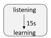
In order to avoid temporary loop, STP must wait long enough (i.e. ensure that BPDU can be sent to all nodes of the whole network synchronously) to ensure that the port status of the whole network is determined before entering forwarding.
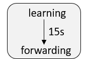
Before STP enters forwarding, it needs to build MAC address table according to the received user traffic, and it still needs to wait for the timer to timeout before entering forwarding.
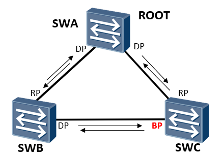
2. The switch has BP port and RP port down scenario:
When the direct link between SWC and SWA goes down, it takes at least 30s for its BP port to switch to RP port and enter the forwarding state.
In order to ensure that the topology change information has spread to the whole network and that all devices have completed the topology update, the new root port needs to wait for the timer to timeout before entering forwarding
The Blocked Port becomes a new root port and is in blocking
Status and enter the forwarding status after 2 Forward Delay times
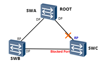
3. The switch has no BP port and the RP port is down
When the direct link between SWB and SWA goes down, it takes about 50s for the BP port of SWC to switch to DP port and enter the forwarding state
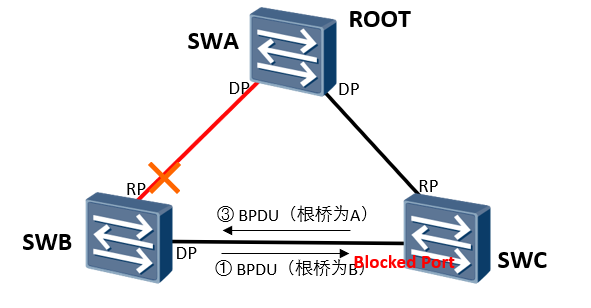
SWB sends out BPDU with itself as the root
When the BP port receives the suboptimal BPDU, it does not process it and waits for the aging timeout of the better BPDU cached by the port (20s)
After the BPDU of the port cache times out, it will enter convergence again and enter the forwarding state (30s) after waiting for 2 Forward Delay times
In STP, the sub optimal BPDU received by other ports of the switch except the specified port will not be processed
4. Scenario where the switch running STP is connected to the user terminal
It takes 30s-50s for the link connecting the terminal of the terminal switch to enter forwarding
In fact, as long as the terminal equipment connected under the port is guaranteed, there will be no loop, that is, it is not necessary to calculate STP and wait for timer timeout
In STP, the link connecting the terminal also needs spanning tree calculation, and the link needs to wait two Forward Delay times to enter forwarding
5. Topology change mechanism of STP
First, the change point sends a TCN message to the root bridge, and the upstream switch receiving the message will reply to the TCA message for confirmation; Finally, after the TCN message reaches the root bridge, the root bridge sends a TC message to inform the device to delete the bridge MAC address table entry. The mechanism is complex and inefficient.
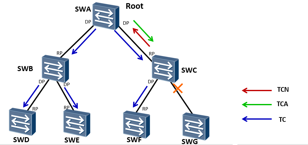
Topology change process:
After the network topology changes, the downstream device will continuously send data to the upstream device TCN BPDU Message.
The upstream equipment receives the information from the downstream equipment TCN BPDU After the message, only the designated port can process it TCN BPDU Message. Other ports may also receive TCN BPDU Message, but it will not be processed.
Upstream equipment will configure BPDU In the message Flags of TCA Bit is set to 1, and then sent to the downstream device to tell the downstream device to stop sending TCN BPDU Message.
One copy of upstream equipment TCN BPDU The message is sent to the root bridge.
Repeat the above steps until the root bridge is received TCN BPDU Message.
Root bridge handle configuration BPDU In the message Flags of TC Send after position 1, and notify the downstream equipment to directly delete the bridge MAC Address table entry.
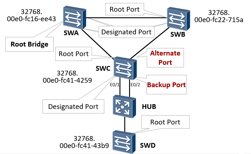
6. Other shortcomings of STP - port role
After the RP port of SWC is down, it needs to be re elected from the other three ports and wait for the timer to timeout before entering forwarding
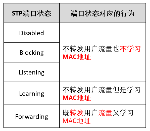
7. Other shortcomings of STP - port status
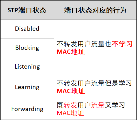
It can be seen from the above figure that for the three port States of Disable, Blocking and Listening, the corresponding behaviors of the three port states are the same from the perspective of user use, but they show different states, which increases the difficulty of use. That is, the port state is somewhat repeated, and the forwarding delay is increased.
2, Improvement of STP by RSTP
Re division of port roles
RSTP defines two new port roles: Backup Port and Alternate Port. They are used for backup. They are also blocked in essence (non block state). The blocked port is removed. Port switching does not need to experience waiting forwarding delay, which is equivalent to STP's uplink fast.
From the perspective of user traffic, Alternate Port Provides another acyclic reachable path from the specified bridge to the root bridge as an alternative to the root port
 From the perspective of user traffic, Backup Port As the backup of the specified port, another acyclic backup path from the root node to the leaf node is provided
According to the shortcomings of STP, RSTP adds two new port roles, and decouples the port attributes fully according to the state and role, so that the port can be described more accurately, which makes the protocol state easier and accelerates the topology convergence. Through the addition of port roles, the understanding and deployment of spanning tree protocol are simplified.
From the perspective of configuring BPDU message sending:
Alternate Port This is due to learning the configuration sent by other bridges BPDU A port blocked by messages.
Backup Port Because I learned the configuration I sent BPDU A port blocked by messages.
From the perspective of user traffic:
Alternate Port Another switchable path from the specified bridge to the root is provided as the backup port of the root port.
Backup Port As the backup of the specified port, it provides another backup path from the root node to the leaf node.
Give one RSTP The process of assigning roles to all ports in the domain is the process of topology convergence.
Reclassification of port status
The state specification of RSTP reduces the original five states to three:
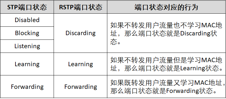
From the user's point of view, there is no difference between Listening, Learning and Blocking status. They also do not forward user traffic.
Aiming at problem 1 - P/A mechanism
Basic principle of P/A mechanism:
 Let A designated port enter the forwarding state as soon as possible and avoid the sending of loop. The message formats include P message, A message and SYNC message.
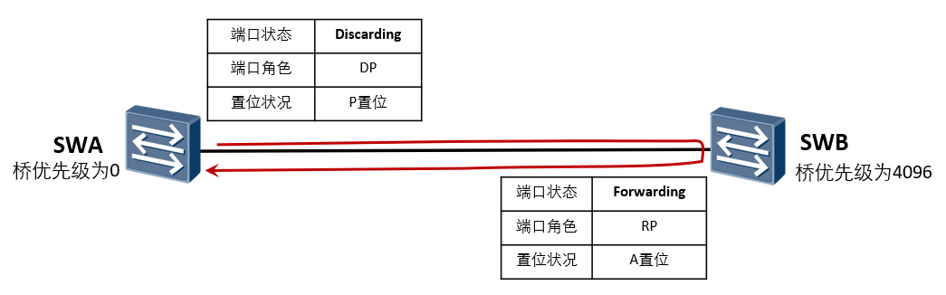
SWA send out P Set BPDU
 Synchronous variables (blocking ports other than edge ports to prevent loops)
SWB send out A Set BPDU
SWA Port received A Set BPDU Message, port enters immediately Forwarding
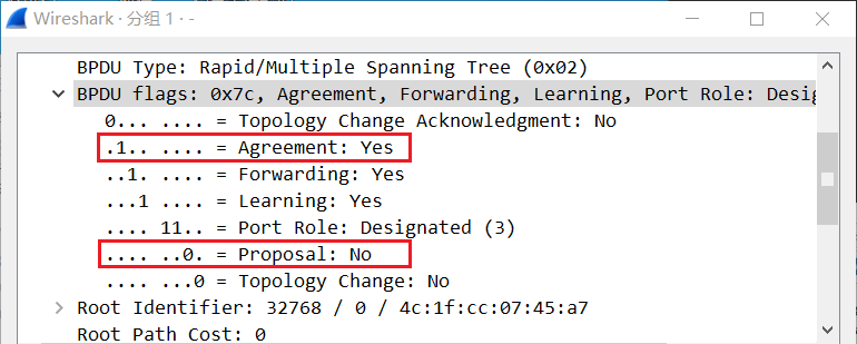
There are Proposal bit and Agreement bit in the flags field of the BPDU. The BPDU sent by the root bridge. When the Proposal bit is 1, it means that the switch thinks it is the root bridge, and then sends the BPDU message with P setting to other switches in the network topology; When other switches with low priority receive this message, they will send A BPDU message with Agreement position bit 1, that is, with A setting.
Characteristics of P/A mechanism
Due to the back and forth confirmation mechanism and synchronous variable mechanism, there is no need to rely on a timer to ensure acyclic. In other words, when comparing priorities between SWA and SWB, only two of them are comparing, and the other ports are blocked, so there is no loop.
Proposal/Agreement Mechanism, whose purpose is to make a specified port enter as soon as possible Forwarding Status.
P/A The mechanism requires that the link between two switching devices must be point-to-point full duplex mode. once P/A If the negotiation fails, the selection of the specified port needs to wait for two hours Forward Delay,Negotiation process and STP Same.
In fact, for STP,The selection of specified ports can be completed quickly. The main speed bottleneck is that in order to avoid loops, you must wait long enough to determine the port status of the whole network, that is, you must wait for at least two ports Forward Delay,All ports can be forwarded.
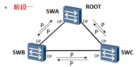
Phase I
The device has just started, RSTP The protocol has just been enabled. All switches think they are root bridges and send messages to other switches P Set BPDU,And send P The port of the message becomes DP At the same time, the interface is in Discarding Status.
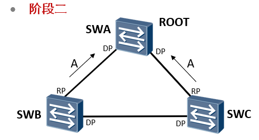
Phase II
Switch SWA received SWB and SWC of P Messages will be ignored because his bridge has the highest priority. Switch SWB and SWC received SWA of P After the news, due to recognition SWA Is the optimal root bridge, according to P/A Negotiation process reply A Message and change the sending port to RP Port, while the interface is in Forwarding Status.
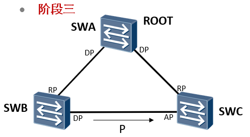
Phase III
SWA And SWB,SWA And SWB of P/A The negotiation has been completed, and the next step is SWB and SWC of P/A Negotiation.
	SWB and SWC Will send the root bridge as SWA of P Send the message to each other.
	 SWC received SWB of P After the message, it is found that P Although the root bridge in the message is the same as that recognized by the sender, the sender's bridge priority is higher than that of the sender(SWB>SWC),All stop sending now P Message, but because there are already ports that are RP Mouth, will not return A News.
	SWB received SWC of P After the message, it is found that P Although the root bridge in the message is the same as that recognized by the sender, the priority of the sender's bridge is lower than that of the sender(SWB>SWC),Will keep sending P News.
	The above status is waiting for 2 months Forward Delay After time, SWB Port is DP Port, at Forwarding Status, SWC Port is AP Port, at Discarding Status.
	actually SWB And SWC Negotiation between is equivalent to returning to STP But it is Discarding Status, which does not affect the forwarding of other services at all.
RSTP election principle is essentially the same as STP: electing root switch - electing root port on non root switch - electing specified port - electing standby port and backup port.
However, RSTP adds the confirmation mechanism of "initiate request reply consent" (P/A mechanism) in the election process. Since there is confirmation in each step, it does not need to rely on the timer to ensure that the network topology is acyclic before forwarding. It only needs to consider the message sent by BPDU and calculate the time of acyclic topology (generally in seconds).
Aiming at problem 2 -- root port fast switching mechanism
When the direct link between SWC and SWA is down, its AP port is switched to RP port and enters the forwarding state, which can complete the convergence in seconds
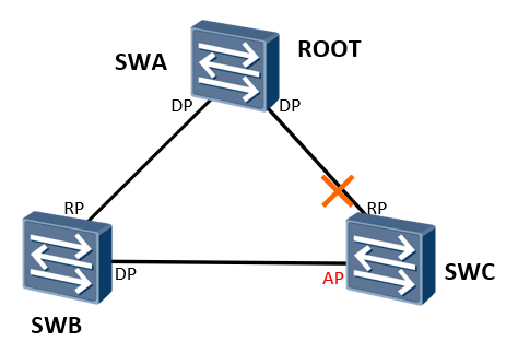
The AP port immediately becomes a new root port and enters the Forwarding state
In order to speed up the convergence time, after the old root port on the device fails, the new root port should immediately migrate to the Forwarding state without ring, and the AP port can enter the Forwarding state immediately considering this demand during the election
Third class BPDU processing mechanism for solving problems
When the direct link between SWB and SWA is down, the AP port of SWC is switched to DP port and enters the forwarding state, which can be completed in seconds
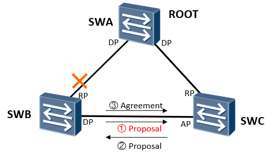
SWB Send out with self as root Proposal Set BPDU
AP Port received suboptimal BPDU The local optimal will be sent immediately after BPDU To the opposite end, and the port role from AP Change to DP
SWB Receive better BPDU,The port role will be redefined immediately DP Port changed to RP Port, and then send Agreement Set BPDU
SWC received Agreement The message will be forwarded immediately
RSTP processes inferior BPDU messages and no longer relies on any timer timeout to solve the topology convergence. Instead, it will immediately send the local optimal BPDU to the opposite end, and then start the P/A mechanism to speed up the topology convergence
Aiming at problem 4 -- introduction of edge port
In RSTP, the link between the switch and the terminal can immediately enter the forwarding state.
It is equivalent to port fast, which can make the edge port not participate in any activity of RSTP. After activation, it will become the forwarding state. If the edge port interface is connected to BPDU, it will lose the attribute of the edge port (equivalent to the BPDU filter of STP).
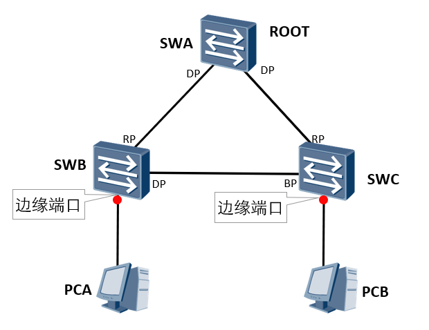
The port connecting the terminal device can be set as an edge port
After the interface connecting the terminal equipment on the switch is set as an edge port, it will immediately enter forwarding. When the port receives BPDU, it will lose the edge port attribute and become a common STP port, and the spanning tree calculation will be carried out again
Aiming at problem 5 -- Optimization of topology change mechanism
The only criterion to judge the topology change: a non edge port is migrated to the Forwarding state.
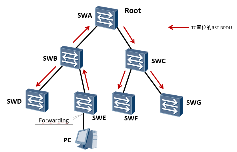
When the network topology changes, the change point switch SWE directly sends the BPDU message with TC set to the whole network, instead of notifying the root bridge first, and then the root bridge sends the TC message to the whole network, which saves the convergence time to a certain extent
Once a change in topology is detected, the following processing will be carried out:
Start one for all non edge specified ports of this switching device TC While Timer,The timer value is Hello Time Twice as much. During this time, it is learned on the port where the emptying state changes MAC Address. At the same time, it is sent out by these ports RST BPDU,among TC Set. once TC While Timer Time out, stop sending RST BPDU.
Received by other switching equipment RST BPDU After, clear all ports and learn MAC Address, except received RST BPDU Port for. Then you can also specify ports and root ports for all your non edges to start TC While Timer,Repeat the above process. In this way, there will be problems in the network RST BPDU Flooding.
Summary:
STP: process of level by level notification
RSTP: flat management. All switches of RSTP can send BPDU. In case of topology change, RSTP will notify the upper and lower switches at the first time, clear the CAM form, and TC while timer 2 hello times
STP and RSTP compatibility
RSTP protocol is fully compatible with STP protocol and downward compatible.
RSTP protocol automatically determines whether the switch connected to it supports STP protocol or RSTP protocol according to the received BPDU version number
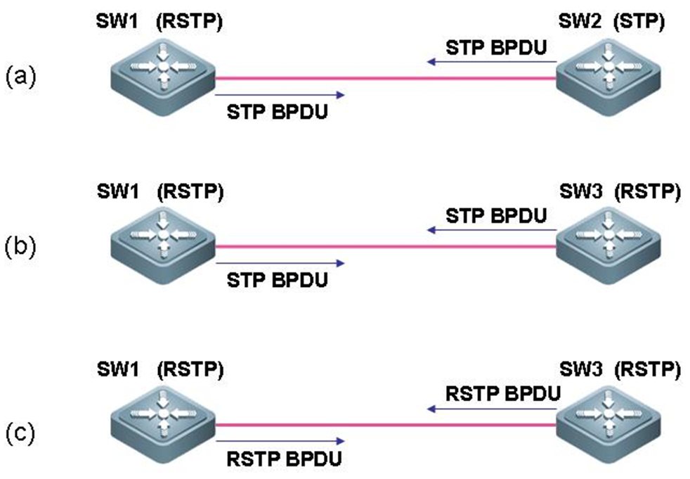
SW1 support RSTP,The message sent is STP message   SW2 Only supported STP The message sent is STP Message, via STP Conduct elections.
SW1 support RSTP,The message sent is STP message   SW3 support RSTP,The message sent is STP Message, via STP Conduct elections.
SW1 support RSTP,The message sent is RSTP message  SW3 support RSTP,The message sent is RSTP Message, via RSTP Conduct elections
Problems caused by topology changes
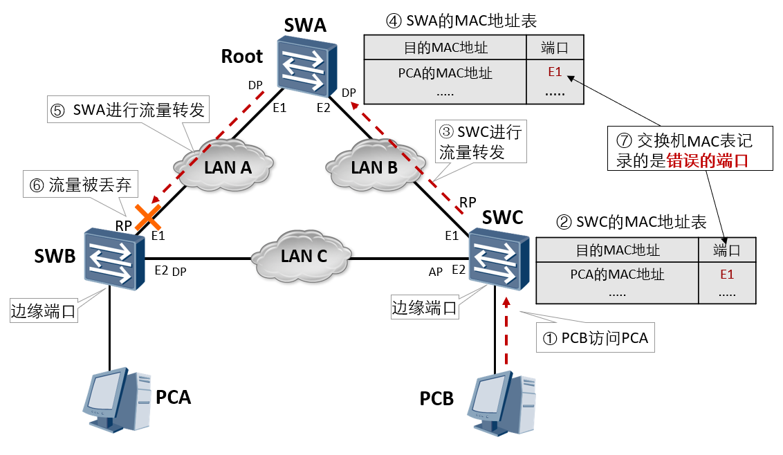
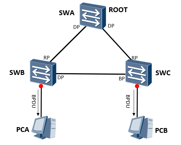
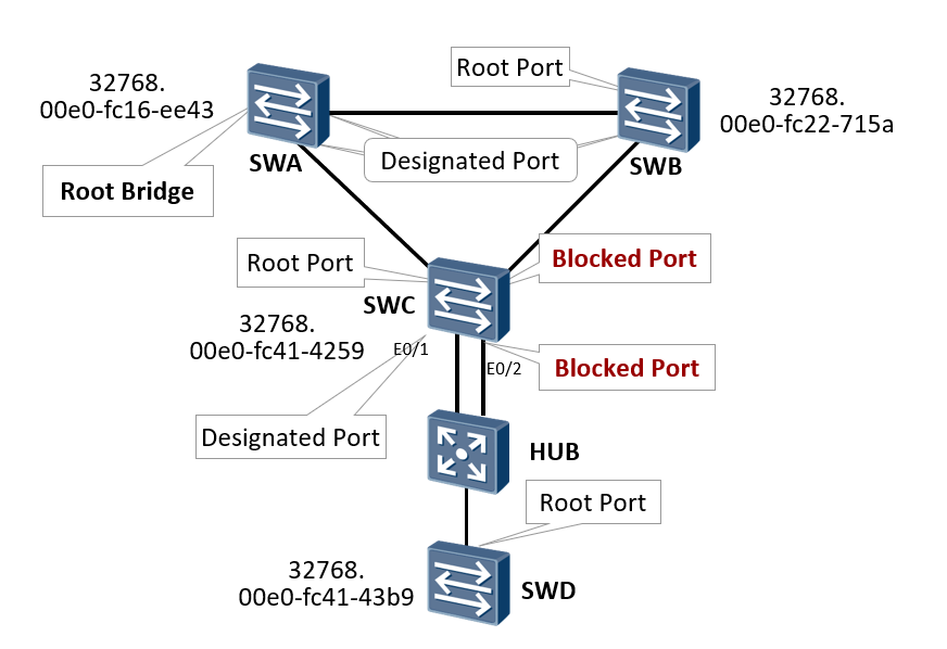
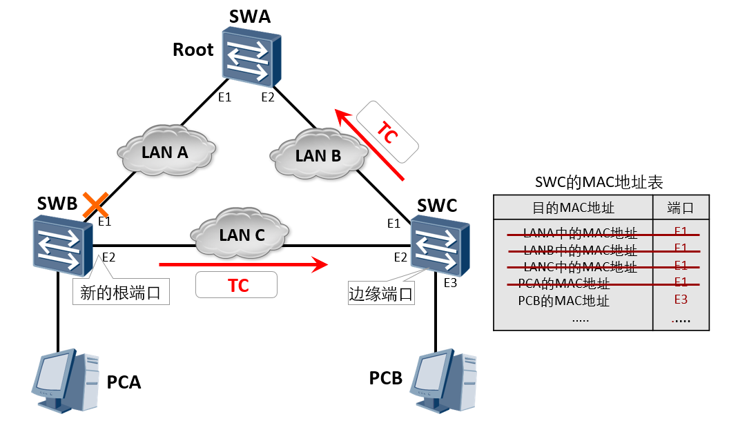
stay RSTP There is only one criterion for detecting whether the topology has changed: a non edge port is migrated to Forwarding Status.
The change of network topology may lead to the failure of the switch MAC An error occurred in the address table.
As shown in the figure, under stable conditions, SWC of MAC Corresponding in the address table PCA of MAC The port of the address is E1. If SWB of E1 The port has failed and SWC of MAC Address table and PCA of MAC The port corresponding to the address is still E1,It will lead to the loss of data forwarding.
Topology change processing (1)
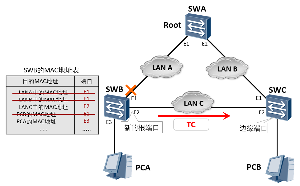
Once a topology change is detected, the following processing will be carried out first:
	Learned on the port whose status has changed MAC Address.
	At the same time, it is sent out by these ports RST BPDU,among TC Set. once TC While Timer Time out, stop sending RST BPDU.
As shown in the figure, SWB of E1 After the port fails, RSTP The treatment process is as follows:
	SWB Recalculate spanning tree, election E2 For the new root port.
	SWB delete MAC Address table E1 The table entry corresponding to the port.
	After the spanning tree recalculation is completed (the port that needs to enter the forwarding state has entered the forwarding state), SWB All non edge ports of send out TC Set RST BPDU.
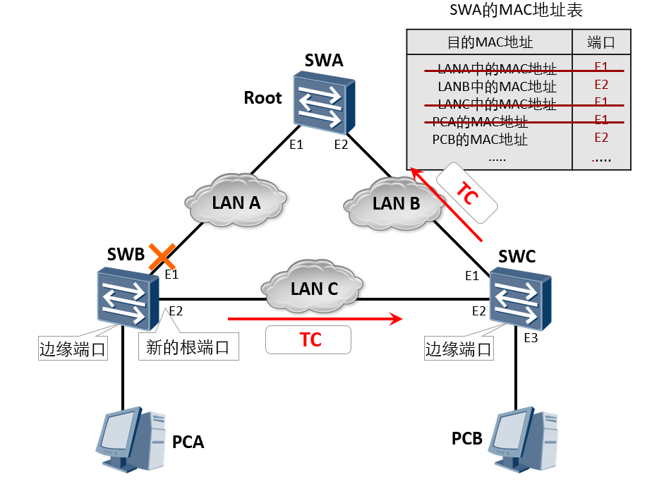
Topology change processing (2)
After receiving the BPDU set by TC, the switching device SWC will clear the MAC address learned by all other non edge ports except the received message
Topology change processing (3)
 Topology change processing (4)
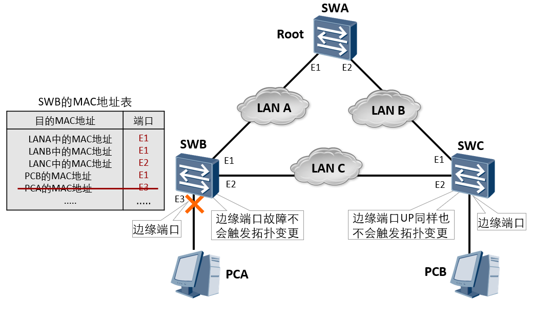
The topology change will not be triggered when the edge port is down, and the topology change will not be triggered after fault recovery.
BPDU protection (1)
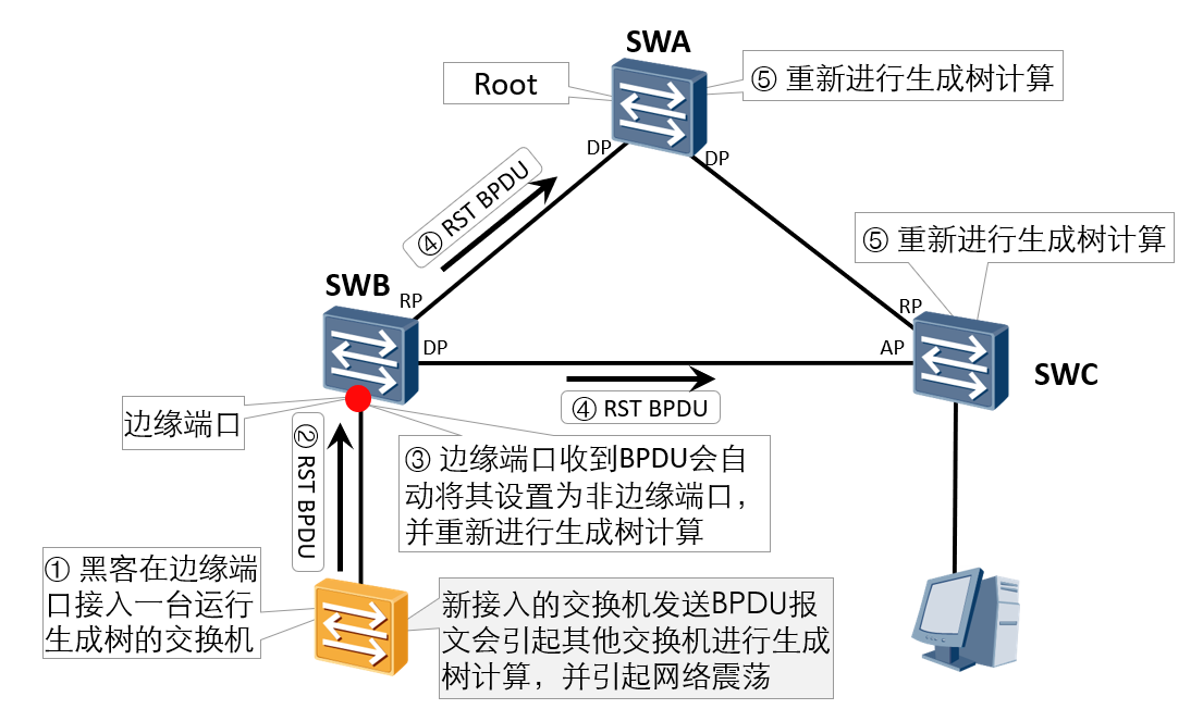
Application scenario
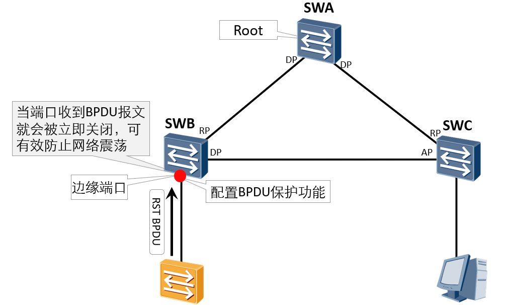
Prevent someone from forging RST BPDU to maliciously attack the switching device. When the edge port receives the message, it will be automatically set as a non edge port and perform spanning tree calculation again, causing network shock.
Implementation principle
After configuring the BPDU protection function, if the edge port receives the BPDU message, the edge port will be closed immediately.
Purpose of configuring edge ports
It is hoped that these ports will be connected to terminal devices when networking in the future; Even if the edge port is connected to the switch, it is necessary to debug the BPDU parameters (BID, port cost value) of the switch first. When the switch is connected to the network, even if there is STP calculation, it will not cause network oscillation again; If the edge ports are not allowed to connect to the switch, configure BPDU protection on these ports.
BPDU protection (2)
Implementation principle: after configuring the BPDU protection function, if the edge port receives the BPDU message, the edge port will be closed immediately.
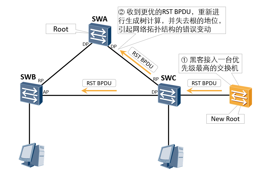
Application scenario: due to the wrong configuration of maintenance personnel or malicious attacks in the network, the legitimate root bridge in the network may receive RST BPDU with higher priority, making the legitimate root bridge lose its root status, resulting in wrong changes in the network topology.
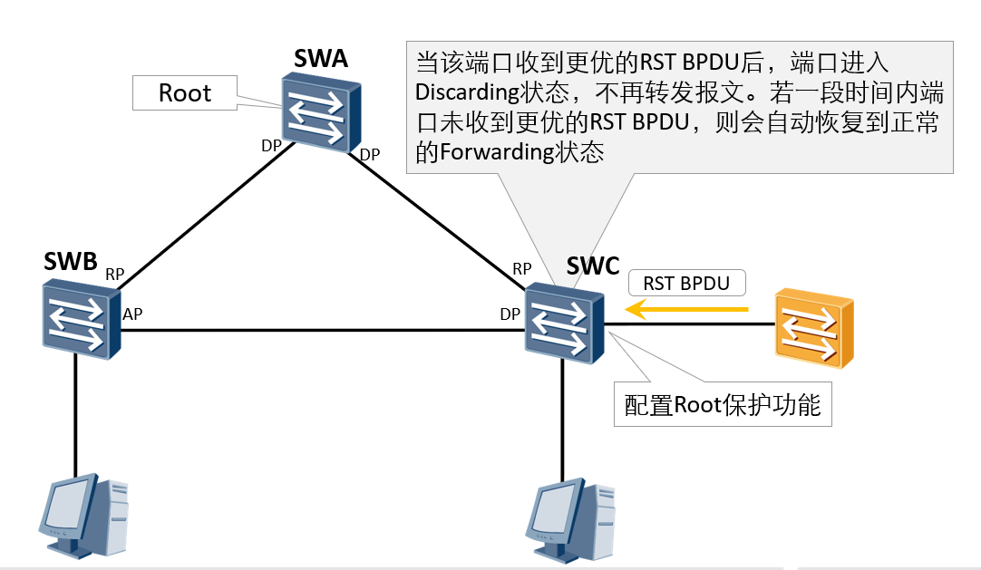
Implementation principle: once the designated port with Root protection function enabled receives RST BPDU with higher priority, the port state will enter the Discarding state and no longer forward messages. After a period of time, if the port does not receive RST BPDU with higher priority, the port will automatically return to the normal Forwarding state.
The Root protection function can only be configured and effective on the specified port.
Root protection (2)
Application scenario: due to the wrong configuration of maintenance personnel or malicious attacks in the network, the legitimate root bridge in the network may receive RST BPDU with higher priority, making the legitimate root bridge lose its root status, resulting in wrong changes in the network topology.
Implementation principle: once the designated port with Root protection function enabled receives RST BPDU with higher priority, the port state will enter the Discarding state and no longer forward messages. After a period of time, if the port does not receive RST BPDU with higher priority, the port will automatically return to the normal Forwarding state.
The Root protection function can only be configured and effective on the specified port.
TC-BPDU flood protection (1)
000 [external chain picture transfer failed. The source station may have anti-theft chain mechanism. It is recommended to save the picture and upload it directly (img-xox8pbvu-1617278409092)( https://img-0blog.csdnimg.cn/20210401165514686.png?x -oss-process=image/watermark,type_ ZmFuZ3poZW5naGVpdGk,shadow_ 10,text_ aHR0cHM6Ly9ibG9nLmNzZG4ubmV0L20wXzUzOTU0MjEy,size_ 16,color_ FFFFFF,t_ 70)]
TC-BPDU attack:
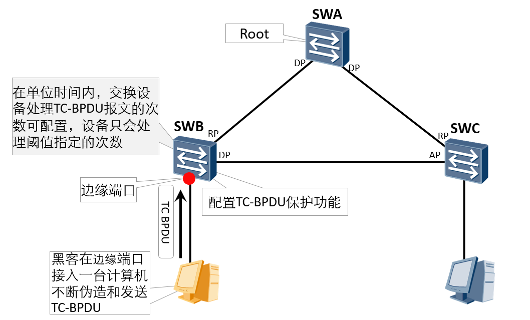
After receiving the TC-BPDU message, the switch will delete the MAC address table entry. If someone forges TC-BPDU messages to maliciously attack the switch, the switch will receive a lot of TC-BPDU messages in a short time. Frequent deletion operations will cause a great burden on the equipment and bring great hidden dangers to the stability of the network.
TC-BPDU flood protection (2)
TC-BPDU attack protection:
After the anti TC-BPDU message attack function is enabled, the number of times RSTP process processes TC type BPDU messages in unit time can be configured (the default unit time is 2 seconds and the default processing times is 3). If the number of TC type BPDU messages received by the RSTP process in unit time is greater than the configured threshold, the RSTP process will only process the times specified by the threshold; For other TC type BPDU messages exceeding the threshold, after the timer expires, the RSTP process only processes them uniformly once. This can avoid frequent deletion of MAC address table entries, so as to protect the switch.
RSTP configuration requirements
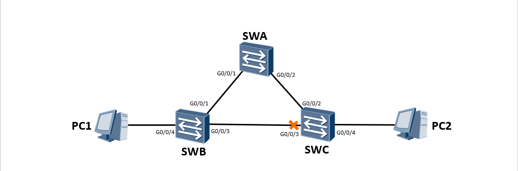
As shown in the figure, SWA, SWB and SWC form a ring switching network. In order to eliminate the impact of the loop on the network, make the switches run RSTP, and finally trim the ring network structure into a tree network structure without loop.
RSTP configuration implementation
SWA
stp enable  //Global open STP
stp mode rstp  //Configure STP mode to RSTP
stp root primary //Configure SWA as root bridge
SWB
stp enable
stp mode rstp
stp bpdu-protection  //Turn on BPDU protection globally and use it together with edge ports
interface GigabitEthernet 0/0/4
stp edged-port enable  //Configure port as edge port
SWC
stp enable
stp mode rstp
stp bpdu-protection
interface GigabitEthernet 0/0/4
stp edged-port enable
Viewing spanning tree information on SWA
<SWA>display stp brief
MSTID  Port                        Role  STP State     Protection
0    GigabitEthernet0/0/1        DESI  FORWARDING      NONE
0    GigabitEthernet0/0/2        DESI  FORWARDING      NONE


<SWA>display stp
-------[CIST Global Info][Mode RSTP]-------
CIST Bridge         :0    .4c1f-cc5f-55e4
Config Times        :Hello 2s MaxAge 20s FwDly 15s MaxHop 20
Active Times        :Hello 2s MaxAge 20s FwDly 15s MaxHop 20
CIST Root/ERPC      :0    .4c1f-cc5f-55e4 / 0
CIST RegRoot/IRPC   :0    .4c1f-cc5f-55e4 / 0
CIST RootPortId     :0.0
BPDU-Protection     :Disabled
CIST Root Type      :Primary root
View spanning tree information on SWB
[SWB]display stp brief
MSTID  Port                        Role  STP State     Protection
0    GigabitEthernet0/0/1        ROOT  FORWARDING      NONE
0    GigabitEthernet0/0/3        DESI  FORWARDING      NONE
0    GigabitEthernet0/0/4        DESI  FORWARDING      BPDU
View spanning tree information on SWC
<SWC>display stp brief
 MSTID  Port                        Role  STP State     Protection
0    GigabitEthernet0/0/2        ROOT  FORWARDING      NONE
0    GigabitEthernet0/0/3        ALTE  DISCARDING      NONE
0    GigabitEthernet0/0/4        DESI  FORWARDING      BPDU
Finally, the G0/0/3 interface of SWC is blocked and the loop in the network is eliminated