The timer configuration of 6747 is as follows:
1. Set the pin multiplexing register PINMUX8 and select the three-pin function as the timer output. Note that the pin coincides with the SCL of I2C0.
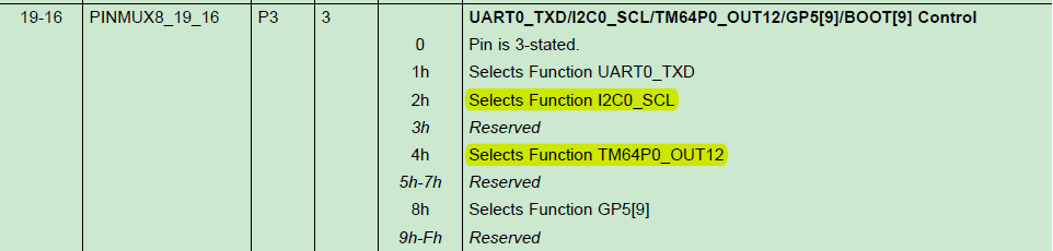
(User Manual P203)
2. Set the timer setup_TIMER0(); clear the high 32-bit counter TIMER34 and the low 32-bit counter TIMER12 of TIMER0 in the setup_TIMER0 function, then select the 32-bit unchained mode, the pre-dividing coefficient is 1, and set the cycle number register as the periodic value.
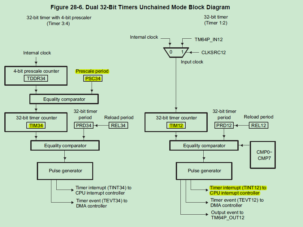
(User Manual P1235)
3. In the interrupt multiplexing register INTmux1, select the interrupt source of CPU level interrupt and set the interrupt source of CPU interrupt as a timer.

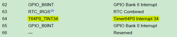
(User Manual P72)
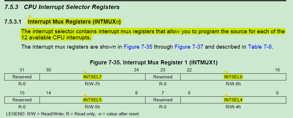
(MegaModule Manual P178)
4. Set ISTP as the address of the interrupt vector table and point ISTP to the interrupt vector table
5. Clear all interruption signs
6. Enables unshieldable interrupt bits and turns on interrupt master switch GIE bits
7. Enable 12 and 34 parts of timer 0 to select continuous mode, and, if TIMER 1 is not used, be sure to disable TIMER 1
8. Write interrupt service subroutine, so that the program can execute interrupt service program on time.
Note: When 6747 64-bit timer is used as 32-bit unchained mode, it is divided into two parts: Timer 12 and Timer 34. When initializing TIMER_TCR, do not turn it on. Otherwise, it will affect interruption. The specific reason is that this part is opened, but there is no corresponding interrupt process. Sequence, when interruption occurs, can not be correctly handled, resulting in the other part of the 32-bit timer interruption after the first interruption can no longer enter the interrupt program, this must be noted that the unused TIMER part must not be opened!!!
Attach a timer program (the commentary code is written in the RCSL library, not needed):
/*
 *  Core 6747 'led program.
 *  All by yanxu.
 */

#include "stdio.h"
#include "C6747.h"

//const unsigned int TIMER_PERIOD = 0x00001000;
const unsigned int TIMER_PERIOD = 0x00B71B00;

static void setup_TIMER0(void);
static void test_TIMERS(void);

void myExit(int);
void test_TIMERS(void);

void TIMER0_TINT12_isr();

static int TIMER0_TINT12_status = 1;          // Pass/Fail flag
static int test_status = 1;                   // Test status
unsigned int k=0;

extern const unsigned int TIMER_PERIOD;

/*============================================================================*/
/*                        EXTERNAL FUNCTION PROTOTYPES                        */
/*============================================================================*/

extern void vectors(void);

void delay()
{
 Uint32 i;
 for(i=0;i<0x1fffff;i++);

}

void main( void )
{
/*Initialization 6747 Core*/
 C6747_init();
 PINMUX11=0X08888888;
 PINMUX8=0x00040000;
 GPIO_DIR23=0;//Set IO as output to control LED
 //GPIO_DIR23=0xffffffff;

/* for(;;)
 {GPIO_OUT_DATA23=0x800;//GPIO Output high level
  delay(); //delayed
  GPIO_OUT_DATA23=0x0;//GPIO Output low level
  delay();  //delayed
    }*/

 /* Configure TIMER0, both halves to be used by application                */
     setup_TIMER0();
 /* function to test the timer interrupts                                  */
     test_TIMERS();
/*     for(;;)
      {
     	GPIO_OUT_DATA23=0x800;//GPIO Output high level
     	delay(); //delayed
     	GPIO_OUT_DATA23=0x0;//GPIO Output low level
     	delay();  //delayed
      }*/
     while(1)
     {

     }
}
void setup_TIMER0 (void)
{
    /* Clear TIM12 register                        */
//    CSL_FINST(tmr0Regs->TIM12,TMR_TIM12_TIM12,RESETVAL);
	TIMER0_TIM12=0x0;

    /* Clear TIM34 register                        */
//    CSL_FINST(tmr0Regs->TIM34,TMR_TIM34_TIM34,RESETVAL);
	TIMER0_TIM34=0x0;

    /* Select 32 bit unchained mode                */
    /* Take the timer out of reset and set the pre-scalar count for 3:4       */
/*    tmr0Regs->TGCR = CSL_FMKT(TMR_TGCR_TIMMODE,32BIT_UNCHAIN)
                     | CSL_FMKT(TMR_TGCR_TIM12RS,NO_RESET)
                     | CSL_FMKT(TMR_TGCR_TIM34RS,NO_RESET)
                     | CSL_FMK(TMR_TGCR_PSC34,0x1);*/
	TIMER0_TGCR=0x00000107;

    /* Set timer0 PRD1:2                           */
//    CSL_FINS(tmr0Regs->PRD12,TMR_PRD12_PRD12,TIMER_PERIOD);
	TIMER0_PRD12=TIMER_PERIOD;

    /* Set timer0 PRD3:4                           */
/*    CSL_FINS(tmr0Regs->PRD34,TMR_PRD34_PRD34,TIMER_PERIOD);
	TIMER0_PRD34=TIMER_PERIOD;*/
}

static void test_TIMERS(void)
{
    /* Interrupt Controller Register Overlay                                  */

    printf("Testing TIMER0 and TIMER1 in unchained 32 bit mode.\n");
    printf("Starting TIMER0 3:4 side and TIMER1 1:2 and 3:4 sides.\n");

    /* connect the event to the interrupt 4,5,6 and 7                         */
/*    CSL_FINS(intcRegs->INTMUX1, INTC_INTMUX1_INTSEL4,TIMER_EVENT0);
    CSL_FINS(intcRegs->INTMUX1, INTC_INTMUX1_INTSEL5,TIMER_EVENT1);
    CSL_FINS(intcRegs->INTMUX1, INTC_INTMUX1_INTSEL6,TIMER_EVENT2);
    CSL_FINS(intcRegs->INTMUX1, INTC_INTMUX1_INTSEL7,TIMER_EVENT3);*/
    INTmux1=0x30284004;

    /* set ISTP to point to the vector table address                          */
    ISTP = (unsigned int)vectors;

    /* clear all interrupts, bits 4 thru 15                                   */
    ICR = 0xFFF0;

    /* enable the bits for non maskable interrupt and                         */
    IER = 0xF2;

    /* enable interrupts, set GIE bit                                         */
    _enable_interrupts();

    delay();

    /* Enable TIMER0 1:2 side, one shot mode                                  */
 /*   CSL_FINST(tmr0Regs->TCR,TMR_TCR_ENAMODE12,EN_ONCE);
    TIMER0_TRC=0x00400040;*/

    /* Enable TIMER0 1:2 side, continuous mode                                  */
    TIMER0_TRC=0x00000080;

    /* Enable TIMER0 3:4 side, one shot mode                                  */
/*    CSL_FINST(tmr0Regs->TCR,TMR_TCR_ENAMODE34,EN_ONCE);*/

    /* Enable TIMER1 1:2 side, one shot mode                                  */
/*    CSL_FINST(tmr1Regs->TCR,TMR_TCR_ENAMODE12,EN_ONCE);*/
    TIMER1_TRC=0x00000000;

    /* Enable TIMER1 3:4 side, one shot mode                                  */
/*    CSL_FINST(tmr1Regs->TCR,TMR_TCR_ENAMODE34,EN_ONCE);*/

    /* Sleep for 3 system clock PRD's to ensure other timers have ran.        *
     * Since 3:4 sides are running at a divide by 2 PRD, we need to           *
     * sleep at least 2 PRDs.                                                 */
    delay();

    do
    {
        /* Check if interrupts occurred       */
        test_status = TIMER0_TINT12_status;
        delay();
    }while (test_status != 0);

    /* Call exit function                     */
    myExit(test_status);
}

interrupt void TIMER0_TINT12_isr()
{
    /* Disable TIMER0 1:2 side                */
/*    CSL_FINST(tmr0Regs->TCR,TMR_TCR_ENAMODE12,DISABLE);
	TIMER0_TRC=0x00000000;*/

    /* Set flag to 0 indicating ISR occurred  */
    TIMER0_TINT12_status=0;

    k=(k+1)%2;
    if(k==0)
    {
    	GPIO_OUT_DATA23=0x800;//GPIO Output High Level
    }
    else
    {
    	GPIO_OUT_DATA23=0x0;//GPIO Output Low Level
    }

}

void myExit(int test_result)
{
    /* Disable TIMER0 1:2 side  */
/*    CSL_FINST(tmr0Regs->TCR,TMR_TCR_ENAMODE12,DISABLE);
	TIMER0_TRC=0x00000000;*/

    /* Disable TIMER0 3:4 side  */
/*    CSL_FINST(tmr0Regs->TCR,TMR_TCR_ENAMODE34,DISABLE);*/

    /* Disable TIMER1 1:2 side  */
/*    CSL_FINST(tmr1Regs->TCR,TMR_TCR_ENAMODE12,DISABLE);*/
/*	TIMER1_TRC=0x00000000;*/

    /* Disable TIMER1 3:4 side  */
/*    CSL_FINST(tmr1Regs->TCR,TMR_TCR_ENAMODE34,DISABLE);*/

    /* Turn off all interrupts  */
/*    _disable_interrupts();*/

    /* Display test status      */
    if (test_result == 0)
    {
        printf("Timer0 and Timer1 interrupt test: PASSED.\n");
    }
    else
    {
        printf("Timer0 and Timer1 interrupt test: FAILED.\n");
    }
}