In the previous section, we built templates and created single tasks. In this section, we build multi tasks
uCOSIII system transplantation (I) construction of single task
Task requirements: build three tasks (two LED s and one BUZ)
Refer to the transplantation of wildfire. (my board is different from wildfire, so I need to make some changes)
schematic diagram:
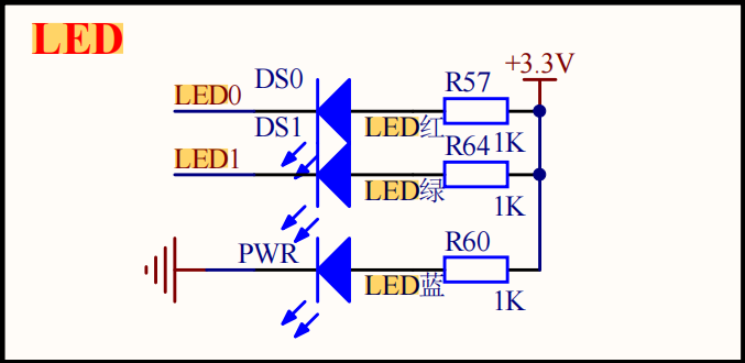
The lowest blue light is the power indicator, and LED0 and LED1 are lit at low level according to the schematic diagram (so we should set the corresponding pins of these two LEDs to high level during initialization)
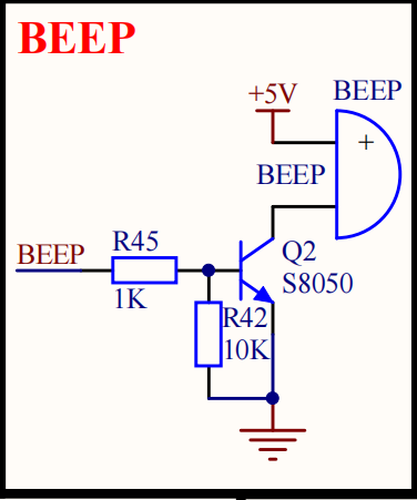
BEEP we set the initialization to low level (high level operation) according to the schematic diagram
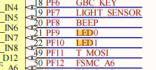
Corresponding pin relationship
PF8—BUZ
PF9—LED0
PF10—LED1
LED.C
void LED_GPIO_Config(void)
{
	GPIO_InitTypeDef GPIO_InitStructure;
    RCC_AHB1PeriphClockCmd ( LED1_GPIO_CLK| LED2_GPIO_CLK| BUZ_GPIO_CLK, ENABLE);
    GPIO_InitStructure.GPIO_Pin = LED1_PIN;
    GPIO_InitStructure.GPIO_Mode = GPIO_Mode_OUT;
    GPIO_InitStructure.GPIO_OType = GPIO_OType_PP;
    GPIO_InitStructure.GPIO_PuPd = GPIO_PuPd_UP;
    GPIO_InitStructure.GPIO_Speed = GPIO_Speed_2MHz;
    GPIO_Init(LED1_GPIO_PORT, &GPIO_InitStructure);
    GPIO_InitStructure.GPIO_Pin = LED2_PIN;
    GPIO_Init(LED2_GPIO_PORT, &GPIO_InitStructure);
    GPIO_InitStructure.GPIO_Pin = BUZ_PIN;
    GPIO_Init(BUZ_GPIO_PORT, &GPIO_InitStructure);
	LED_MODE3;	//This is for Macro definition in h file / * turn off LED1/LED2 light*/
}
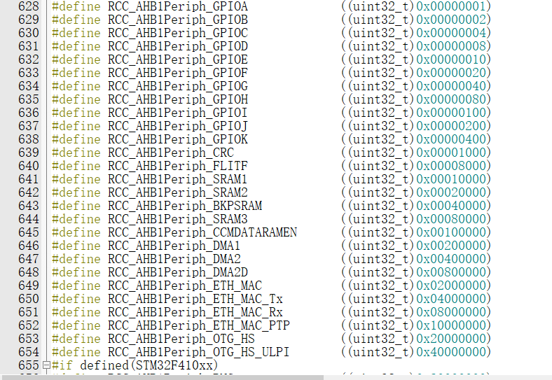
F407 clock mount
For F407 series boards, it can be seen that most of the IO ports are on the AHB1 bus, so the clock is used to write RCC directly when initializing peripherals (most of them need special attention)_ AHB1PeriphClockCmd
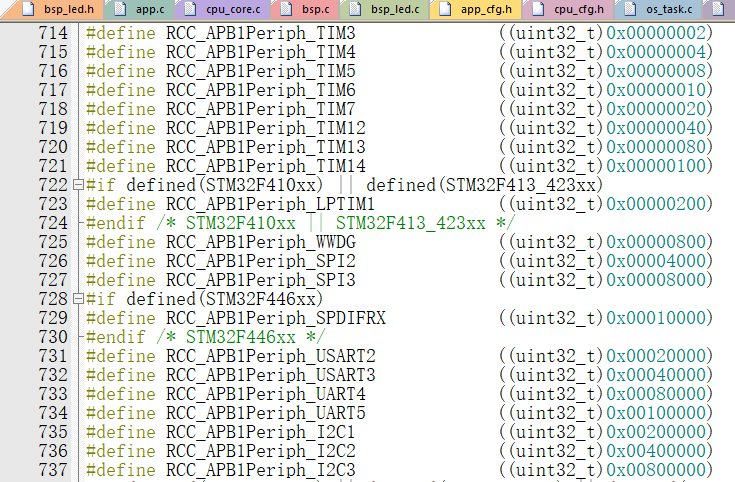
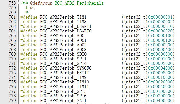
When using timer (TIM), serial port (UART) and SPI (as shown in the following two figures), you can see that APB1 or APB2 clock is used
It can be seen that three I2C of F407 are all on APB1 clock bus and four ADC s are all on APB2 clock bus
LED. H (macro definition madness)
#ifndef __LED_H
#define	__LED_H

#include "stm32f4xx.h"

//Pin definition
/*******************************************************/
//LED1
#define LED1_PIN                  GPIO_Pin_9
#define LED1_GPIO_PORT            GPIOF
#define LED1_GPIO_CLK             RCC_AHB1Periph_GPIOF

//LED2
#define LED2_PIN                  GPIO_Pin_10
#define LED2_GPIO_PORT            GPIOF
#define LED2_GPIO_CLK             RCC_AHB1Periph_GPIOF

//BUZ
#define BUZ_PIN                  GPIO_Pin_8
#define BUZ_GPIO_PORT            GPIOF
#define BUZ_GPIO_CLK             RCC_AHB1Periph_GPIOF
/************************************************************/


/** Macro to control the LED light on and off,
	* LED Low level on, set ON=0, OFF=1
	* If the LED high level is on, set the macro to ON=1 and OFF=0
	*/
#define ON  0
#define OFF 1

/* Macros with parameters can be used like inline functions */
#define LED1(a)	if (a)	\
					GPIO_SetBits(LED1_GPIO_PORT,LED1_PIN);\
					else		\
					GPIO_ResetBits(LED1_GPIO_PORT,LED1_PIN)

#define LED2(a)	if (a)	\
					GPIO_SetBits(LED2_GPIO_PORT,LED2_PIN);\
					else		\
					GPIO_ResetBits(LED2_GPIO_PORT,LED2_PIN)


#define BUZ(a)	if (a)	\
					GPIO_SetBits(BUZ_GPIO_PORT,BUZ_PIN);\
					else		\
					GPIO_ResetBits(BUZ_GPIO_PORT,BUZ_PIN)

/* The method of directly operating registers controls IO */
#define 	 digitalHi(p,i) 			  {p->BSRRL=i;} 		// Set to high level
#define digitalLo(p,i) 			  {p->BSRRH=i;} 		// Output low level
#define digitalToggle(p,i) 	 	  {p->ODR ^=i;} 		// Output reversal state

/* Define macros that control IO */
#define LED1_TOGGLE 		 digitalToggle(LED1_GPIO_PORT,LED1_PIN) / / Flip
#define LED1_OFF			digitalHi(LED1_GPIO_PORT,LED1_PIN)
#define LED1_ON				digitalLo(LED1_GPIO_PORT,LED1_PIN)

#define LED2_TOGGLE		digitalToggle(LED2_GPIO_PORT,LED2_PIN)
#define LED2_OFF			digitalHi(LED2_GPIO_PORT,LED2_PIN)
#define LED2_ON				digitalLo(LED2_GPIO_PORT,LED2_PIN)

#define BUZ_TOGGLE		digitalToggle(BUZ_GPIO_PORT,BUZ_PIN)
#define BUZ_ON 			   digitalHi(BUZ_GPIO_PORT,BUZ_PIN) / / buzzer high level on
#define BUZ_OFF 				 digitalLo(BUZ_GPIO_PORT,BUZ_PIN) / / low level shutdown


//LED1 on LED2 off
#define LED_MODE1  \
					LED1_ON;\
					LED2_OFF;\


//LED1 off LED2 on
#define LED_MODE2		\
					LED1_OFF;\
					LED2_ON;\


//LED1 and LED2 are closed
#define LED_MODE3	\
					LED1_OFF;\
					LED2_OFF;\


//LED1 and LED2 are on
#define LED_MODE4	\
					LED1_OFF;\
					LED2_OFF;\


void LED_GPIO_Config(void);

#endif /* __LED_H */
You can see many macro definitions here. Most of them are changed directly after transplantation The macro in the file is OK, as mentioned in the previous section.
//LED1
#define LED1_PIN                  GPIO_Pin_9
#define LED1_GPIO_PORT            GPIOF
#define LED1_GPIO_CLK             RCC_AHB1Periph_GPIOF

//LED2
#define LED2_PIN                  GPIO_Pin_10
#define LED2_GPIO_PORT            GPIOF
#define LED2_GPIO_CLK             RCC_AHB1Periph_GPIOF

//BUZ
#define BUZ_PIN                  GPIO_Pin_8
#define BUZ_GPIO_PORT            GPIOF
#define BUZ_GPIO_CLK             RCC_AHB1Periph_GPIOF
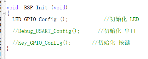
The next step is to add the initialization function to
BSP.C
In this function, all initialization functions will be put here in the future (specification)
APP.C
#include <includes.h>

/*============Task control block==============*/
static  OS_TCB   AppTaskStartTCB;

static  OS_TCB   AppTaskLed1TCB;
static  OS_TCB   AppTaskLed2TCB;
static  OS_TCB   AppTaskbuz3TCB;


/*======================Task stack size=====================*/
static  CPU_STK  AppTaskStartStk[APP_TASK_START_STK_SIZE];

static  CPU_STK  AppTaskLed1Stk [ APP_TASK_LED1_STK_SIZE ];
static  CPU_STK  AppTaskLed2Stk [ APP_TASK_LED2_STK_SIZE ];
static  CPU_STK  AppTaskBUZStk  [ APP_TASK_BUZ3_STK_SIZE ];

/*=====================Function declaration======================*/
static  void  APPTaskStart  (void *p_arg);

static  void  AppTaskLed1  ( void * p_arg );
static  void  AppTaskLed2  ( void * p_arg );
static  void  AppTaskBUZ3  ( void * p_arg );


int  main (void)
{
    OS_ERR  err;


    OSInit(&err);                                               /* Init uC/OS-III.                                      */

    OSTaskCreate((OS_TCB     *)&AppTaskStartTCB,                /* Create the start task   Task control block                                  */
                 (CPU_CHAR   *)"App Task Start",                /*         Task name                                                   */
                 (OS_TASK_PTR ) APPTaskStart,                   /*         Task interface                                                  */
                 (void       *) 0,                              /*         Parameters passed to the task function                                      */
                 (OS_PRIO     ) APP_TASK_START_PRIO,            /*         Task priority                                                */
                 (CPU_STK    *)&AppTaskStartStk[0],             /*         Task stack start address (base address)                                 */
                 (CPU_STK_SIZE) APP_TASK_START_STK_SIZE / 10,   /*         Remaining stack size (task stack depth limit)                            */
                 (CPU_STK_SIZE) APP_TASK_START_STK_SIZE,        /*         Task stack size                                                */
                 (OS_MSG_QTY  ) 5u,                             /*         The maximum number of messages that the task internal message queue can receive. When it is 0, it is forbidden to receive messages       */
                 (OS_TICK     ) 0u,                             /*         The time slice length when the time slice rotation is enabled. When it is 0, it is the default length                */
                 (void       *) 0,                              /*         User supplementary storage                                              */
                 (OS_OPT      )(OS_OPT_TASK_STK_CHK | OS_OPT_TASK_STK_CLR),/*Task options                                                    */
                 (OS_ERR     *)&err);                          /*Store the return value of the function when the error occurs*/

    OSStart(&err);  //Start ucosiii / * start multitasking (i.e. give control to UC / os-iii)*/
	  while(1);

}


static  void  APPTaskStart (void *p_arg)
{
    CPU_INT32U  cpu_clk_freq;
    CPU_INT32U  cnts;
    OS_ERR      err;


   (void)p_arg;
	/*Development board hardware initialization*/
    CPU_Init();
    BSP_Init();                                                 /* Initialize BSP functions                             */

    cpu_clk_freq = BSP_CPU_ClkFreq();                           /* Determine SysTick reference freq.                    */
    cnts = cpu_clk_freq / (CPU_INT32U)OSCfg_TickRate_Hz;        /* Determine nbr SysTick increments                     */
    OS_CPU_SysTickInit(cnts);                                   /* Init uC/OS periodic time src (SysTick).              */
  /*Memory initialization*/
    Mem_Init();                                                 /* Initialize Memory Management Module                  */

#if OS_CFG_STAT_TASK_EN > 0u
    OSStatTaskCPUUsageInit(&err);   //Statistical task / * Compute CPU capacity with no task running*/
#endif


#ifdef  CPU_CFG_INT_DIS_MEAS_EN
  CPU_IntDisMeasMaxCurReset();
#endif

/*==========================================App Task Led1================================================================*/
    OSTaskCreate((OS_TCB     *)&AppTaskLed1TCB,                /* Create the Led1 task                                */
                 (CPU_CHAR   *)"App Task Led1",
                 (OS_TASK_PTR ) AppTaskLed1,
                 (void       *) 0,
                 (OS_PRIO     ) APP_TASK_LED1_PRIO,
                 (CPU_STK    *)&AppTaskLed1Stk[0],
                 (CPU_STK_SIZE) APP_TASK_LED1_STK_SIZE / 10,
                 (CPU_STK_SIZE) APP_TASK_LED1_STK_SIZE,
                 (OS_MSG_QTY  ) 5u,
                 (OS_TICK     ) 0u,
                 (void       *) 0,
                 (OS_OPT      )(OS_OPT_TASK_STK_CHK | OS_OPT_TASK_STK_CLR),
                 (OS_ERR     *)&err);
/*===========================================App Task Led2================================================================*/
    OSTaskCreate((OS_TCB     *)&AppTaskLed2TCB,                /* Create the Led2 task                                */
                 (CPU_CHAR   *)"App Task Led2",
                 (OS_TASK_PTR ) AppTaskLed2,
                 (void       *) 0,
                 (OS_PRIO     ) APP_TASK_LED2_PRIO,
                 (CPU_STK    *)&AppTaskLed2Stk[0],
                 (CPU_STK_SIZE) APP_TASK_LED2_STK_SIZE / 10,
                 (CPU_STK_SIZE) APP_TASK_LED2_STK_SIZE,
                 (OS_MSG_QTY  ) 5u,
                 (OS_TICK     ) 0u,
                 (void       *) 0,
                 (OS_OPT      )(OS_OPT_TASK_STK_CHK | OS_OPT_TASK_STK_CLR),
                 (OS_ERR     *)&err);
/*============================================App Task BUZ3==========================================================*/
    OSTaskCreate((OS_TCB     *)&AppTaskbuz3TCB,                /* Create the BUZ3 task                                */
                 (CPU_CHAR   *)"App Task BUZ3",
                 (OS_TASK_PTR ) AppTaskBUZ3,
                 (void       *) 0,
                 (OS_PRIO     ) APP_TASK_BUZ3_PRIO ,
                 (CPU_STK    *)&AppTaskBUZStk[0],
                 (CPU_STK_SIZE) APP_TASK_BUZ3_STK_SIZE / 10,
                 (CPU_STK_SIZE) APP_TASK_BUZ3_STK_SIZE,
                 (OS_MSG_QTY  ) 5u,
                 (OS_TICK     ) 0u,
                 (void       *) 0,
                 (OS_OPT      )(OS_OPT_TASK_STK_CHK | OS_OPT_TASK_STK_CLR),
                 (OS_ERR     *)&err);


		OSTaskDel ( & AppTaskStartTCB, & err );   //Delete own task


}


/*
*********************************************************************************************************
*                                          LED1 TASK
*********************************************************************************************************
*/

static  void  AppTaskLed1 ( void * p_arg )
{
    OS_ERR      err;

    (void)p_arg;


    while (DEF_TRUE) {                                          /* Task body, always written as an infinite loop.       */
			LED1_TOGGLE;
			OSTimeDly ( 1000, OS_OPT_TIME_DLY, & err );
    }


}


/*
*********************************************************************************************************
*                                          LED2 TASK
*********************************************************************************************************
*/

static  void  AppTaskLed2 ( void * p_arg )
{
    OS_ERR      err;

    (void)p_arg;


    while (DEF_TRUE) {                                          /* Task body, always written as an infinite loop.       */
			LED2_TOGGLE;
			OSTimeDly ( 500, OS_OPT_TIME_DLY, & err );
    }


}


/*
*********************************************************************************************************
*                                          	BUZ TASK
*********************************************************************************************************
*/

static  void  AppTaskBUZ3 ( void * p_arg )
{
    OS_ERR      err;

    (void)p_arg;


    while (DEF_TRUE) {                                          /* Task body, always written as an infinite loop.       */
			//BUZ_TOGGLE;
			BUZ_OFF;

			OSTimeDly ( 500, OS_OPT_TIME_DLY, & err );
    }


}
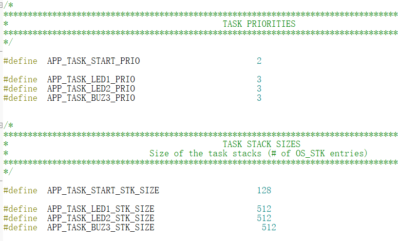
Specify the stack size and priority in app_cfg.h
Here, three separate tasks are constructed, and the general process is as follows
1. Define task control block
2. Define the stack size of each task
3. Create a task first (instructions in the task, stack residue, priority, interface function, etc.)
4. Add three new tasks to the last created task and delete the task itself ostask del() (or suspend)
5. Start the initial creation task
Complete project Download
Select project: 2 UCOS multitasking construction
Author: Jiang Duoduo (student in school)
Copyright reserved. Welcome to reprint with the original link:)
Never forget the original intention, keep the mission in mind, and be inspired to become an excellent embedded siege lion! (my 16th blog)