preface
I remember that when I first started learning stm32, the first program was to turn on the LED light, but at that time, I only knew about the process and did not know the meaning of each line of code, so today I went back to take notes and understand each line of code. The development board I use is STM32ZET6 of punctual atom.
Working principle of lighting LED
To light up the LED element, only the forward potential difference needs to be added at both ends. In stm32 development version, LED components are welded on the peripheral circuit and connected with a chip pin, which will be given in the circuit schematic diagram of the development board. What we need to do is to make this pin on the chip output a specific level to produce a potential difference.
Operation process
STM32 has internal logic circuit, so we can control the pin level through programming. That is, write code - > compile and download the program into the chip - > the LED light is on.
code implementation
First paste all the source code (library function implementation).
led.c
#include "led.h"
#include "stm32f10x_rcc.h"//RCC Register Library
#include "stm32f10x_gpio.h"//GPIO Register Library


void Led_Init(void)//LED Initialization function in STM32F103ZET6 In the development board, LED0 by PB5 LED1 by PE5
{


  GPIO_InitTypeDef GPIO_InitStructure;//Structure is defined separately, including configuration GPIO For the parameters of, see stm32f10x_gpio.h

  RCC_APB2PeriphClockCmd(RCC_APB2Periph_GPIOB|RCC_APB2Periph_GPIOE, ENABLE);//Enable GPIO_B GPIO_PE See details stm32f10x_rcc.h

    GPIO_InitStructure.GPIO_Pin = GPIO_Pin_5;//Pin 5
    GPIO_InitStructure.GPIO_Speed = GPIO_Speed_50MHz;//Pin transfer rate 50 MHz
    GPIO_InitStructure.GPIO_Mode = GPIO_Mode_Out_PP;//Push pull output mode

    GPIO_Init(GPIOB, &GPIO_InitStructure);//According to the structure GPIO_InitStructure to configure PB5
    GPIO_ResetBits(GPIOB, GPIO_Pin_5);//PB5 Set 0

    GPIO_Init(GPIOE, &GPIO_InitStructure);//According to the structure GPIO_InitStructure to configure PE5
    GPIO_ResetBits(GPIOE, GPIO_Pin_5);//PE5 Set 0


}
led.h
#ifndef __LED_H
#define __LED_H

void Led_Init(void);

#endif
main.c
#include "stm32f10x.h"
#include "led.h"

int main(void)
{

    Led_Init();

}
main.c and led The content of H is the most basic C language grammar, which will not be described here. We mainly focus on LED c.
Clock enable register
STM32 has a considerable number of pins. If all of them work by default, it will cause the loss of electric energy and thermal energy and reduce the life of the chip. Therefore, a clock enable register (RCC) is designed. This register can be subdivided into APB1 peripheral clock enable register and APB2 peripheral clock enable register. They contract the pins of the management chip separately, just like the platforms on both sides of the subway, which are responsible for passenger flow in different directions. They are essentially transporting passengers. In addition, there are AHB peripheral clock enable registers, which are not described here.
Enable: as the name suggests, it gives you an energy. Here, it refers to activating the pin to enter the working state from sleep.
Clock: because the internal digital circuit of stm32 is complex, it is necessary to distinguish which registers work at which time point, so as to make them work in coordination, just like the conductor of symphony. Therefore, a separate circuit is used to transmit the clock signal. The clock signal will produce different feedback to the internal logic circuit of the chip between the high level and the low level. Specifically, it involves the knowledge of digital circuits. If you want to quickly understand it, you can try to look at the IIC communication protocol. (read after me, side I, side C)
To sum up, the first thing we need to do to write the program of STM32 is to enable the pins we need. In the official function library, there is such a function for register operation.
/**
  * @brief  Enables or disables the High Speed APB (APB2) peripheral clock.
  * @param  RCC_APB2Periph: specifies the APB2 peripheral to gates its clock.
  *   This parameter can be any combination of the following values:
  *     @arg RCC_APB2Periph_AFIO, RCC_APB2Periph_GPIOA, RCC_APB2Periph_GPIOB,
  *          RCC_APB2Periph_GPIOC, RCC_APB2Periph_GPIOD, RCC_APB2Periph_GPIOE,
  *          RCC_APB2Periph_GPIOF, RCC_APB2Periph_GPIOG, RCC_APB2Periph_ADC1,
  *          RCC_APB2Periph_ADC2, RCC_APB2Periph_TIM1, RCC_APB2Periph_SPI1,
  *          RCC_APB2Periph_TIM8, RCC_APB2Periph_USART1, RCC_APB2Periph_ADC3,
  *          RCC_APB2Periph_TIM15, RCC_APB2Periph_TIM16, RCC_APB2Periph_TIM17,
  *          RCC_APB2Periph_TIM9, RCC_APB2Periph_TIM10, RCC_APB2Periph_TIM11
  * @param  NewState: new state of the specified peripheral clock.
  *   This parameter can be: ENABLE or DISABLE.
  * @retval None
  */
void RCC_APB2PeriphClockCmd(uint32_t RCC_APB2Periph, FunctionalState NewState)
{
  /* Check the parameters */
  assert_param(IS_RCC_APB2_PERIPH(RCC_APB2Periph));
  assert_param(IS_FUNCTIONAL_STATE(NewState));
  if (NewState != DISABLE)
  {
    RCC->APB2ENR |= RCC_APB2Periph;
  }
  else
  {
    RCC->APB2ENR &= ~RCC_APB2Periph;
  }
}
This is an enable function of APB2 peripheral clock enable register. The note gives its enabled GPIO port, which is also written in the chip manual. A GPIO port contains 16 chip pins. For example, GPIOA includes GPIOA0~GPIOA15, generally referred to as PA, which is equivalent to a set. In STM32, enable can only be enabled according to GPIO. For example, if you want to call PA5, PA0~PA15 have to be enabled together.
Look back to our code.
RCC_APB2PeriphClockCmd(RCC_APB2Periph_GPIOB|RCC_APB2Periph_GPIOE, ENABLE);
In my development board, the corresponding pins of the two LED components are PB5 and PE5 respectively. Therefore, to ENABLE PB and PE, and the two GPIO ports are just managed by APB2 clock ENABLE register, we can directly call this function to ENABLE. The first parameter is the corresponding GPIO port, the second parameter is the ENABLE signal, and ENABLE represents the ENABLE.
However, we will have a problem. Why can PB and PE be combined into one and enabled simultaneously in a function by adding an "or" symbol? Because its essence is a 32-bit binary number. Let's see the figure below.
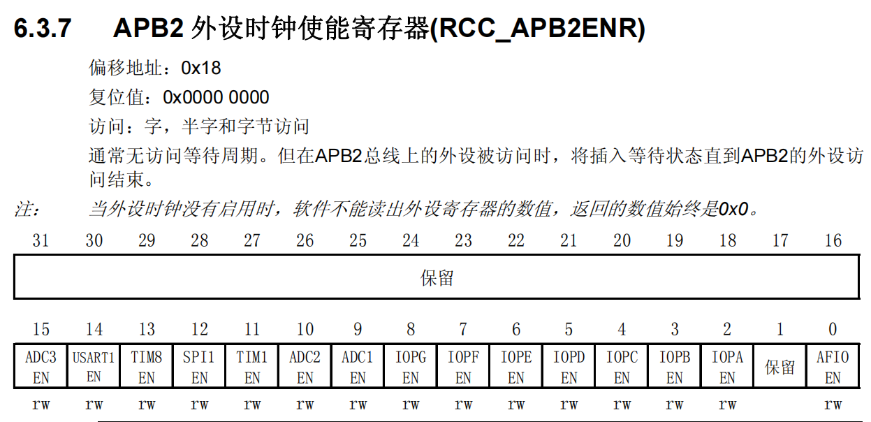
It can be seen that each bit represents an "operation", which may be a bit abstract. For example, if we want to enable GPIOF, we only need to set the zero position 1 of the binary number, with the high order on the left and the low order on the right. At this time, the value should be 000 0001. In order to facilitate the expression, it can be transformed into hexadecimal expression, 0x00000001. The rest of the work is left to the register. Therefore, through the or operation of C language, we can combine the two into one and enable the two GPIO ports at the same time.
GPIO port initialization
After enabling the pin, we also need to configure it. The configuration contents include configuration object, transmission rate and input / output mode.
Before that, we first understand CRL and CRH, that is, port configuration low register and port configuration high register, which are collectively referred to as configuration registers.
CRL represents the lower 8 bits of GPIO port, i.e. pins 0 ~ 7, and CRH represents pins 8 ~ 15.
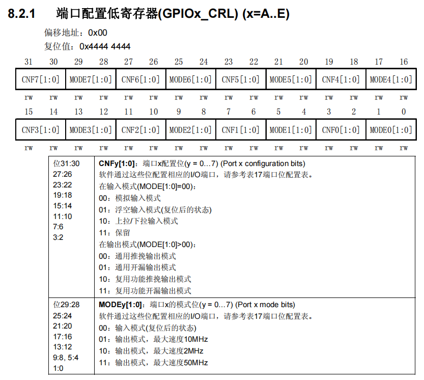
It can be seen from the reference manual that every 4 bits in the 32-bit register control one io port, which exactly corresponds to 8.
Next, we need to configure the register through the function. First, we need to define another structure
GPIO_InitTypeDef GPIO_InitStructure;
The structure has three elements: configuration object, transmission rate and input / output mode from top to bottom.
typedef struct
{
  uint16_t GPIO_Pin;             /*!< Specifies the GPIO pins to be configured.
                                      This parameter can be any value of @ref GPIO_pins_define */

  GPIOSpeed_TypeDef GPIO_Speed;  /*!< Specifies the speed for the selected pins.
                                      This parameter can be a value of @ref GPIOSpeed_TypeDef */

  GPIOMode_TypeDef GPIO_Mode;    /*!< Specifies the operating mode for the selected pins.
                                      This parameter can be a value of @ref GPIOMode_TypeDef */
}GPIO_InitTypeDef;
To enable PB5 and PE5, we select pin 5 for the first parameter, the fastest 50MHz for the second rate parameter, and the push-pull output mode for the third.
GPIO_InitStructure.GPIO_Pin = GPIO_Pin_5;//Pin 5
GPIO_InitStructure.GPIO_Speed = GPIO_Speed_50MHz;//Pin transfer rate 50 MHz
GPIO_InitStructure.GPIO_Mode = GPIO_Mode_Out_PP;//Push pull output mode
STM32 has 4 output modes and 4 input modes. Please refer to relevant materials for the specific working principle of these 8 modes. For LED lighting, push-pull output is the most simple and convenient, so push-pull output is adopted.
Then we initialize the corresponding pin with the initialization function.
GPIO_Init(GPIO_TypeDef* GPIOx, GPIO_InitTypeDef* GPIO_InitStruct);
Turn on the LED
Finally, let's know an ODR -- port output data register. As the name suggests, it is responsible for outputting high and low level signals.
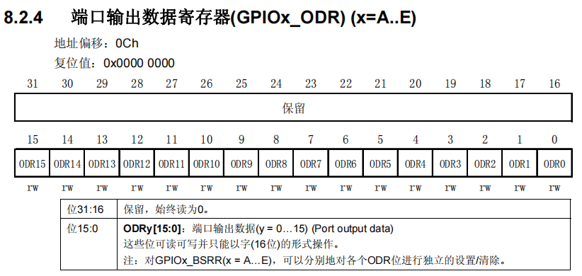
Call the pin control function, generate potential difference at low level, and the LED is on.
GPIO_ResetBits(GPIO_TypeDef* GPIOx, uint16_t GPIO_Pin);
In fact, the essence of this series is to drive the chip to complete the corresponding functions by adjusting each bit signal of the register, and the library function makes it linguistic for us to understand.