preface
ADC is widely used in the project. ADC and DAC are digital / analog converters. But I don't use much DAC, because I usually use sensors to detect external analog quantities, and then convert them into digital quantities for data processing and application, such as temperature and humidity sensors, inductors, black-and-white tracking modules, etc.
ADC (analog to digital converter) is a kind of equipment used to convert analog continuous signals into digital discrete signals. An Analog-to-digital converter can provide a signal for measurement. In contrast, the device becomes a digital to analog converter, that is, DAC. It is a device DAC that converts digital quantity into analog.
Why do you need a digital / analog converter?
Quoting such a passage, in the computer control system, various detection devices must be used to provide relevant parameters (such as speed, pressure, temperature, etc.) of the controlled object at any time with continuously changing voltage or current as analog quantity. The input of the computer must be digital, so an analog-to-digital converter is needed to achieve the purpose of control.
Attached:
(insert a sentence, the full English name of Baidu adc, and the first one pushed by Baidu is Attack Damage Carry)

1, Input channel and mode of ADC
1. Input channel
The ADC function of STM32F103 is fairly good. It has three ADCs, namely ADC1/2/3, of which ADC1/ADC3 supports DMA transmission and ADC2 does not. ADC1 and ADC2 have 16 external channels, and ADC3 has 8 external channels according to different CPU pins.
For the concept of input channel, we can understand it as a GPIO pin configured as input mode for data input. Generally speaking, 16 external channels correspond to 16 GPIO pins. For example, channel 1 corresponds to PA0.
(note) the channel pin of ADC cannot have multiplexing function!!! That will cause the collected data to be extremely inaccurate!
The input channel is divided into regular channel and injection channel.
The regular channel is an ordinary channel, and the injection channel is a "queue jumping" channel, which is a channel with high priority. If the regular channel encounters queue jumping of the injection channel, the data conversion of the injection channel must be completed first, and then the data conversion of the regular channel.
Since there are so many channels, which channel performs data conversion first is determined by the rule sequence register SQR3/2/1 of the rule channel (for the rule channel), and the injection channel is determined by the injection sequence register JSQR. The specific setting method can be read in the Chinese / English manual, but we generally call the library function.
2. Pattern
ADC data collection can be divided into the following types: (the complete code resources are at the end of the article)
1) Independent mode single channel acquisition
Independent mode is to select ADC1 or ADC2 or ADC3, and single channel is to use a GPIO pin.
DMA transmission can be used. You can use DMA for data transmission only by configuring the ADC and DMA structures of the standard library.
/**
  * @brief  Configure ADC and DMA operating modes
  * @param  nothing
  * @retval nothing
  */
void ADC__DMA_Mode_Config(void)
{
	DMA_InitTypeDef DMA_InitStructure;
	ADC_InitTypeDef ADC_InitStructure;
	// Turn on DMA clock
	RCC_AHBPeriphClockCmd(RCC_AHBPeriph_DMA1, ENABLE);
	// Turn on ADC clock
	ADC_APBxClock_FUN ( ADC_CLK, ENABLE );
	// Reset DMA controller
	DMA_DeInit(ADC_DMA_CHANNEL);
	// Configure DMA initialization structure
	// Peripheral base address: ADC data register address
	DMA_InitStructure.DMA_PeripheralBaseAddr = ( uint32_t ) ( & ( ADCx->DR ) );
	// The memory address is actually an internal SRAM variable
	DMA_InitStructure.DMA_MemoryBaseAddr = (uint32_t)&ADC_ConvertedValue;
	// Data source from peripheral
	DMA_InitStructure.DMA_DIR = DMA_DIR_PeripheralSRC;
	// The buffer size is 1, and the size of the buffer should be equal to the size of the memory
	DMA_InitStructure.DMA_BufferSize = 1;
	// There is only one peripheral register, and the address does not need to be incremented
	DMA_InitStructure.DMA_PeripheralInc = DMA_PeripheralInc_Disable;
	// Fixed memory address
	DMA_InitStructure.DMA_MemoryInc = DMA_MemoryInc_Disable;
	// The size of peripheral data is half word, that is, two bytes
	DMA_InitStructure.DMA_PeripheralDataSize = DMA_PeripheralDataSize_HalfWord;
	// The size of memory data is also half word, which is the same as that of peripheral data
	DMA_InitStructure.DMA_MemoryDataSize = DMA_MemoryDataSize_HalfWord;
	// Cyclic transmission mode
	DMA_InitStructure.DMA_Mode = DMA_Mode_Circular;
	// The priority of DMA transmission channel is high. When a DMA channel is used, the priority setting does not affect
	DMA_InitStructure.DMA_Priority = DMA_Priority_High;
	// Memory to memory mode is prohibited because it is from peripheral to memory
	DMA_InitStructure.DMA_M2M = DMA_M2M_Disable;
	// Initialize DMA
	DMA_Init(ADC_DMA_CHANNEL, &DMA_InitStructure);
	// Enable DMA channel
	DMA_Cmd(ADC_DMA_CHANNEL , ENABLE);
	// ADC mode configuration
	// Only one ADC is used, which belongs to single mode
	ADC_InitStructure.ADC_Mode = ADC_Mode_Independent;
	// Scan mode is prohibited, multi-channel is required, and single channel is not required
	ADC_InitStructure.ADC_ScanConvMode = DISABLE ;
	// Continuous conversion mode
	ADC_InitStructure.ADC_ContinuousConvMode = ENABLE;
	// The software can be started without external trigger conversion
	ADC_InitStructure.ADC_ExternalTrigConv = ADC_ExternalTrigConv_None;
	// Align conversion results right
	ADC_InitStructure.ADC_DataAlign = ADC_DataAlign_Right;
	// 1 conversion channel
	ADC_InitStructure.ADC_NbrOfChannel = 1;
	// Initialize ADC
	ADC_Init(ADCx, &ADC_InitStructure);
	// Configure the ADC clock to 8-division of PCLK2, i.e. 9MHz
	RCC_ADCCLKConfig(RCC_PCLK2_Div8);
	// Configure the ADC channel conversion order as 1, the first conversion, and the sampling time as 55.5 clock cycles
	ADC_RegularChannelConfig(ADCx, ADC_CHANNEL, 1, ADC_SampleTime_55Cycles5);
	// Enable ADC DMA request
	ADC_DMACmd(ADCx, ENABLE);
	// Turn on the ADC and start the conversion
	ADC_Cmd(ADCx, ENABLE);
	// Initialize ADC calibration register
	ADC_ResetCalibration(ADCx);
	// Wait for calibration register initialization to complete
	while(ADC_GetResetCalibrationStatus(ADCx));
	// ADC start calibration
	ADC_StartCalibration(ADCx);
	// Wait for calibration to complete
	while(ADC_GetCalibrationStatus(ADCx));
	// Since no external trigger is used, ADC conversion is triggered by software
	ADC_SoftwareStartConvCmd(ADCx, ENABLE);
}
Another way is to call library functions directly
/*
Function: AD sampling
 Inlet parameter: channel of ADC1
 Return value: the AD conversion result is 16 bits
*/
uint16_t Get_ADC(uint8_t ch)
{
//Set the rule group channel, a sequence and sampling time of the specified ADC
	ADC_RegularChannelConfig(ADC1, ch, 1, ADC_SampleTime_1Cycles5 );	//ADC1,ADC channel, sampling time is 1.5 cycles
	ADC_SoftwareStartConvCmd(ADC1, ENABLE);
	//Enable the software conversion startup function of the specified ADC1
	while(!ADC_GetFlagStatus(ADC1, ADC_FLAG_EOC ));
	//Wait for the conversion to end
	return ADC_GetConversionValue(ADC1);
	//Returns the last conversion result of ADC1 rule group
}
The ADC conversion completion interrupt can also be used to read the conversion value of the ADC
void ADC_IRQHandler(void)
{
	if (ADC_GetITStatus(ADCx,ADC_IT_EOC)==SET)
	{
		// Read the conversion value of ADC
		ADC_ConvertedValue = ADC_GetConversionValue(ADCx);
	}
	ADC_ClearITPendingBit(ADCx,ADC_IT_EOC);
}
The last one is the operation register, which is a chip of WCHF103 used in smart car. It has only one ADC, but I used three inductors. It has only one ADC and does not use DMA. The program mentioned "time-sharing multiplexing", that is, this method is used. Three inductors need to collect three groups of data. You can only wait for the data collection of the last inductor to collect the data of the inductor. The programming function does ensure that it directly operates the data register. After the conversion of the last data, you can collect the next data. Program execution is sequential, which also ensures this.
This is a bit of time to make up for the lack of chip resources.
For "time-sharing multiplexing", Baidu Encyclopedia explains that it uses different periods of the same physical connection to transmit different signals, which can achieve the purpose of multiplexing. In the network, it is used to transmit multiple data on one line.
//-------------------------------------------------------------------------------------------------------------------
//  @Brief ADC conversion once
//  @Param ch select ADC channel
//  @Param resolution (8 bits, 10 bits, 12 bits)
//  @return     void
//  Sample usage:               adc_convert(ADC_IN0_A0, ADC_8BIT);  // The acquisition A0 port returns the AD value with 8-bit resolution
//-------------------------------------------------------------------------------------------------------------------
uint16 adc_convert(ADCCH_enum ch, ADCRES_enum resolution)
{
    //Set the rule group channel, a sequence and sampling time of the specified ADC
    ADC_RegularChannelConfig(ADC1, (uint8)ch, 1, ADC_SampleTime_1Cycles5);  //ADC1,ADC channel, sampling time is 1.5 cycles
    ADC1->CTLR2 |= ((uint32_t)0x00500000);                                  //Enable the software conversion startup function of the specified ADC1
    while((ADC1->STATR & ADC_FLAG_EOC) == (uint8_t)RESET);                  //Wait for the conversion to end
    return ((ADC1->RDATAR)>>resolution);                                    //Returns the last conversion result of ADC1 rule group
}
2) Independent mode multi-channel acquisition
Independent mode multi-channel acquisition refers to using multiple channels of one ADC to collect data. Multi channel ADC acquisition generally adopts DMA to transfer the conversion value of ADC to the specified storage area through DMA.
3) Dual ADC mode acquisition
For ADC acquisition in independent mode, the acquisition of the next channel will not be carried out until one channel is acquired and the conversion is completed. The mechanism of dual ADC is to use two ADCs to sample one or more channels at the same time. One of the biggest advantages of dual ADC mode over independent mode is to improve the sampling rate and make up for the disadvantage that a single ADC is not fast enough.
There are several modes:
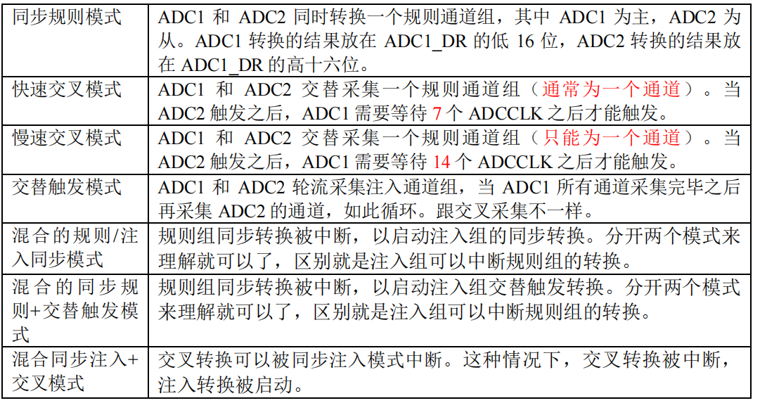
Taking the synchronization rule mode as an example, the synchronization rule mode is that ADC1 and ADC2 convert a regular channel group at the same time, ADC1 is the master, ADC2 is the slave, and the conversion result of ADC1 is placed in ADC1_ The lower 16 bits of DR and the result of ADC2 conversion are placed in ADC1_ The upper 16 digits of Dr. And the DMA function must be turned on.
2, Trigger mode of ADC
List the following three ways:
1. Through ADC control register
ADC conversion can be controlled by ADC control register 2: ADC_ It is controlled by the ADON bit of CR2. The conversion starts when writing 1 and stops when writing 0. This is the simplest and best understood control method to turn on ADC conversion.
2. External IO port
3. Internal timer
Generally, there is no external trigger conversion, and the software can be opened.
3, Resource connection
I will continue to optimize the deficiencies.
Comment, comment, email, send information.