Preface
Tip: Learning content comes from the following literature
catlikecoding.com
Tip: The following is the main body of this article. The following cases can be used as reference.
1.0,Shaders
In order to draw something, the CPU must tell the GPU what to draw and how to draw it. Typically, a grid is drawn. How to draw is defined by Shader, which is the GPU of a set of instructions. In addition to the grid, shader needs additional information to complete its work, including the object's transformation matrix and material properties.
Unity's LW/Universal and HD RPs allow you to design shaders using the Shader Graph package, which generates shader code for you. But our custom RP doesn't support it, so we have to write our own shader code. This gives us full control and understanding of the role of the shader.
1.1,Unlit Shader
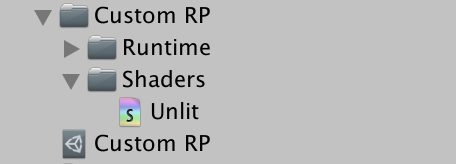
Our first shader will simply draw a solid grid without any lighting. A shader asset can be created through an option in the Assets / Create / Shader menu. UnlitShader is the most appropriate, but we will remove all default code from the created shader file. Name the asset Unlit and place it in the new shader folder under the custom RP.
In most cases, the shader code looks like c#code, but it contains a variety of different methods, including some old parts that used to make sense but are no longer.
Shader is defined as a class, but only the shader keyword is followed by a string to create an entry for it in the shader drop-down menu of materials. We use custom RP/Unlit. It is followed by a code block that contains more blocks preceding the keywords. There is an attribute block to define material properties, then a SubShader block, which requires a Pass block inside, which defines a way to render things. Create the structure with empty blocks:
Shader "Custom RP/Unlit" {

	Properties {}

	SubShader {

		Pass {}
	}
}
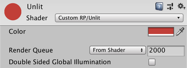
This defines a minimal shader that compiles and allows us to create a material that uses it:
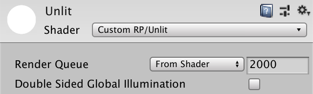
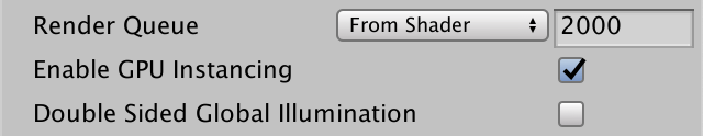
The default shader implements a pure white rendering grid. Material displays the default properties of the rendering queue, which is automatically obtained from the shader and set to 2000, which is the default value for opaque geometries. It also has a switch to enable double-sided global lighting, but this has nothing to do with us.
1.2,HLSL Programs
The language we use to write shader code is the advanced shading language, referred to as HLSL for short. We have to put it in the Pass block, between the HLSLPROGRAM and ENDHLSL keywords. We have to do this because it can also put other non-hlsl code in the Pass block:
		Pass {
			HLSLPROGRAM
			ENDHLSL
		}
In order to draw a grid, the GPU must rasterize all triangles and convert them to pixel data. It does this by converting vertex coordinates from 3D space to 2D visualization space and filling in all the pixels covered by the resulting triangle. These two steps are controlled by a separate shading program, which we must define. The first is called the vertex kernel/program/shader, and the second is called the fragment kernel/program/shader. A fragment corresponds to a display pixel or texture texture, although it may not represent the end result because it may be overwritten when something is drawn on it later.
We have to identify two programs by one name, which is done with the pragma directive. These are single-line statements starting with #pragma, followed by vertices or fragments and their associated names. We will use UnlitPassVertex and UnlitPassFragment:
			HLSLPROGRAM
			#pragma vertex UnlitPassVertex
			#pragma fragment UnlitPassFragment
			ENDHLSL
What does pragma mean?
The word pragma comes from Greek and refers to an action or something to do. It is used in many programming languages to issue special compiler instructions
The shader compiler will now complain that it cannot find the declared shader kernel. We must write LSL functions with the same name to define their implementation. We can do this directly under the pragma directive, but we will put all the HLSL code in a single file. Specifically, we'll use UnlitPass. The HLSL files are in the same asset folder. We can instruct the shader compiler to insert the contents of the file by adding a #include directive with a relative path to the file:
			HLSLPROGRAM
			#pragma vertex UnlitPassVertex
			#pragma fragment UnlitPassFragment
			#include "UnlitPass.hlsl"
			ENDHLSL
Unity does not have a convenient menu option to create HLSL files, so you must copy the shader file, rename it UnlitPass, change its file extension from external to HLSL, and clear its contents:

1.3, Include Guard (Reference Defense)
HLSL files are used to group code, just like c#classes, although HLSL has no class concept. There is only one global scope except the local scope of the code block. So anything can be accessed anywhere. Include files are also different from using namespaces. It inserts the entire contents of the file into the location of the include directive, so if you include the same file multiple times, you will get duplicate code, which is likely to result in compiler errors. To prevent this, we will be in UnlitPass. Add an include guard to HLSL
You can use the #define directive to define any identifier, usually in uppercase. We'll use it to define CUSTOM_at the top of the file UNLIT_ PASS_ INCLUDED:
#define CUSTOM_UNLIT_PASS_INCLUDED
This is an example of a simple macro that defines an identifier. If it exists, that means our files are already included. So we don't want to include it anymore. If you use different wording, we only want to insert code when it has not been defined. We can check with the #ifndef directive. Do this before defining the macro:
#ifndef CUSTOM_UNLIT_PASS_INCLUDED
#define CUSTOM_UNLIT_PASS_INCLUDED
All code following #ifndef will be skipped, so if the macro is already defined, it will not be compiled. We must end its scope by adding the #endif directive at the end of the file:
#ifndef CUSTOM_UNLIT_PASS_INCLUDED
#define CUSTOM_UNLIT_PASS_INCLUDED
#endif
Now we can make sure that all the code associated with the file is not inserted multiple times, even if we include it more than once.
1.4, Shader Functions(Shader function)
We define the shader function within the scope of the include guard. They are written like the c# method without any access modifiers. Start with a simple void function that does nothing:
#ifndef CUSTOM_UNLIT_PASS_INCLUDED
#define CUSTOM_UNLIT_PASS_INCLUDED

void UnlitPassVertex () {}

void UnlitPassFragment () {}

#endif
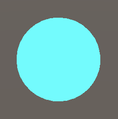
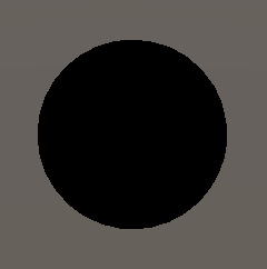
This is enough for our shader to compile. The result may be a default cyan shader, if any is displayed:
In order to produce a valid output, we must have the fragment function return a color. Color is defined as a floating point 4 vector containing red, green, blue, and alpha elements. You can define pure black by float4(0.0, 0.0, 0.0, 0.0), but you can also write a zero because a single value automatically expands to a full vector. The alpha value doesn't matter because we created an opaque shader, so 0 is good:
float4 UnlitPassFragment () {
	return 0.0;
}
Why use 0.0 instead of 0?
0.0 is a floating point number and 0 is an integer. Although the values are the same, they are not the same for the compiler.
Use float or half precision?
Most mobile GPU s support two types of accuracy, with half being more efficient. Therefore, if you need to optimize for mobile devices, you should use half as much as possible. Empirically, float s are used for location and texture coordinates and half for everything else, as long as the results are good enough. fixed can usually be equivalent to half
At this point, the shader compiler will fail because our functions lack semantics. We have to express what we mean by the returned values because we may produce a lot of data with different meanings. In this example, we provide a default system value for the rendering target by writing a colon and SV_after the parameter list of UnlitPassFragment TARGET to indicate:
float4 UnlitPassFragment () : SV_TARGET {
	return 0.0;
}
1.5, Space Transformation
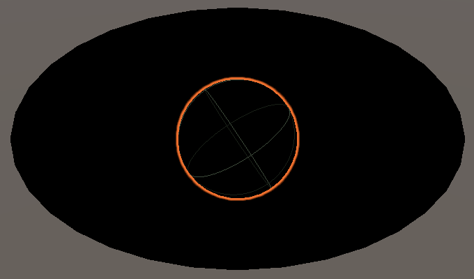
When all vertices are set to zero, the grid collapses to a point, and nothing is rendered. The main work of the vertex function is to convert the original vertex position into the correct space. When a function is called, it is provided if we request available vertex data. We do this by adding a parameter to UnlitPassVertex. We need the vertex location, which is defined in object space, so we named it positionOS, using the same Convention as Unity's new rp. The location type is float3 because it is a 3D point. Let's go back to it first and add 1 as the fourth required component through float4 (positionOS, 1.0):
float4 UnlitPassVertex (float3 positionOS) : SV_POSITION {
	return float4(positionOS, 1.0);
}
Is the Position of the vertex not float4?
Generally, points in 3D space are defined using a 4D vector, with the fourth component set to 1, and the directional vector set to zero. This allows the correct transformation of position and direction using the same transformation matrix. However, this technique is required only when the position and direction are mixed, which is not usually the case. Instead, it can use different codes to simplify the calculation of rotation conversions
We must also add semantics to the input because vertex data can contain more than one location. In this case, we need to add a color POSITION directly after the parameter name:
float4 UnlitPassVertex (float3 positionOS : POSITION) : SV_POSITION {
	return float4(positionOS, 1.0);
}
The grid is displayed again, but it is incorrect because our output is in the wrong space. Spatial conversion requires a matrix, which is sent to the GPU when the graph is drawn. We have to add these matrices to our shaders, but because they are always the same, we will put the standard input provided by Unity in a separate HLSL file, which can either keep the structure of the code or include it in other shaders. Add a UnityInput. The HLSL file is placed in the ShaderLibrary folder under the custom RP to mirror the folder structure of Unity's RP.

With CUSTOM_UNITY_INPUT_INCLUDED references the protection start file and then defines a global scope named unity_ Floating-point 4x4 matrix of ObjectToWorld. In the c#class, this defines a field, but here it is called a uniform value. It is set by the GPU once per drawing and remains constant throughout the drawing process for calls to all vertex and fragment functions:
#ifndef CUSTOM_UNITY_INPUT_INCLUDED
#define CUSTOM_UNITY_INPUT_INCLUDED

float4x4 unity_ObjectToWorld;

#endif
We can use a matrix to convert object space into world space. Because this is a common feature, let's create a function for it and put it in another file, this time common. hlsl is in the same ShaderLibrary folder. We include UnityInput here and declare a TransformObjectToWorld function with float3 for both input and output:
#ifndef CUSTOM_COMMON_INCLUDED
#define CUSTOM_COMMON_INCLUDED

#include "UnityInput.hlsl"

float3 TransformObjectToWorld (float3 positionOS) {
	return 0.0;
}

#endif
Spatial conversion is done by calling the mul function with matrices and vectors. In this case, we do need a 4D vector, but since its fourth component is always 1, we can add it ourselves using float4(positionOS, 1.0). The result is still a 4D vector, always 1 as its fourth component. We can extract the first three components from a vector by accessing its xyz attribute, which is called the swizzool operation:
float3 TransformObjectToWorld (float3 positionOS) {
	return mul(unity_ObjectToWorld, float4(positionOS, 1.0)).xyz;
}
We can now switch to world space in UnlitPassVertex. The first includes Common. HLSL is directly above the function. Because it exists in different folders, we can use relative paths.../ShaderLibrary/Common.hlsl found it. Then use TransformObjectToWorld to calculate a positionWS variable and return it instead of the location of the object space:
#include "../ShaderLibrary/Common.hlsl"

float4 UnlitPassVertex (float3 positionOS : POSITION) : SV_POSITION {
	float3 positionWS = TransformObjectToWorld(positionOS.xyz);
	return float4(positionWS, 1.0);
}
The result is still wrong because we need to find a place in even clipping space. This space defines a cube that contains everything in the camera view, distorted into trapezoids when the camera is perspective. The conversion from world space to this space can be accomplished by multiplying it with the view projection matrix, which explains the camera's position, direction, projection, field of view, and near-far shear plane. It is available unity_ObjectToWorld matrix, so add it to UnityInput.hlsl:
float4x4 unity_ObjectToWorld;

float4x4 unity_MatrixVP;
Add a TransformWorldToHClip to the public. hlsl, which works the same way as TransformObjectToWorld, except that its input is in world space, it uses another matrix, and produces a floating point number of 4:
float3 TransformObjectToWorld (float3 positionOS) {
	return mul(unity_ObjectToWorld, float4(positionOS, 1.0)).xyz;
}

float4 TransformWorldToHClip (float3 positionWS) {
	return mul(unity_MatrixVP, float4(positionWS, 1.0));
}
Let UnlitPassVertex use the function to return the location in the correct space:
float4 UnlitPassVertex (float3 positionOS : POSITION) : SV_POSITION {
	float3 positionWS = TransformObjectToWorld(positionOS.xyz);
	return TransformWorldToHClip(positionWS);
}
1.6, Core Library
The two functions we just defined are very common and are also included in the Core RP Pipeline package. Core libraries define a lot more useful and important things, so let's install this package, remove our own definitions, and include the relevant files, in this case Packages/com. Unity. Render-pipeles. Core/ShaderLibrary/SpaceTransforms. Hlsl:
//float3 TransformObjectToWorld (float3 positionOS) {
//	return mul(unity_ObjectToWorld, float4(positionOS, 1.0)).xyz;
//}

//float4 TransformWorldToHClip (float3 positionWS) {
//	return mul(unity_MatrixVP, float4(positionWS, 1.0));
//}

#include "Packages/com.unity.render-pipelines.core/ShaderLibrary/SpaceTransforms.hlsl"
This cannot be compiled because of the code in SpaceTransforms. hlsl does not assume unity_ObjectToWorld exists. Instead, it expects the related matrix to be defined by the macro as UNITY_MATRIX_M, so let's write #define UNITY_on a separate line before including the file MATRIX_ M unity_ObjectToWorld to complete. After that, all UNITY_that happens MATRIX_ M will be replaced with unity_ObjectToWorld. We will find out later why:
#define UNITY_MATRIX_M unity_ObjectToWorld

#include "Packages/com.unity.render-pipelines.core/ShaderLibrary/SpaceTransforms.hlsl"
For inverse matrix unity_ The same is true for worldtobject, which should go through UNITY_MATRIX_I_M to define, UNITY_MATRIX_V to define unity_MatrixVP, UNITY_MATRIX_VP to define. Finally, through UNITY_MATRIX_P-defined projection matrix, which can be used as glstate_matrix_projection. We don't need these extra matrices, but if we don't include them, the code won't compile:
#define UNITY_MATRIX_M unity_ObjectToWorld
#define UNITY_MATRIX_I_M unity_WorldToObject
#define UNITY_MATRIX_V unity_MatrixV
#define UNITY_MATRIX_VP unity_MatrixVP
#define UNITY_MATRIX_P glstate_matrix_projection
Add additional matrices to UnityInput:
float4x4 unity_ObjectToWorld;
float4x4 unity_WorldToObject;

float4x4 unity_MatrixVP;
float4x4 unity_MatrixV;
float4x4 glstate_matrix_projection;
The last thing missing is not a matrix. It is unity_WorldTransformParams, which contains some transformation information that we don't need here. It is a vector defined as real4, real4 itself is not a valid type, but an alias for float4 or half4, depending on the target platform:
float4x4 unity_ObjectToWorld;
float4x4 unity_WorldToObject;
real4 unity_WorldTransformParams;
This alias and many other basic macros are defined for each graphics API by including Packages / com.unity.render-pipelines.core / ShaderLibrary / Common.hlsl to get all the information. In Contains UnityInput. Before hlsl, please visit our Common. Do this in the HLSL file. If you are curious about their contents, you can also view these files:
#include "Packages/com.unity.render-pipelines.core/ShaderLibrary/Common.hlsl"
#include "UnityInput.hlsl"
1.7,Color
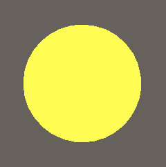
The color of the rendered object can be changed by adjusting the UnlitPassFragment. For example, we can set float4(1.0, 1.0, 0.0, 1.0) to yellow instead of 0:
float4 UnlitPassFragment () : SV_TARGET {
	return float4(1.0, 1.0, 0.0, 1.0);
}
In order to make it possible to configure the color of each material, we must define it as a uniform value. Under the include directive, execute before the UnlitPassVertex function. We need a float4 and name it _ BaseColor. The underline before is the standard way to represent material properties. Return this value in UnlitPassFragment instead of the hard-coded color:
#include "../ShaderLibrary/Common.hlsl"

float4 _BaseColor;

float4 UnlitPassVertex (float3 positionOS : POSITION) : SV_POSITION {
	float3 positionWS = TransformObjectToWorld(positionOS);
	return TransformWorldToHClip(positionWS);
}

float4 UnlitPassFragment () : SV_TARGET {
	return _BaseColor;
}
Let's go back to black, because the default value is 0. In order to link it to materials, we must add _in the attribute block of the Unlit shader file BaseColor:
	Properties {
		_BaseColor
	}
The property name must be followed by a string for the inspector and a Color type identifier, just like providing parameters to a method:
_BaseColor("Color", Color)
Finally, we must provide a default value, in this case by assigning it a list of four numbers. We use white:
_BaseColor("Color", Color) = (1.0, 1.0, 1.0, 1.0)
Now you can create multiple materials with our shader, each with a different color.
2.0, Batching (batch)
Each drawing call requires communication between the CPU and the GPU. If there is a large amount of data to send to the GPU, it may waste time waiting. When the CPU is busy sending data, it cannot do anything else. Both of these issues reduce the frame rate. Now our approach is simple: each object has its own drawing call. This is the worst way, although we end up sending very little data, so it's OK now.
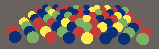
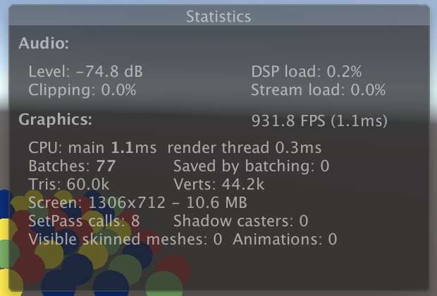
For example, I made a scene with 76 spheres, each using four materials: red, green, yellow, and blue. Rendering requires 78 draw calls, 76 spheres, 1 sky box, and 1 clear render target.
If you open the Stats panel of the game window, you can see an overview of what the rendering frame needs. The interesting fact here is that it shows 77 batches - ignoring clear - of which 0 are saved by the batch:
2.1, SRP Batcher(SRP Batcher)
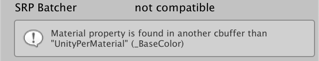
Batch processing is a process that combines drawing calls to reduce communication time between CPU s and GPU s. The easiest way is to enable SRP batch programs. However, this only applies to compatible shaders, which our Unlit shader is not. You can verify this by selecting it in the inspector. A SRP batch line indicates incompatibility, and a reason is given below it:
SRP batches do not reduce the number of decimation calls, but make them more streamlined. It caches material properties on the GPU so that they don't have to be sent every time a drawing call is made. This reduces both the amount of data that needs to be communicated and the work that the CPU must do each drawing call. This is only valid if the shader follows a strict structure of uniform data.
All material properties must be defined in a specific memory buffer, not globally. This is done by packaging _ BaseColor declares both the cbuffer block and the UnityPerMaterial name. This is similar to a struct declaration, but must end with a semicolon. It does this by adding _ BaseColor isolates it by putting in a specific constant memory buffer, although it is still accessible at the global level:
cbuffer UnityPerMaterial {
	float _BaseColor;
};
Constant buffers are not supported on all platforms -- such as OpenGL ES 2.0 -- so we can use CBUFFER_START and CBUFFER_END macros, instead of using cbuffer directly, are included from the Core RP library. The first takes the buffer name as an argument, just like it is a function. In this example, we end up with exactly the same results as before, except that the cbuffer code will not exist on platforms that do not support it:
CBUFFER_START(UnityPerMaterial)
	float4 _BaseColor;
CBUFFER_END
We also need to deal with unity_ObjectToWorld, unity_WorldToObject and unity_WorldTransformParams do this and must be grouped in the UnityPerDraw buffer:
CBUFFER_START(UnityPerDraw)
	float4x4 unity_ObjectToWorld;
	float4x4 unity_WorldToObject;
	real4 unity_WorldTransformParams;
CBUFFER_END
In this example, if we use a specific set of values, we need to define them all. For conversion groups, we need to include float4 unity_even if we don't use it LODFade. Order doesn't matter, but Unity places it directly in unity_ After WorldToObject, so we'll do the same:
CBUFFER_START(UnityPerDraw)
	float4x4 unity_ObjectToWorld;
	float4x4 unity_WorldToObject;
	float4 unity_LODFade;
	real4 unity_WorldTransformParams;
CBUFFER_END

Compatible with our shader, the next step is to enable the SRP batch program, which is done by setting up GraphicsSettings. useScriptableRenderPipelineBatching is true. We only need to do this once, so let's do this when the pipeline instance is created by adding a constructor method to CustomRenderPipeline:
	public CustomRenderPipeline () {
		GraphicsSettings.useScriptableRenderPipelineBatching = true;
	}
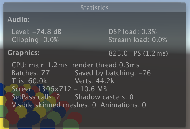
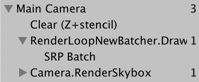
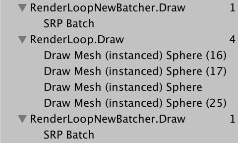
The Statistics panel shows that 76 batches have been saved, but they are negative. The frame debugger is now also in RenderLoopNewBatcher. A SRP Batch entry appears under Draw, but remember that it's not a single draw call, it's their optimized queue
2.2, Many Colors (multiple colors)
Even if we use four materials, we can get a batch. This is possible because all their data is cached on the GPU, and each drawing call only needs to contain an offset to the correct memory location. The only limitation is that the memory layout of each material needs to be the same, because we use the same shaders for all materials, and each shader contains only one color attribute. Unity does not compare the exact memory layout of the material; it just batches drawing calls that use exactly the same shader variants.
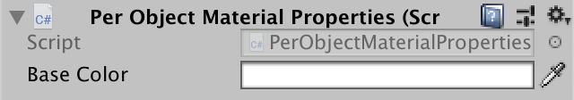
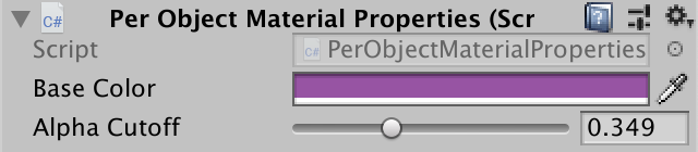
It works well if only a few different colors are needed, but if you want to give each sphere its own color, you need to create more materials. So would it be more convenient if you could set the color for each dynamic object? This is not possible by default, but it can be supported by creating custom component types. Name it PerObjectMaterialProperties. As an example, place it in the Examples folder under Custom RP.
The idea is that a game object can be attached to a PerObjectMaterialProperties component that has a "Base Color" configuration option that will be used to set _for it BaseColor material properties. It needs to know the identifier of the shader attribute, which can be passed through Shader.PropertyToID retrieves the identifier and stores it in a static variable, as it does for the shader pass identifier in CameraRenderer, but in this case it is an integer.
using UnityEngine;

[DisallowMultipleComponent]
public class PerObjectMaterialProperties : MonoBehaviour {

	static int baseColorId = Shader.PropertyToID("_BaseColor");

	[SerializeField]
	Color baseColor = Color.white;
}
Setting the material properties of each object is done through the MaterialPropertyBlock object. We only need one instance of PerObjectMaterialProperties and it can be reused, so declare a static field for it:
static MaterialPropertyBlock block;
If you don't already have a block, create a new one, call SetColor on it using the attribute identifier and color, and then apply the block to the Renderer component of the game object through SetPropertyBlock, which copies its settings. Do this in OnValidate so that the results immediately appear in the editor:
	void OnValidate () {
		if (block == null) {
			block = new MaterialPropertyBlock();
		}
		block.SetColor(baseColorId, baseColor);
		GetComponent<Renderer>().SetPropertyBlock(block);
	}
When is OnValidate called?
Once the component is loaded or changed, OnValidate is called in the Unity editor. Therefore, each time the scene is loaded and the component is edited. As a result, each color immediately appears and responds to editing.
Add components to 24 balls and give them different colors
I add this component to 24 arbitrary spheres and give them different colors:
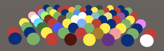
(Using MaterialPropertyBlock interrupts the SRP batch) Unfortunately, the SRP batch process cannot process the material properties of each object. Therefore, these 24 spheres fall back to a regular drawing call, and other spheres may also be divided into batches due to sorting
In addition, OnValidate will not be called in a build. To make individual colors appear there, we must also apply them in Awake by calling OnValidate there:
	void Awake () {
		OnValidate();
	}
2.3, GPU Instancing(GPU instantiation)
There is also a way to combine DrawCall s, which works well with object-by-object material properties. This is called GPU instantiation, which works by making a drawing call to multiple objects with the same grid object at once. The CPU collects the transformations and material properties of each object, puts them into an array, and sends them to the GPU. The GPU then iterates through all entries and renders them in the order provided.
Because GPU instances need to provide data through arrays, our shaders do not currently support that data. The first step in doing this is to add #pragma multi_above the vertices and fragment compilation fragments of the shader's Pass block Compile_ Instancing directive:
			#pragma multi_compile_instancing
			#pragma vertex UnlitPassVertex
			#pragma fragment UnlitPassFragment
This will cause Unity to generate two variants of the shader, one that supports GPU instantiation and one that does not support GPU instantiation. There is also a switch option in the material checker that allows us to choose which version to use for each material:
Support for GPU instantiation requires method changes, including UnityInstancing from the core shader library. HLSL file. Defining UNITY_MATRIX_M and other macros followed by and containing SpaceTransforms. This was done before hlsl:
#define UNITY_MATRIX_P glstate_matrix_projection

#include "Packages/com.unity.render-pipelines.core/ShaderLibrary/UnityInstancing.hlsl"
#include "Packages/com.unity.render-pipelines.core/ShaderLibrary/SpaceTransforms.hlsl"
UnityInstancing. The purpose of HLSL is to redefine these macros to access the instance data array. However, to do this, you need to know the index of the object being rendered. Indexes are provided through vertex data and need to be made available. UnityInstancing.hlsl defines a macro to simplify this process, but it assumes that the vertex function has a struct parameter.
You can declare a structure (just like a cbuffer) and use it as an input parameter to a function. We can also define semantics within the structure. The advantage of this approach is that it is clearer and easier to read than a long parameter list. Therefore, the positionOS parameter of UnlitPassVertex is wrapped in the Attributes structure to represent vertex input data:
struct Attributes {
	float3 positionOS : POSITION;
};

float4 UnlitPassVertex (Attributes input) : SV_POSITION {
	float3 positionWS = TransformObjectToWorld(input.positionOS);
	return TransformWorldToHClip(positionWS);
}
Object indexes can also be used as vertex attributes when GPU instantiation is used. We can add it at the right time by simply adding UNITY_VERTEX_INPUT_INSTANCE_ID placed in Attributes:
struct Attributes {
	float3 positionOS : POSITION;
	UNITY_VERTEX_INPUT_INSTANCE_ID
};
Next, add UNITY_at the beginning of UnlitPassVertex SETUP_ INSTANCE_ ID (input). This extracts the index from the input and stores it in a global static variable on which other instance macros depend:
float4 UnlitPassVertex (Attributes input) : SV_POSITION {
	UNITY_SETUP_INSTANCE_ID(input);
	float3 positionWS = TransformObjectToWorld(input.positionOS);
	return TransformWorldToHClip(positionWS);
}
That's enough for GPU instantiation to work, because SRP batches take precedence, so we don't have the results we want yet. Instance-by-instance material data is not yet supported. If you want to add it, you need to replace _with an array reference if needed BaseColor. By using UNITY_INSTANCING_BUFFER_START Replaces CBUFFER_START and using UNITY_INSTANCING_BUFFER_END Replaces CBUFFER_END to complete, it requires a parameter. It doesn't have to be the same as when you started, but there's no other reason to set it differently
//CBUFFER_START(UnityPerMaterial)
//	float4 _BaseColor;
//CBUFFER_END

UNITY_INSTANCING_BUFFER_START(UnityPerMaterial)
	float4 _BaseColor;
UNITY_INSTANCING_BUFFER_END(UnityPerMaterial)
Then, the _ Replace BaseColor's definition with UNITY_DEFINE_INSTANCED_PROP(Float 4, _BaseColor):
UNITY_INSTANCING_BUFFER_START(UnityPerMaterial)
	//	float4 _BaseColor;
	UNITY_DEFINE_INSTANCED_PROP(float4, _BaseColor)
UNITY_INSTANCING_BUFFER_END(UnityPerMaterial)
When using instantiation, we now also need to provide an instance index in UnlitPassFragment. For simplicity, we'll use a structure called UNITY_TRANSFER_INSTANCE_ID (input, output) makes the UnlitPassVertex output location and index. Copy the index if it exists. We name this structure Varying like Unity because it contains data that may differ between fragments of the same triangle:
struct Varyings {
	float4 positionCS : SV_POSITION;
	UNITY_VERTEX_INPUT_INSTANCE_ID
};

Varyings UnlitPassVertex (Attributes input) { //: SV_POSITION {
	Varyings output;
	UNITY_SETUP_INSTANCE_ID(input);
	UNITY_TRANSFER_INSTANCE_ID(input, output);
	float3 positionWS = TransformObjectToWorld(input.positionOS);
	output.positionCS = TransformWorldToHClip(positionWS);
	return output;
}
Add this structure as a parameter to UnlitPassFragment. Then use UNITY_as before SETUP_ INSTANCE_ ID to make the index available. Now you need to go through UNITY_ACCESS_INSTANCED_PROP (UnityPerMaterial, _BaseColor) accesses the material property:
float4 UnlitPassFragment (Varyings input) : SV_TARGET {
	UNITY_SETUP_INSTANCE_ID(input);
	return UNITY_ACCESS_INSTANCED_PROP(UnityPerMaterial, _BaseColor);
}
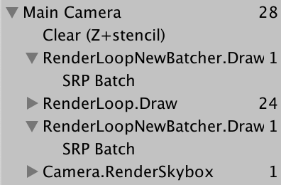
Unity can now combine 24 spheres with the color of each object, reducing the number of drawing calls. Four instantiated drawing calls were made because these spheres still use four of these materials. GPU instantiation applies only to objects that share the same material. When they need to override material colors, they can all use the same material and then allow them to be drawn in batches:
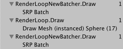
Note that the batch size is limited depending on how much data the target platform and each instance must provide. If you exceed this limit, you will get more than one batch of products. In addition, classification can still divide batches if multiple materials are used.
2.4, Drawing Many Instanced Meshes (drawing multiple instance grids)
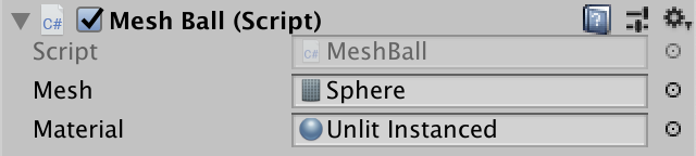
GPU instancing becomes an important advantage when hundreds of objects can be merged in one DC. But it is impractical to manually edit so many objects in the scene. So let's randomly generate them. Create a sample component of MeshBall that generates many objects when it Awake. Cache it_ BaseColor shader properties and add some configuration items needed to support instancing for materials and Mesh:
using UnityEngine;

public class MeshBall : MonoBehaviour {

	static int baseColorId = Shader.PropertyToID("_BaseColor");

	[SerializeField]
	Mesh mesh = default;

	[SerializeField]
	Material material = default;
}
Create a game object with this component. I give it a default sphere grid to draw:
We can generate a lot of new game objects, but that's not necessary. Correspondingly, just fill in the array of transformation matrices and colors and tell the GPU to render the grid with them. This is the most useful place for GPU instancing. You can provide up to 1023 instances at a time, so let's add fields with that length of array and MaterialPropertyBlock s that need to pass color data. In this case, the element type of the color array must be Vector4:
	Matrix4x4[] matrices = new Matrix4x4[1023];
	Vector4[] baseColors = new Vector4[1023];

	MaterialPropertyBlock block;
Create an Awake method that fills the array with random positions within a sphere with a radius of 10 and random RGB color data:
	void Awake () {
		for (int i = 0; i < matrices.Length; i++) {
			matrices[i] = Matrix4x4.TRS(
				Random.insideUnitSphere * 10f, Quaternion.identity, Vector3.one
			);
			baseColors[i] =
				new Vector4(Random.value, Random.value, Random.value, 1f);
		}
	}
In Update, if no block exists, create one and call SetVectorArray on it to configure the color. Graphics is then called with Mesh, sub-mesh index zero, material, matrix array, number of elements, and attribute blocks as parameters. DrawMeshInstanced. Here we set up the block so that mesh ball s can support hot overloading:
	void Update () {
		if (block == null) {
			block = new MaterialPropertyBlock();
			block.SetVectorArray(baseColorId, baseColors);
		}
		Graphics.DrawMeshInstanced(mesh, 0, material, matrices, 1023, block);
	}
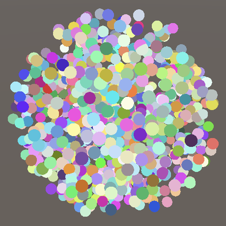
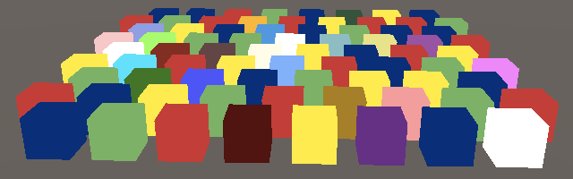
Entering the game mode will result in a dense sphere. How many drawing calls it requires depends on the platform, because the maximum buffer size for each drawing call is different. In my example, rendering requires three drawing calls.
Note that each grid is drawn in the same order as the data we provide. In addition, there are no sorting or culling methods, so once a batch disappears within the view cone, the entire batch disappears.
2.5, Dynamic Batching (Dynamic Batching)
The third way to reduce DC is called dynamic batching. This is an old technique that combines small grids that share the same material into a larger grid that is drawn. However, if the per-object material properties are used, it will fail.
Larger grids are generally generated on demand, so dynamic batching is only available for smaller grids. The sphere is still too big, but the cube can be used. To track the process of viewing it, you need to disable GPU instantiation and then CameraRenderer. Set enableDynamicBatching to true in DrawVisibleGeometry.
		var drawingSettings = new DrawingSettings(
			unlitShaderTagId, sortingSettings
		) {
			enableDynamicBatching = true,
			enableInstancing = false
		};
Also disable the SRP batch processor because it has priority
GraphicsSettings.useScriptableRenderPipelineBatching = false;
Generally speaking, GPU instantiation is better than dynamic batching. There are also some considerations for this method, for example, when different scales are involved, the normal vector of a larger grid cannot be guaranteed to be a unit length. In addition, the drawing order will change because it is now a single grid instead of multiple.
There are also static batches, which work similarly but are marked as static batch objects ahead of time. It has no precautions other than requiring more memory and storage space. RP doesn't care about this, so don't worry too much about it.
2.6, Configuring Batching (Configuring Batching)
That way of doing better may depend on many factors, so it's better to treat them as configurable options. First, add Boolean parameters to control whether dynamic batch processing and GUI instantiation are used for DrawVisibleGeometry instead of hard-coding it:
	void DrawVisibleGeometry (bool useDynamicBatching, bool useGPUInstancing) {
		var sortingSettings = new SortingSettings(camera) {
			criteria = SortingCriteria.CommonOpaque
		};
		var drawingSettings = new DrawingSettings(
			unlitShaderTagId, sortingSettings
		) {
			enableDynamicBatching = useDynamicBatching,
			enableInstancing = useGPUInstancing
		};
		...
	}
Rendering must now provide this configuration and then rely on RP to provide it:
	public void Render (
		ScriptableRenderContext context, Camera camera,
		bool useDynamicBatching, bool useGPUInstancing
	) {
		...
		DrawVisibleGeometry(useDynamicBatching, useGPUInstancing);
		...
	}
CustomRenderPipeline is set in its constructor method with the field tracking option and passed in Render. Also add the bool parameter of the SRP batch program to the constructor instead of always enabling it:
	bool useDynamicBatching, useGPUInstancing;

	public CustomRenderPipeline (
		bool useDynamicBatching, bool useGPUInstancing, bool useSRPBatcher
	) {
		this.useDynamicBatching = useDynamicBatching;
		this.useGPUInstancing = useGPUInstancing;
		GraphicsSettings.useScriptableRenderPipelineBatching = useSRPBatcher;
	}

	protected override void Render (
		ScriptableRenderContext context, Camera[] cameras
	) {
		foreach (Camera camera in cameras) {
			renderer.Render(
				context, camera, useDynamicBatching, useGPUInstancing
			);
		}
	}
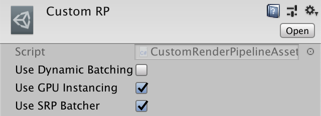
Finally, all three options are added to CustomRenderPipeline Asset as configuration fields and passed to the constructor call in createpieline:
	[SerializeField]
	bool useDynamicBatching = true, useGPUInstancing = true, useSRPBatcher = true;

	protected override RenderPipeline CreatePipeline () {
		return new CustomRenderPipeline(
			useDynamicBatching, useGPUInstancing, useSRPBatcher
		);
	}
It is now possible to change the method used by our RPs. Switching an option takes effect immediately because the Unity editor creates a new RP instance when it detects that the asset has been changed.
3.0, Transparency (Transparency)
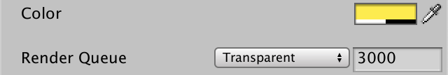
Shaders can now be used to create opaque materials for Unlit s. The alpha channel of a color, usually indicating transparency, but currently modifying it will have no effect. You can set the rendering queue to Transparent, but this only provides the order in which objects should be drawn, not how they should be drawn.
We don't need to write a separate shader to support transparent materials. With some work, our Unlit shader can support opaque and transparent rendering.
3.1, Blend Modes (Mixed Mode)
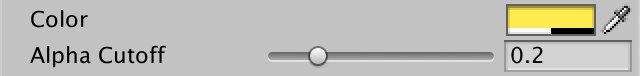
The main difference between opaque rendering and transparent rendering is whether we replace anything previously drawn or combine it with previous results to produce perspective. This can be controlled by setting the source and target blending modes. Here, the source refers to what is being drawn now, the target is what was previously drawn, and the end result. Add two shader properties for this: _ SrcBlend and _ DstBlend. They are enumerations of blend modes, and the best type we can use is Float, which sets the source to 1 and the target to zero by default:
	Properties {
		_BaseColor("Color", Color) = (1.0, 1.0, 1.0, 1.0)
		_SrcBlend ("Src Blend", Float) = 1
		_DstBlend ("Dst Blend", Float) = 0
	}
To make editing easier, we can add the Enum property to the property using a fully qualified UnityEngine. Rendering. BlendModel enumeration type as parameter:
		[Enum(UnityEngine.Rendering.BlendMode)] _SrcBlend ("Src Blend", Float) = 1
		[Enum(UnityEngine.Rendering.BlendMode)] _DstBlend ("Dst Blend", Float) = 0
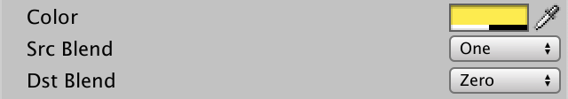
The default value indicates the opaque hybrid configuration that we have used. The source is set to 1, indicating full addition, and the target is set to zero, indicating ignorance.
The source blending mode for standard transparency is SrcAlpha, which means that the RGB component of the rendered color is multiplied by its alpha component. Therefore, the lower the alpha value, the weaker it is. Then set the target blending mode to the opposite: OneMinusSrcAlpha to achieve total weight 1
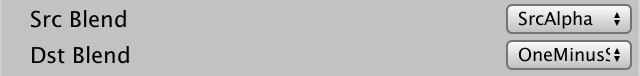
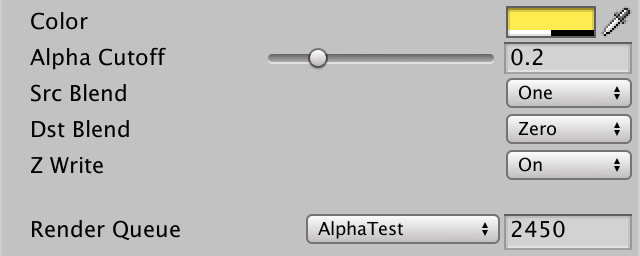
Blend statements and two modes can be used in Pass blocks to define mixed modes. To use the shader properties, you can access them by placing them in square brackets:
		Pass {
			Blend [_SrcBlend] [_DstBlend]

			HLSLPROGRAM
			...
			ENDHLSL
		}

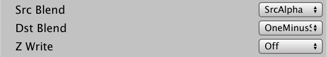
3.2, Not Writing Depth
Transparent rendering usually does not write to deep buffers because it does not benefit from it or may even produce undesired results. The ZWrite statement allows us to control whether or not to write to depth. We can use the shader property again, this time using _ ZWrite:
			Blend [_SrcBlend] [_DstBlend]
			ZWrite [_ZWrite]
Use the custom Enum(Off, 0, On, 1) property to define the shader property to create a switch with a default on value of 0 and 1:
		[Enum(UnityEngine.Rendering.BlendMode)] _SrcBlend ("Src Blend", Float) = 1
		[Enum(UnityEngine.Rendering.BlendMode)] _DstBlend ("Dst Blend", Float) = 0
		[Enum(Off, 0, On, 1)] _ZWrite ("Z Write", Float) = 1
3.3, Texturing (Texture)
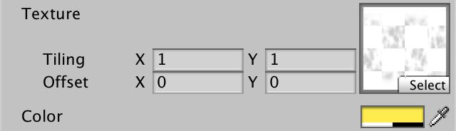
Previously, we used Alpha maps to create nonuniform translucent materials. By adding _to the shader BaseMap texture properties are also now supported. In this case, it is of type 2D, using Unity's standard white texture as the default setting, and is represented by a white string. Similarly, you must end the texture property definition with an empty code block. It was used to control texture settings a long time ago and knows that it can still be used today, primarily for compatibility, to prevent strange errors:
		_BaseMap("Texture", 2D) = "white" {}
		_BaseColor("Color", Color) = (1.0, 1.0, 1.0, 1.0)
Texture needs to be uploaded to GPU memory, which Unity will do for us. The shader requires a handle to the associated texture, and we can define it as a uniform value, except we use a macro parameter called TEXTURE2D. We also need to define a sampler state for the texture, which controls how the shader should sample, taking into account the patterns of wrap and filter. Implemented through SAMPLER macros, such as TEXTURE2D, but sampler is added before the name. Used to match the sampler status automatically provided by Unity.
Texture and sampler state are shader resources. It cannot be provided by instance and must be declared globally. In UnlitPass. Do this before the shader property in hlsl.
TEXTURE2D(_BaseMap);
SAMPLER(sampler_BaseMap);

UNITY_INSTANCING_BUFFER_START(UnityPerMaterial)
	UNITY_DEFINE_INSTANCED_PROP(float4, _BaseColor)
UNITY_INSTANCING_BUFFER_END(UnityPerMaterial)
In addition, Unity makes texture tiling and offset available by float4 with the same name as the texture property, but with _ ST, which means zooming and panning or something similar. This property is part of the UnityPerMaterial buffer, so it can be set by instance:
UNITY_INSTANCING_BUFFER_START(UnityPerMaterial)
	UNITY_DEFINE_INSTANCED_PROP(float4, _BaseMap_ST)
	UNITY_DEFINE_INSTANCED_PROP(float4, _BaseColor)
UNITY_INSTANCING_BUFFER_END(UnityPerMaterial)
To sample textures, you need the texture coordinates, which are part of the vertex properties. Specifically, we need the first pair of coordinates, or more. This is done by adding a float2 field with TEXCOORD0 meaning to the property. Since it is used for base map s, texture spatial dimensions are often named U and V, so we named it baseUV:
struct Attributes {
	float3 positionOS : POSITION;
	float2 baseUV : TEXCOORD0;
	UNITY_VERTEX_INPUT_INSTANCE_ID
};
The coordinates are passed to the fragment function because textures are sampled there. So float2 baseUV is also added to Varyings. This time, we don't need to add special meaning, just the data passed doesn't need to be of interest to the GPU. However, based on grammar, we still have to give it some meaning. So you can add any unused identifier to it, simply use VAR_BASE_UV:
struct Varyings {
	float4 positionCS : SV_POSITION;
	float2 baseUV : VAR_BASE_UV;
	UNITY_VERTEX_INPUT_INSTANCE_ID
};
When we copy coordinates in UnlitPassVertex, we can also apply storage in _ BaseMap_ scale and offset in ST. In this way, we can operate on each vertex, not on each segment. scale is stored in XY, offset in ZW, and we can access it through the swizzle property:
Varyings UnlitPassVertex (Attributes input) {
	...

	float4 baseST = UNITY_ACCESS_INSTANCED_PROP(UnityPerMaterial, _BaseMap_ST);
	output.baseUV = input.baseUV * baseST.xy + baseST.zw;
	return output;
}
UV coordinates are now available for UnlitPassFragment and interpolated across the triangle. Here, by using SAMPLE_ The TEXTURE2D macro takes texture, sampler state, and coordinates as parameters to sample texture. The final color is a texture and a single color combined by multiplication. Multiplying two vectors of the same size multiplies all matching components, so in this case, red multiplies red, green multiplies green, and so on:
float4 UnlitPassFragment (Varyings input) : SV_TARGET {
	UNITY_SETUP_INSTANCE_ID(input);
	float4 baseMap = SAMPLE_TEXTURE2D(_BaseMap, sampler_BaseMap, input.baseUV);
	float4 baseColor = UNITY_ACCESS_INSTANCED_PROP(UnityPerMaterial, _BaseColor);
	return baseMap * baseColor;
}
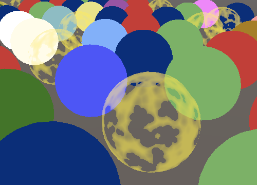
Because our texture RGB data is uniform white, the color is not affected. However, the Alpha channels are different, so the transparency is no longer consistent.
3.4, Alpha Clipping (Transparent Clipping)
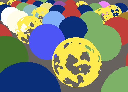
Another use of perspective surfaces is to dig holes in the surface. Shaders can also do this by discarding certain pieces that are normally rendered. But this produces hard edges instead of the smooth transition we are currently seeing. This technique is called alpha clip. A common way to do this is to define a cutoff threshold. Fragments with alpha values below this threshold will be discarded, while all other fragments will remain.
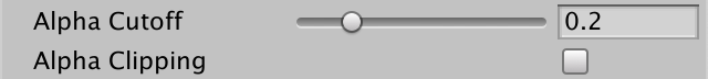
Add a _ Cutoff property, which is set to 0.5 by default. Since alpha is always between zero and one, we can use Range (0.0, 1.0) as its type:
		_BaseColor("Color", Color) = (1.0, 1.0, 1.0, 1.0)
		_Cutoff ("Alpha Cutoff", Range(0.0, 1.0)) = 0.5
Add it to UnlitPass as well. HLSL material properties:
	UNITY_DEFINE_INSTANCED_PROP(float4, _BaseColor)
	UNITY_DEFINE_INSTANCED_PROP(float, _Cutoff)
Discard the fragment by calling the clip function in UnlitPassFragment. If we pass a value of zero or less, it will abort and discard the fragment. Therefore, pass the final alpha value (accessible through the A or w attribute) minus the cutoff threshold to it:
	float4 baseMap = SAMPLE_TEXTURE2D(_BaseMap, sampler_BaseMap, input.baseUV);
	float4 baseColor = UNITY_ACCESS_INSTANCED_PROP(UnityPerMaterial, _BaseColor);
	float4 base = baseMap * baseColor;
	clip(base.a - UNITY_ACCESS_INSTANCED_PROP(UnityPerMaterial, _Cutoff));
	return base;
Material is usually chosen between transparent mixing or Alpha clipping, not both. Except for discarded fragments, the typical clip material is completely opaque and does write to the depth buffer. It uses AlphaTest to render the queue, which means it will render after all the objects that are completely opaque. This is done because discarding fragments makes some GPU optimizations impossible because triangles are no longer assumed to completely cover what follows them. First, by drawing completely opaque objects, they may eventually cover part of the alpha clipping object, saving you some hidden slices:
However, for this optimization to be effective, you must ensure that clipping is used only when required. This is achieved by adding a function to switch the shader properties. This is a Float property, set to zero by default, with a Toggle property that controls the shader keyword, and we will use _ CLIPPING. The name of the property itself does not matter, so you only need to use _ Clipping:
		_Cutoff ("Alpha Cutoff", Range(0.0, 1.0)) = 0.5
		[Toggle(_CLIPPING)] _Clipping ("Alpha Clipping", Float) = 0
3.5, Shader Features(Shader feature)
Enabling switching will _ The CLIPPING keyword is added to the list of active keywords for the material, while disabled deletes it. But that doesn't change anything alone. Unity must be told to compile different versions of the shader based on whether the keyword is defined or not. To do this, we will #pragma shader_ Feature_ CLIPPING is added to its Pass instructions:
			#pragma shader_feature _CLIPPING
			#pragma multi_compile_instancing
Now, whether negative _ CLIPPING, Unity will compile the shader code. It will produce one or two variations, depending on how we configure the material. So we can make code conditional on definition, just like protection, but in this case, we want to define _ CLIPPING includes cropping. We can use #ifdef _CLIPPING, but I prefer #if defined(_CLIPPING).
	#if defined(_CLIPPING)
		clip(base.a - UNITY_ACCESS_INSTANCED_PROP(UnityPerMaterial, _Cutoff));
	#endif
3.6, Cutoff Per Object (object-by-object cropping)
Since cutoff is part of the UnityPerMaterial buffer, it can be configured by instance. Add that functionality to PerObjectMaterialProperties. It does the same thing as color except that you need to call SetFloat on the property block instead of SetColor
	static int baseColorId = Shader.PropertyToID("_BaseColor");
	static int cutoffId = Shader.PropertyToID("_Cutoff");

	static MaterialPropertyBlock block;

	[SerializeField]
	Color baseColor = Color.white;

	[SerializeField, Range(0f, 1f)]
	float cutoff = 0.5f;

	...

	void OnValidate () {
		...
		block.SetColor(baseColorId, baseColor);
		block.SetFloat(cutoffId, cutoff);
		GetComponent<Renderer>().SetPropertyBlock(block);
	}
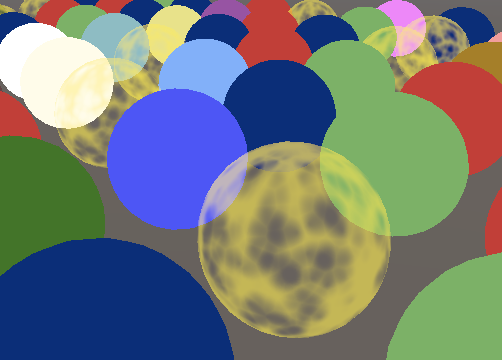
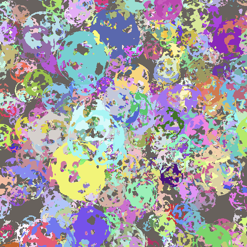
3.7, Ball of Alpha-Clipped Spheres (spherical alpha clipping)
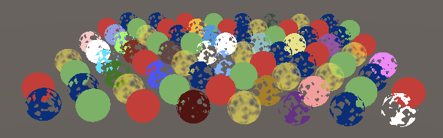
The same applies to MeshBall. Now we can use clipping material, but all the examples end up with exactly the same holes:
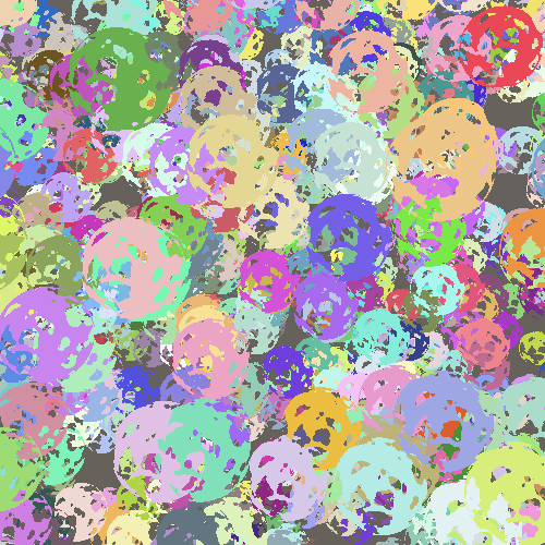
Some variation is added by giving each instance a random rotation, plus a random even scale in the range 0.5-1.5. However, instead of setting cut off for each instance, change the Alpha channel for their colors to a range of 0.5-1. Although this may result in less precise control, it can appear random
			matrices[i] = Matrix4x4.TRS(
				Random.insideUnitSphere * 10f,
				Quaternion.Euler(
					Random.value * 360f, Random.value * 360f, Random.value * 360f
				),
				Vector3.one * Random.Range(0.5f, 1.5f)
			);
			baseColors[i] =
				new Vector4(
					Random.value, Random.value, Random.value,
					Random.Range(0.5f, 1f)
				);
Note that Unity eventually sends a cutoff array to the GPU, one for each instance, even if they are the same. This value is a copy of the material, so by changing it, it can change holes in all spheres once, even if they are still different