turn https://blog.csdn.net/o83290102o5/article/details/117428173
A cube has 24 vertices and 12 triangular faces
Shader "my/jc"
{
    SubShader
    {
        Tags
        {
            "RenderType"="Opaque"
        }

        Pass
        {
            CGPROGRAM
            #pragma vertex vert
            #pragma fragment frag

            #include "UnityCG.cginc"

            struct appdata
            {
                float4 vertex : POSITION;
                float4 normal:NORMAL;
            };

            struct v2f
            {
                float4 vertex : SV_POSITION;
            };


            v2f vert(appdata v)
            {
                v2f o;
                o.vertex = UnityObjectToClipPos(v.vertex + v.normal * 0.1);

                return o;
            }

            fixed4 frag(v2f i) : SV_Target
            {
                return fixed4(1, 1, 1, 1);
            }
            ENDCG
        }
    }
}
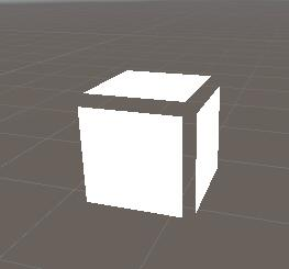
The cube has 24 vertices instead of 8 vertices, that is, at the position of each vertex of the cube, there are actually three identical vertices with vertical normals and not connected to each other. In the process of transmission, the vertex cannot be known which patch it belongs to, and each vertex is connected with 3 patches. Therefore, a vertex has 3 normals and other attributes at the same time, which requires 3 vertices to represent, which has 3 * 8 = 24 vertices.
Q: How to paste different figures on six faces of a cube
A: spm=1001.2101.3001.6650.1&utm_medium=distribute.pc_relevant.none-task-blog-2%7Edefault%7ECTRLIST%7Edefault-1.no_search_link&depth_1-utm_source=distribute.pc_relevant.none-task-blog-2%7Edefault%7ECTRLIST%7Edefault-1.no_search_link
using System.Collections;
using System.Collections.Generic;
using UnityEngine;
[ExecuteInEditMode]
public class uv : MonoBehaviour {
    MeshFilter msf;
    Mesh mesh;
    [SerializeField]
    Vector2[] uvs;
	// Use this for initialization
	void Start () {
        msf = GetComponent<MeshFilter>();
        Mesh meshCopy = Mesh.Instantiate(msf.sharedMesh) as Mesh;    // Make a deep copy
        meshCopy.name = "Cube2";
        mesh = msf.mesh = meshCopy;                                // Assign the copy to the meshes
        if (mesh == null || mesh.uv.Length != 24)
        {
            Debug.Log("Script needs to be attached to built-in cube");
            return;
        }

         uvs = mesh.uv;

        // Front
        uvs[0] =new Vector2(0.0f, 0.0f);
        uvs[1] =new Vector2(0.333f, 0.0f);
        uvs[2] =new Vector2(0.0f, 0.333f);
        uvs[3] = new Vector2(0.333f, 0.333f);

        // Top
        uvs[8] = new Vector2(0.334f, 0.0f);
        uvs[9] = new Vector2(0.666f, 0.0f);
        uvs[4] = new Vector2(0.334f, 0.333f);
        uvs[5] = new Vector2(0.666f, 0.333f);

        // Back
        uvs[10] = new Vector2(0.667f, 0.0f);
        uvs[11] = new Vector2(1.0f, 0.0f);
        uvs[6] = new Vector2(0.667f, 0.333f);
        uvs[7] = new Vector2(1.0f, 0.333f);

        // Bottom
        uvs[15] = new Vector2(0.0f, 0.333f);
        uvs[14] = new Vector2(0.333f, 0.334f);
        uvs[12] = new Vector2(0.0f, 0.666f);
        uvs[13] = new Vector2(0.333f, 0.666f);

        // Left
        uvs[19] = new Vector2(0.334f, 0.334f);
        uvs[18] = new Vector2(0.666f, 0.334f);
        uvs[16] = new Vector2(0.334f, 0.666f);
        uvs[17] = new Vector2(0.666f, 0.666f);

        // Right
        uvs[23] = new Vector2(0.667f, 0.334f);
        uvs[22] = new Vector2(1.00f, 0.334f);
        uvs[20] = new Vector2(0.667f, 0.666f);
        uvs[21] =new Vector2(1.0f, 0.666f);

        mesh.uv = uvs;
    }

}
Similar to unfolding UVs, each block of the map is assigned to each UV point
For 3D models, there are two most important coordinate systems, One is the position (X, Y, Z) coordinate of the vertex, and the other is the UV coordinate. What is UV? In short, it is the basis for mapping to the surface of the model. To be complete, it should be UVW (because XYZ has been used, it is represented by three letters). U and V are the coordinates of the picture in the horizontal and vertical directions of the display, and the values are generally 0 ~ 1, that is (the U-Th pixel / picture width in the horizontal direction and the v-th pixel / picture height in the vertical direction). What about w? The map is two-dimensional. Where are the three coordinates? Mm-hmm, the direction of W is perpendicular to the display surface. It is generally used for procedural mapping or some 3D mapping techniques (remember, there is a concept of 3D mapping!), which is not commonly used in games, so we generally call it UV for short.
All image files are two-dimensional planes. The horizontal direction is U and the vertical direction is V, through this plane, two-dimensional UV coordinate system. We can locate any pixel on the image. But a problem is how to paste this two-dimensional plane to three-dimensional NURBS and polygonal surfaces? For NURBS surfaces. Because it has UV parameters, although this UV value is used to locate the points on the surface, it is also two-dimensional, so it is easy to correspond the points on the surface to the pixels on the plane image through conversion. So it is very direct to paste images with NURBS. However, for multi deformation models, mapping becomes a troublesome thing. Therefore, in order to map the polygon, an additional UV coordinate is introduced to correspond the vertices of the polygon to the pixels on the image file, so as to locate the texture map on the polygon surface. Therefore, the vertices of a polygon have three-dimensional spatial coordinates. It also has two-dimensional UV coordinates.
UV "here refers to the abbreviation of u and V texture mapping coordinates (it is similar to the X, y and Z axes of spatial model) It defines the position information of each point on the picture These points are interconnected with the 3D model to determine the location of the surface texture map UV is to accurately map each point on the image to the surface of the model object At the gap between points, the image is interpolated smoothly by software This is called UV mapping