Original text: https://circuitdigest.com/microcontroller-projects/arduino-smart-blind-stick
Use Arduino's smart blind rod
Pass by** Aswinth Raj **January 8, 2018
Have you heard of Hugh Herr? He is a famous American rock climber who broke the limitation of disability. He firmly believes that technology can help disabled people live a normal life. In his TED speech, hull said: * human beings are not disabled. A person will never be broken. Our built environment and our technology have been damaged and disabled. Our people do not have to accept our limitations, but can transfer disability through technological innovation *. These are not just words. He also lives his own life for them. Today, he uses artificial limbs and claims to live a normal life. Therefore, yes, technology can indeed eliminate human disability. With this in mind, let's use some simple development boards and sensors to build an ultrasonic walking stick for the blind with Arduino. For people with visual impairment, its effect is not just a stick.
The smart rocker will be equipped with an ultrasonic sensor to sense the distance of any obstacle, LDR can sense lighting conditions, and an RF remote control, which can be used by the blind to remotely locate its rocker. All feedback will be provided to the blind through a buzzer. Of course, you can use vibration motor instead of buzzer and use your creativity to further improve it.

Materials required:
- Arduino Nano (available in any version)
- Ultrasonic sensor HC-SR04
- LDR
- Buzzer and LED
- 7805
- 433MHz RF transmitter and receiver
- resistor
- Capacitors
- Button
- Perforated plate
- Welding Kit
- 9V battery
You can here Purchase all necessary components of the smart shutter project.
Circuit diagram of blind rod:
This Arduino Smart Blind Stick project requires two independent circuits. The main circuit of the blind man is mounted on a stick. The other is a small remote RF transmitter circuit, which will be used to locate the main circuit. The following figure shows the circuit diagram of the main board using the ultrasonic sensor to build the blind rod:
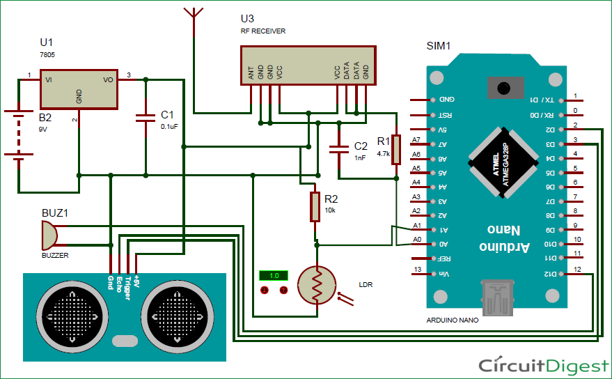
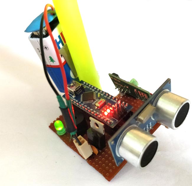
As we can see, Arduino Nano is used to control all sensors, but you can also use arduino uno to build this Smart blind bar, but follow the same pin arrangement and procedure. The whole circuit board is powered by 9V battery, which is regulated to + 5V by 7805 voltage regulator. The ultrasonic sensor is powered by 5V, and the trigger and echo pins are connected to the top of Arduino's nanotube pins 3 and 2. The LDR is connected with the value 10K of the resistor to form a voltage divider and the voltage difference is read by the ADC pin A1 of Arduino. ADC pin A0 is used to read the signal from the RF receiver. The output of the circuit board is provided by a buzzer connected to pin 12.
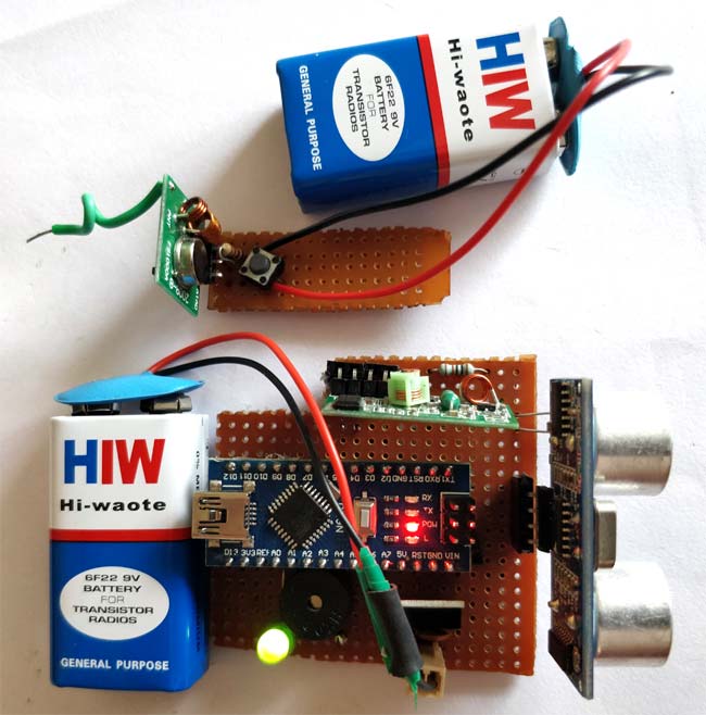
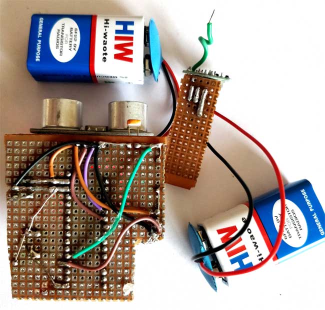
The RF remote control circuit is shown below. Its working mode will also be further explained.
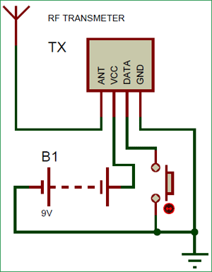
I used a trick to make this RF remote control circuit work properly. Usually, when using this 433 MHz RF module, you need one encoder and decoder or two MCU to work, just like before RF transmitter and receiver circuits are the same, We use HT12D and HT12E, decoder and encoder IC respectively. However, in our application, we only need the receiver to detect whether the transmitter is sending some signals. Therefore, the data pin of the transmitter is connected to the ground or Vcc of the power supply.
The data pin of the receiver passes through the RC filter and is then supplied to Arduino, as shown below. Now, as long as the button is pressed, the receiver will repeatedly output some constant ADC values. This repetition cannot be observed when the button is not pressed. Therefore, we wrote the Arduino program to check for duplicate values to detect whether the button was pressed. So the blind can track their stick. You can see here: How do RF transmitters and receivers work.
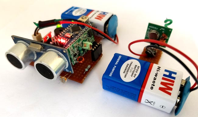
I welded all the connections with a perforated plate to keep it intact with the stick. However, you can also put them on the bread board. These are the boards I made for this blind rod project using arduino * ***
Arduino program for smart blind rods:
Once we have the hardware ready, we can connect Arduino to our computer and start programming. The complete code used on this page is located at the bottom of the page. You can upload it directly to the Arduino development board. However, if you want to know how the code works, please read further.
Like all programs, we start with * void* *setup() to initialize Input Output Pins. In our program, buzzer and trigger pins are output devices, while echo pins are input devices. We also initialized the serial monitor for debugging.
void setup()
{
Serial.begin(9600);
pinMode(Buzz,OUTPUT);
digitalWrite(Buzz,LOW);
pinMode(trigger,OUTPUT);
pinMode(echo,INPUT);
}
In the * main * cycle, we are reading all sensor data. We first read the distance data of ultrasonic sensor, light intensity of LDR and RF signal to check whether the button is pressed. All this data is stored in a variable, as shown below, for future use.
calculate_distance(trigger,echo);
Signal = analogRead(Remote);
Intens = analogRead(Light);
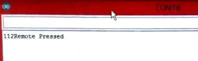
Let's first check the remote signal. We use a variable called "* like_count" * to check how many times the same value is repeated from the RF receiver. This repetition occurs only when the button is pressed. Therefore, if the count exceeds 100, we will trigger the "remote press" alarm.
//Check if Remote is pressed
int temp = analogRead(Remote);
similar_count=0;
while (Signal==temp)
{
 Signal = analogRead(Remote);
 similar_count++;
}

//If remote pressed
if (similar_count<100)
{
  Serial.print(similar_count); Serial.println("Remote Pressed");
  digitalWrite(Buzz,HIGH);delay(3000);digitalWrite(Buzz,LOW);
}
You can also check it on the serial monitor on your computer:
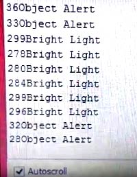
Next, we check the light intensity around the blind. If the value of LDR is less than 200, it is considered to be dark, and we warn him through the buzzer with a specific delay sound of 200ms. If the intensity is very high, more than 800, we will issue another warning. You can easily change the alarm tone and intensity by changing the corresponding values in the following codes.
//If very dark
if (Intens<200)
{
  Serial.print(Intens); Serial.println("Bright Light");
  digitalWrite(Buzz,HIGH);delay(200);digitalWrite(Buzz,LOW);delay(200);digitalWrite(Buzz,HIGH);delay(200);digitalWrite(Buzz,LOW);delay(200);
  delay(500);
}

//If very bright
if (Intens>800)
{
  Serial.print(Intens); Serial.println("Low Light");
  digitalWrite(Buzz,HIGH);delay(500);digitalWrite(Buzz,LOW);delay(500);digitalWrite(Buzz,HIGH);delay(500);digitalWrite(Buzz,LOW);delay(500);
}

Finally, we begin to measure the distance to any obstacle. If the measured distance exceeds 50 cm, no alarm will be given. However, if it is less than 50 cm, the alarm will start by beeping the buzzer. When an object approaches the buzzer, the beep interval will also be reduced. The closer the object is, the faster the buzzer will sound. This can be done by creating a delay proportional to the measured distance. Since delay () in Arduino cannot accept variables, we must use the for loop, which loops based on the measured distance, as shown below.
if (dist<50)
{
  Serial.print(dist); Serial.println("Object Alert");
  digitalWrite(Buzz,HIGH);
  for (int i=dist; i>0; i--)
    delay(10);
  digitalWrite(Buzz,LOW);
  for (int i=dist; i>0; i--)
    delay(10);
}
Know about Measurement of distance using ultrasonic sensor and Arduino More information.
By changing the values we use to compare, the program can easily fit your application. You can use the serial monitor to debug whether an error alarm is triggered. If you have any questions, you can use the comments section below to post your questions
Arduino blind action:
Finally, it's time to test our blind arduino project. Make sure that the connection is made according to the circuit diagram and the program has been uploaded successfully. Now, using a 9V battery to power both circuits, you should start to see the results. Move the ultrasonic sensor to the position close to the object, you will notice that the buzzer will sound, and the frequency of the buzzer will increase when the joystick is close to the object. If the LDR is dark or the light is too strong, the buzzer will sound. If everything is normal, the buzzer will not beep.
When you press the button on the remote control, the buzzer will give a long sound. The end of the video shows the complete work of Smart Stick for blind people using Arduino. I also use a small stick to install the whole assembly. You can use a larger stick or an actual blind stick and put it into practice.
If your buzzer always beeps, the alarm is triggered incorrectly. You can turn on the serial monitor to check the parameters and check which parameters are critical and adjust them. As usual, you can post your questions in the comments section for help. Build something that you like and want to understand.
/*
 * Program for Blind Man Stick
 * Code by B.Aswinth Raj
 * Dated: 03-11-2017
 * Website: www.circuitdigest.com
 */

const int trigger = 3; //Trigger pin of 1st Sesnor
const int echo = 2; //Echo pin of 1st Sesnor
const int Buzz = 13; //Echo pin of 1st Sesnor
const int Remote = A0; //Echo pin of 1st Sesnor
const int Light = A1; //Echo pin of 1st Sesnor

long time_taken;
int dist;
int Signal;
int Intens;
int similar_count;

void setup() {
Serial.begin(9600);
pinMode(Buzz,OUTPUT);
digitalWrite(Buzz,LOW);
pinMode(trigger, OUTPUT);
pinMode(echo, INPUT);

}

/*###Function to calculate distance###*/
void calculate_distance(int trigger, int echo)
{
digitalWrite(trigger, LOW);
delayMicroseconds(2);
digitalWrite(trigger, HIGH);
delayMicroseconds(10);
digitalWrite(trigger, LOW);

time_taken = pulseIn(echo, HIGH);
dist= time_taken*0.034/2;
if (dist>300)
dist=300;
}

void loop() { //infinite loopy
calculate_distance(trigger,echo);
Signal = analogRead(Remote);
Intens = analogRead(Light);

//Check if Remote is pressed
int temp = analogRead(Remote);
similar_count=0;
while (Signal==temp)
{
 Signal = analogRead(Remote);
 similar_count++;
}

//If remote pressed
if (similar_count<100)
{
  Serial.print(similar_count); Serial.println("Remote Pressed");
  digitalWrite(Buzz,HIGH);delay(3000);digitalWrite(Buzz,LOW);
}

//If very dark
if (Intens<200)
{
  Serial.print(Intens); Serial.println("Bright Light");
  digitalWrite(Buzz,HIGH);delay(200);digitalWrite(Buzz,LOW);delay(200);digitalWrite(Buzz,HIGH);delay(200);

  digitalWrite(Buzz,LOW);delay(200);
  delay(500);
}

//If very bright
if (Intens>800)
{
  Serial.print(Intens); Serial.println("Low Light");
  digitalWrite(Buzz,HIGH);delay(500);digitalWrite(Buzz,LOW);delay(500);digitalWrite(Buzz,HIGH);delay(500);

  digitalWrite(Buzz,LOW);delay(500);
}

if (dist<50)
{
  Serial.print(dist); Serial.println("Object Alert");

  digitalWrite(Buzz,HIGH);
  for (int i=dist; i>0; i--)
    delay(10);

  digitalWrite(Buzz,LOW);
  for (int i=dist; i>0; i--)
    delay(10);

}

//Serial.print("dist=");
//Serial.println(dist);
//Serial.print("Similar_count=");
//Serial.println(similar_count);
//Serial.print("Intens=");
//Serial.println(Intens);
}