preface
1: Driver reference from https://blog.csdn.net/BearPi/article/details/104311705.:
2: This is one of my records. I don't realize many functions. I just move a piece of video memory opened up in memory to the screen by DMA.
3: I didn't do anything during DMA handling, just gave him a delay to finish. In practical application, the semaphore should be set and the CPU should be released, and the transmission of the next frame can be started after the transmission is completed.
CUBEMX
Some GPIO, control backlight, reset, command or data
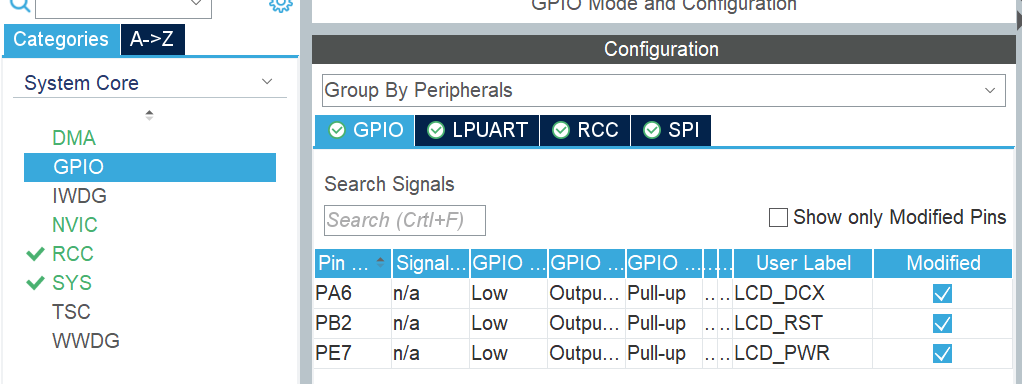
RCC is full, and the clock tree is not pasted.
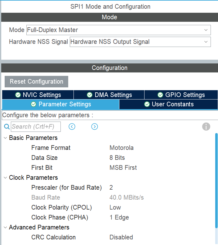
Here is SPI

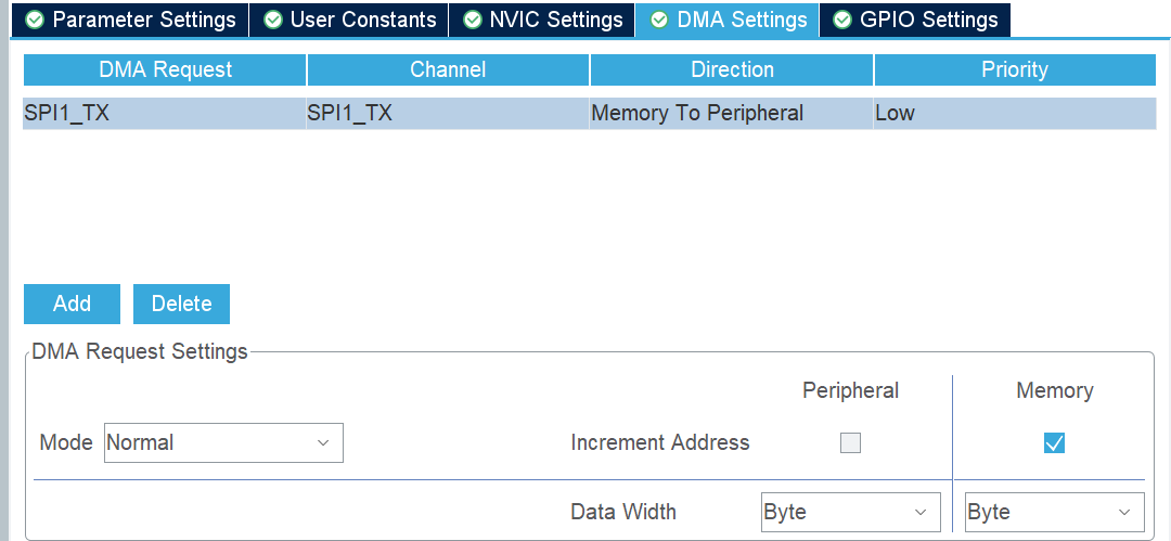
DMA
Code part
ST7789.c
#include "ST7789.h"
#include "string.h"
#include "spi.h"
#include "stdio.h"

/**
 *@brief    LCD Control pin and communication interface initialization
 *@param    none
 *@retval   none
*/
void LCD_reset(void)
{
	/* Reset LCD */
    LCD_PWR(0);
    LCD_RST(0);
    HAL_Delay(100);
    LCD_RST(1);
}
/**
 * @brief    SPI Send byte function
 * @param    TxData	Data to send
 * @param    size	Byte size of data sent
 * @return  0:Write succeeded, others: write failed
 */
uint8_t SPI_WriteByte(uint8_t *TxData,uint16_t size)
{
	return HAL_SPI_Transmit(&hspi1,TxData,size,1000);
}
/**
 * @brief   Write command to LCD
 * @param   cmd - Commands to send
 * @return  none
 */
static void LCD_Write_Cmd(uint8_t cmd)
{
    LCD_WR_RS(0);
    SPI_WriteByte(&cmd, 1);
}

/**
 * @brief   Write data to LCD
 * @param   dat - Data to be sent
 * @return  none
 */
static void LCD_Write_Data(uint8_t dat)
{
    LCD_WR_RS(1);
    SPI_WriteByte(&dat, 1);
}
/**
 * @breif   Turn on the LCD display backlight
 * @param   none
 * @return  none
 */
void LCD_DisplayOn(void)
{
    LCD_PWR(1);
}
/**
 * @brief   Turn off LCD display backlight
 * @param   none
 * @return  none
 */
void LCD_DisplayOff(void)
{
    LCD_PWR(0);
}
/**
 * @brief   Setting data writing to LCD memory area
 * @param   x1,y1	- Starting point coordinates
 * @param   x2,y2	- End coordinates
 * @return  none
 */
void LCD_Address_Set(uint16_t x1, uint16_t y1, uint16_t x2, uint16_t y2)
{
    /* Specifies the X-direction operation area */
    LCD_Write_Cmd(0x2a);
    LCD_Write_Data(x1 >> 8);
    LCD_Write_Data(x1);
    LCD_Write_Data(x2 >> 8);
    LCD_Write_Data(x2);

    /* Specify the Y direction operation area */
    LCD_Write_Cmd(0x2b);
    LCD_Write_Data(y1 >> 8);
    LCD_Write_Data(y1);
    LCD_Write_Data(y2 >> 8);
    LCD_Write_Data(y2);

    /* When this command is sent, the LCD starts waiting to receive the video memory data */
    LCD_Write_Cmd(0x2C);
}
/**
 * @brief   Clear the LCD screen in one color
 * @param   color - Clear screen color (16bit)
 * @return  none
 */
void LCD_Fill(uint16_t color)
	static uint8_t data[LCD_RAM_SIZE];
	for(uint16_t j = 0; j < Pixel_NUM; j++)
    {
        data[j * 2] = color >> 8;
        data[j * 2 + 1] =  color;
    }
    /* Specifies that the video memory operation address is full screen*/
    LCD_Address_Set(0, 0, LCD_Width - 1, LCD_Height - 1);
    LCD_WR_RS(1);/* Specify the next data as data */
	/* Write first half screen*/
	HAL_SPI_Transmit_DMA(&hspi1,data, LCD_RAM_SIZE/2);HAL_Delay(250);
	/*Write back half screen*/
	HAL_SPI_Transmit_DMA(&hspi1,data+LCD_RAM_SIZE/2, LCD_RAM_SIZE/2);HAL_Delay(250);

}

/**
 * @brief   LCD initialization
 * @param   none
 * @return  none
 */
void LCD_Init(void)
{
    /* Initialization and LCD communication pin */
    LCD_reset();
    HAL_Delay(120);

    /* Turn off sleep mode */
    LCD_Write_Cmd(0x11);
    HAL_Delay(120);

    /* Start setting video memory scanning mode, data format, etc */
    LCD_Write_Cmd(0x36);
    LCD_Write_Data(0x00);
    /* RGB 5-6-5-bit format  */
    LCD_Write_Cmd(0x3A);
    LCD_Write_Data(0x65);
    /* porch set up */
    LCD_Write_Cmd(0xB2);
    LCD_Write_Data(0x0C);
    LCD_Write_Data(0x0C);
    LCD_Write_Data(0x00);
    LCD_Write_Data(0x33);
    LCD_Write_Data(0x33);
    /* VGH set up */
    LCD_Write_Cmd(0xB7);
    LCD_Write_Data(0x72);
    /* VCOM set up */
    LCD_Write_Cmd(0xBB);
    LCD_Write_Data(0x3D);
    /* LCM set up */
    LCD_Write_Cmd(0xC0);
    LCD_Write_Data(0x2C);
    /* VDV and VRH set up */
    LCD_Write_Cmd(0xC2);
    LCD_Write_Data(0x01);
    /* VRH set up */
    LCD_Write_Cmd(0xC3);
    LCD_Write_Data(0x19);
    /* VDV set up */
    LCD_Write_Cmd(0xC4);
    LCD_Write_Data(0x20);
    /* In normal mode, the video memory rate is set to 60Mhz */
    LCD_Write_Cmd(0xC6);
    LCD_Write_Data(0x0F);
    /* Power control */
    LCD_Write_Cmd(0xD0);
    LCD_Write_Data(0xA4);
    LCD_Write_Data(0xA1);
    /* Voltage setting */
    LCD_Write_Cmd(0xE0);
    LCD_Write_Data(0xD0);
    LCD_Write_Data(0x04);
    LCD_Write_Data(0x0D);
    LCD_Write_Data(0x11);
    LCD_Write_Data(0x13);
    LCD_Write_Data(0x2B);
    LCD_Write_Data(0x3F);
    LCD_Write_Data(0x54);
    LCD_Write_Data(0x4C);
    LCD_Write_Data(0x18);
    LCD_Write_Data(0x0D);
    LCD_Write_Data(0x0B);
    LCD_Write_Data(0x1F);
    LCD_Write_Data(0x23);
    /* Voltage setting */
    LCD_Write_Cmd(0xE1);
    LCD_Write_Data(0xD0);
    LCD_Write_Data(0x04);
    LCD_Write_Data(0x0C);
    LCD_Write_Data(0x11);
    LCD_Write_Data(0x13);
    LCD_Write_Data(0x2C);
    LCD_Write_Data(0x3F);
    LCD_Write_Data(0x44);
    LCD_Write_Data(0x51);
    LCD_Write_Data(0x2F);
    LCD_Write_Data(0x1F);
    LCD_Write_Data(0x1F);
    LCD_Write_Data(0x20);
    LCD_Write_Data(0x23);
    /* Display on */
    LCD_Write_Cmd(0x21);
    LCD_Write_Cmd(0x29);

    /* The clear screen is white */
    LCD_Fill(WHITE);

    /*Open display*/
    LCD_PWR(1);
}
ST7789.h
#ifndef __ST7789_H
#define __ST7789_H
#include "main.h"
#include "spi.h"

#define	LCD_PWR(n)		(n?\
						HAL_GPIO_WritePin(LCD_PWR_GPIO_Port,LCD_PWR_Pin,GPIO_PIN_SET):\
						HAL_GPIO_WritePin(LCD_PWR_GPIO_Port,LCD_PWR_Pin,GPIO_PIN_RESET))
#define	LCD_WR_RS(n)	(n?\
						HAL_GPIO_WritePin(LCD_DCX_GPIO_Port,LCD_DCX_Pin,GPIO_PIN_SET):\
						HAL_GPIO_WritePin(LCD_DCX_GPIO_Port,LCD_DCX_Pin,GPIO_PIN_RESET))
#define	LCD_RST(n)		(n?\
						HAL_GPIO_WritePin(LCD_RST_GPIO_Port,LCD_RST_Pin,GPIO_PIN_SET):\
						HAL_GPIO_WritePin(LCD_RST_GPIO_Port,LCD_RST_Pin,GPIO_PIN_RESET))


//Definition of LCD screen resolution
#define LCD_Width   240
#define LCD_Height  240
#define LCD_RAM_SIZE LCD_Width*LCD_Height*2 		// Length 240 width 240 color depth 2bit
#define Pixel_NUM (LCD_RAM_SIZE/2)

//Color definition
#define WHITE   0xFFFF 	// white
#define YELLOW  0xFFE0 	// yellow
#Define brred 0xfc07 / / brownish red
#define PINK    0XF81F 	// Pink
#define RED     0xF800 	// gules
#Define brown 0xbc40 / / Brown
#Define gray 0x8430 / / gray
#define GBLUE   0X07FF 	// Blue
#define GREEN   0x07E0 	// green
#Define blue 0x001f / / blue
#define BLACK   0x0000 	// black

void LCD_reset(void);
void LCD_Init(void);
void LCD_Fill(uint16_t color);
#endif
main
int main(void)
{
  /* USER CODE BEGIN 1 */
	uint16_t color = 0;
  /* USER CODE END 1 */

  /* MCU Configuration--------------------------------------------------------*/

  /* Reset of all peripherals, Initializes the Flash interface and the Systick. */
  HAL_Init();

  /* USER CODE BEGIN Init */

  /* USER CODE END Init */

  /* Configure the system clock */
  SystemClock_Config();

  /* USER CODE BEGIN SysInit */

  /* USER CODE END SysInit */

  /* Initialize all configured peripherals */
	MX_GPIO_Init();
	MX_DMA_Init();
	MX_LPUART1_UART_Init();
	MX_SPI1_Init();
  /* USER CODE BEGIN 2 */
	LCD_Init();
  /* USER CODE END 2 */

  /* Infinite loop */
  /* USER CODE BEGIN WHILE */
  while (1)
  {
    /* USER CODE END WHILE */

    /* USER CODE BEGIN 3 */
	printf("working \r\n");
	color+= 0x2222;
	LCD_Fill(color);
	HAL_Delay(1000);
  }
  /* USER CODE END 3 */
}
Some explanations:
1. The project generated by cubemx does not need to manually start SPI channel or DMA transmission. The only difference between the two transmission modes is HAL_SPI_Transmit_DMA and Hal_ SPI_ The difference between the function selection of transmit.
2. Why split the upper and lower screens for transmission? Because the ram of one frame is 2402, about 100000. And Hal_ SPI_ Transmit_ The size parameter of DMA is uint16_t can only reach more than 60000, so it is necessary to break the two halves for transmission.
3. What does the main function color mean? Color is responsible for color change. color+0x2222 every second, and the screen displays the corresponding color. Color will overflow from the beginning and change color again after a period of time.
4. Why in HAL_SPI_Transmit_ Add delay after DMA?, cpu executes HAL_SPI_Transmit_ The DMA process is just a process of configuring some registers. It will not be like Hal soon_ SPI_ Like transmit, wait until the transmission is completed. Therefore, the two DMA transfers may conflict, resulting in abnormal display. You can try to reduce the delay, such as 5ms, and then look at the phenomenon.
5. How to use SPI+DMA gracefully? Set a semaphore with an initial value of 1 in Hal_ SPI_ Transmit_ It is obtained before DMA execution and released when DMA transmission is completed. It can be seen that this semaphore protects the two processes of DMA configuration and transmission. In addition, you need to turn on DMA interrupt.