Reprint: http://www.cnblogs.com/ListenFly/archive/2013/06/12/3114047.html
This paper mainly explains the basic graphics knowledge in WPF, as follows:
1. Basic knowledge preparation of graphics
2. Graphics architecture in WPF
3. Color and brush
4. Shape
5. Drawing and Visual
1.1 coordinates in WPF
1.1. 1. Default coordinates of WPF: the plane coordinate system in WPF mainly includes the origin position, X and Y axis directions, and coordinate units. The default coordinate system origin position of WPF is in the upper left corner of the drawing area. The X axis increases to the right and the Y axis increases downward.
Custom coordinate system: the custom coordinate system is mainly implemented through the Transform class. Generally, ScaleTransform and TranslateTransform can be used for coordinate inversion and horizontal movement, as follows:

 <Canvas>
        <Canvas.RenderTransform>
            <TransformGroup>
                <ScaleTransform ScaleY="-1"></ScaleTransform>
                <TranslateTransform Y="200"></TranslateTransform>
            </TransformGroup>
        </Canvas.RenderTransform>
        <Line X1="0" Y1="0" X2="100" Y2="100"   Stroke="Red" StrokeThickness="2"></Line>
        <Button Canvas.Top="100" Canvas.Left="120" Foreground="Green" Content="Test Button" FontSize="14"></Button>
    </Canvas>
The above code is a simple example of customizing coordinates. Generally speaking, Canvas will be used for drawing graphics, because Canvas can specify relative Top and Left. In the code, RenderTransform determines the effect of the coordinate system. Use ScaleTransform to change the positive direction of the Y axis from down to up (because ScaleY is - 1, it is opposite to the previous one), and TranslateTransform moves the origin down 200 The effects are as follows:
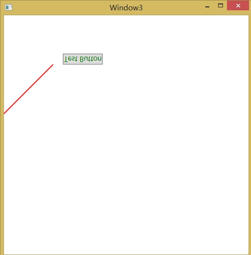
It can be seen that the starting position of the straight line is 200 down. There is still a problem. After flipping, the text of the button is also inverted. Therefore, add a conversion to the button, that is, add the following code to the button:
            <Button.RenderTransform>
                <ScaleTransform ScaleY="-1"></ScaleTransform>
            </Button.RenderTransform>
1.1. Object transformation in 2wpf
Transform has been mentioned before. Of course, the type of transform is not just the above two types. The transform objects in WPF inherit from the type transform as follows:
TranslateTransform translation transformation, X and Y represent the translation amount on the x-axis and y-axis;
RotateTransform rotation transformation, Angle represents the rotation Angle, CenterX and CenterY represent the center coordinates of rotation;
ScaleTransform scaling transformation, ScaleX and ScaleY represent the scaling scale on the X-axis and Y-axis. Of course, flipping like the above example is ok, and CenterX and CenterY represent the origin coordinates of scaling;
SkewTransform is a skew transform (which can also be a twist transform). AngleX and AngleY represent the angle of the skew, and CenterX and CenterY represent the origin of the skew;
MatrixTransform matrix transformation;
TransformGroup when performing multiple transformations on an element, you can set multiple transformations through TransformGroup to realize combined transformation. Here, remember that the effects of transformations in different orders are completely different. (one of the important reasons for the order is that transformations such as rotation and scaling are performed at the origin of the coordinate system. Scaling an object centered at the origin is different from scaling an object that has left the origin. Similarly, rotating an object centered at the origin is different from rotating an object that has left the origin.)
It seems that I don't understand. I also use the example just now. In the previous example, there are two transforms, ScaleTransform and TranslateTransform. Our order is also the former and the latter. The effect is normal. If we modify it as follows:
            <TransformGroup>
                <TranslateTransform Y="200"></TranslateTransform>
                <ScaleTransform ScaleY="-1"></ScaleTransform>
            </TransformGroup>
At this time, you will find that everything is gone and the whole form is blank. The reason is the problem of coordinates. Listen to me. As the red font mentioned earlier, scaling is based on the origin. We move the Canvas down 200, and the origin is the upper left corner (0,0), so the rotation effect is actually outside the scope of the Canvas, so we can't see any elements. To solve this problem, it is also very simple to set the center of ScaleTransform, that is, the origin center, as shown in the following code:
            <TransformGroup>
                <TranslateTransform Y="200"></TranslateTransform>
                <ScaleTransform ScaleY="-1" CenterY="200"></ScaleTransform>
            </TransformGroup>
In this way, the effect we see is the same as that we saw before. That is because we move the central origin of ScaleTransform down the Y axis by 200, which is still the upper left corner (0,0) of the Canvas.
1.2 graphics architecture of WPF
1.2. 1 the two-dimensional graphics architecture of WPF starts from logical tree and visual tree.
The structure of XAML file is a tree structure, which is expanded layer by layer from a root node. This tree is a "logical tree". Each node in the tree is a complete and independent element. WPF provides methods to traverse logical and visual trees, namely LogicTreeHelper and visual treehelper.
Difference between logical tree and visual tree:
(1) The hierarchical structure of logical tree is similar to that of XAML file, while the Visual tree and other nodes must inherit from Visual and Visual3D;
(2) Logical trees are mainly used in the following aspects.
Resource search: if a brush resource is added to an element, it will be searched up layer by layer according to the nodes of the logical tree to the root node of the logical tree;
Attribute value inheritance: for example, if the font size of a form is set, the nodes below it will be affected in turn according to the hierarchy of the logical tree. If a node does not have a font size attribute, it will pass through the node and affect the following logical nodes containing this attribute. (for example, if the attribute FontSize of the Window tag is set, the logical nodes under it will be affected.)
(3) The visual tree is mainly used to describe the appearance of the user interface. You can modify the visual tree of the control by customizing the control template, so as to change the appearance of the control.
1.2. 2 important elements in WPF 2D graphics
(1)Visual
Visual tree is the basis of WPF rendering. Without visual 3D, the whole graphical user interface is composed of visual. That is, the derived classes of visual constitute the visual tree, and WPF renders the visual tree from the root node. Visual is mainly used to support WPF drawing.
(2)Drawing
Visual can be imagined as a window, so the contents drawn in the window are handed over to drawing for description. Drawing derives the following different drawing methods for vectors, images, text and even video.
One. GeometryDrawing: draws a collection drawing.
II. ImageDrawing: draws an image.
Three. GlyphRunDrawing: draws text.
Four. Viedo drawing: play audio and video files.
Five. DrawingGroup: a collection of Drawing.
The method GetDrawing in VisualTreeHelper obtains the Drawing collection from Visual. The input parameter is a Visual and the return value is a DrawingGroup.
(3)Geometry
When drawing geometry, GeometryDrawing needs geometric data, and then sets the brush and brush to draw. This geometric data is described by geometry and its derivatives. Geometry is only used to describe the data of two-dimensional graphics and is not responsible for display. The derived classes include geometric graphics such as ellipses, rectangles and lines.
(4)Shape
Is an advanced graphic element derived from FrameworkElement, so it can abscond in controls or containers at will.
(5) relationship among the four
One. Each node of WPF's Visual tree is derived from Visual;
II. Shape and Visual are inherited relationships.
Visual <-- UIElement <-- FrameworkElement <-- Shape;
Three. The Drawing content of Visual is described by Drawing. A DrawingGroup can be obtained from a Visual through the static method GetDrawing of VisualTreeHelper. Thus, you can traverse all Drawing objects in Visual;
Four. A derived class of Drawing, GeometryDrawing, needs to use Geometry to describe its geometric data;
Five. Shape is derived from Visual and therefore has a relationship between Visual and Drawing. And the shape has a Fill attribute, which can be associated through DrawingBrush and Drawing;
Six. Path is associated with Geometry through a Data property.
1.3 color and brush
1.3. 1 color in WPF
In addition to using the Colors enumeration to access the Colors in WPF, you can also specify any color through the a (transparent value), R, G and B (three primary Colors) attributes.

            Color color = new Color();
            //Set to red
            color = Color.FromRgb(255, 0, 0);
            //Set to translucent red
            color = Color.FromArgb(100, 255, 0, 0);
            //Assign values to colors in string format "#aarrggbb" The first two digits are transparency A, followed by R, G and B, and need to be represented by hexadecimal values
            color = (Color)ColorConverter.ConvertFromString("#FFFF0000");
1.3. 2 brush
There are 6 brushes in WPF:
(1) SolidColorBrush: monochrome or solid color brush;
(2) LinearGradientBrush: a linear gradient brush, which connects two points into a line segment by specifying two points, linearly interpolates the color between the two points, and then performs gradient filling;
(3) RadialGradientBrush: a diffuse gradient brush, which is different from the LinearGradientBrush gradient, and emits outward in an elliptical shape;
(4) ImageBrush: picture brush to fill the picture into the control area;
(5) DrawingBrush: a graphic brush, which draws geometric figures, images, text and even videos through Drawing, and can also form more complex figures, and finally fill these figures into the control area;
(6) VisualBrush: use Visual objects to fill the target area. All controls are derived from Visual, so you can fill all controls into the area, but VisualBrush only draws the appearance of Visual, and the {button of the filled area cannot be clicked.
LinearGradientBrush:

    <Grid>
        <Grid.Background>
            <LinearGradientBrush>
                <GradientStop Color="Red" Offset="0"></GradientStop>
                <GradientStop Color="Blue" Offset="1"></GradientStop>
            </LinearGradientBrush>
        </Grid.Background>
    </Grid>
LinearGradientBrush generally requires two or more Color objects and two Point objects, i.e. Offset value. The Color filling is connected into a line segment from the first Point to the last Point. The filling Color of the gradient is related to the value of the Point. The center Point of the filled line segment is at the center of the two points, The first GradientStop Color is also a gradient from the initial Offset to the last GradientStop Color, filled with interpolation in the middle
LinearGradientBrush has a StartPoint start position and an EndPoint end position. By default, StartPoint is (0,0) and EndPoint is (1,1). If the start position is not in the upper left corner (0,0) and the end position is not in the lower right corner (1,1), some of them exceed the range of start point and end point. The gradient brush provides the SpreadMethod attribute (applicable to LinearGradientBrush and RadialGradientBrush). There are three optional values (pad, reflect and repeat). See the following figure for the difference between the three values:
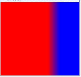
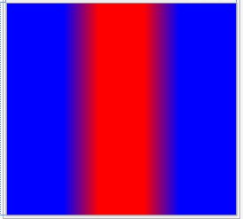
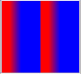
The three figures are the effects corresponding to the attribute values of pad, reflect and repeat. Pad should have no change. Reflect is reflected, that is, the colors on the left and right are symmetrical, and the third is repeated display.
RadialGradientBrush:
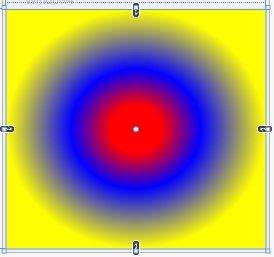
RadialGradientBrush emits gradients outward in an elliptical shape with a starting point, and shares the attributes of GradientBrush with LinearGradientBrush. RadialGradientBrush is determined by the attributes center, GradientOrigin, RadiusX and RadiusY. Center represents the center position of the filling ellipse, and the relative coordinates are (0.5,0.5) by default. GradientOrigin represents the source point of the gradient. The default values of relative coordinates are (0.5,0.5), that is, the default values of GradientOrigin and Center overlap; The radius of RadiusX and RadiusY ellipses is 0.5, which means that the long and short radius of the ellipse is half the length and width of the filled area by default.

<Grid>
        <Grid.Background>
            <RadialGradientBrush SpreadMethod="Pad">
                <GradientStop Color="Red" Offset="0.2"></GradientStop>
                <GradientStop Color="Blue" Offset="0.5"></GradientStop>
                <GradientStop Color="Yellow" Offset="1"></GradientStop>
            </RadialGradientBrush>
        </Grid.Background>
    </Grid>
Tile brush: (imagebrush, drawingbrush and visualbrush are all derived from tile brush)
TileBrush can fill the target area with repeated patterns, which can be Image, Visual or Drawing. The brush content is determined by different types of brushes. ImageBrush specifies the brush content through ImageSource; DrawingBrush is specified through the Drawing attribute; VisualBrush is specified through the Visual properties.
Properties of TileBrush:
Stretch attribute: there are four enumeration values None, Fill, Uniform and UniformToFill.
None, the picture will be cut. The reduced area can be determined through AlignmentX and AlignmentY;

<StackPanel Orientation="Horizontal">
            <Rectangle Width="200" Height="200">
                <Rectangle.Fill>
                    <ImageBrush  ImageSource="1.jpg" Stretch="None"></ImageBrush>
                </Rectangle.Fill>
            </Rectangle>
            <Rectangle Width="200" Height="200">
                <Rectangle.Fill>
                    <ImageBrush  ImageSource="1.jpg" Stretch="None" AlignmentX="Center" AlignmentY="Top"></ImageBrush>
                </Rectangle.Fill>
            </Rectangle>
            <Rectangle Width="200" Height="200">
                <Rectangle.Fill>
                    <ImageBrush  ImageSource="1.jpg" Stretch="None" AlignmentX="Center" AlignmentY="Bottom"></ImageBrush>
                </Rectangle.Fill>
            </Rectangle>
        </StackPanel>
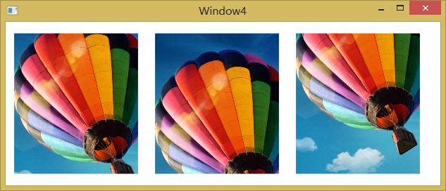
Uniform, the picture is scaled. The length and segment degree of the picture depend on the minimum value of the area (i.e. the small one of Height and Width).

 <StackPanel Orientation="Horizontal">
                <Rectangle Width="50" Height="300">
                    <Rectangle.Fill>
                        <ImageBrush  ImageSource="1.jpg" Stretch="Uniform"></ImageBrush>
                    </Rectangle.Fill>
                </Rectangle>
                <Rectangle Width="100" Height="300">
                    <Rectangle.Fill>
                        <ImageBrush  ImageSource="1.jpg" Stretch="Uniform" ></ImageBrush>
                    </Rectangle.Fill>
                </Rectangle>
                <Rectangle Width="200" Height="300">
                    <Rectangle.Fill>
                        <ImageBrush  ImageSource="1.jpg" Stretch="Uniform" ></ImageBrush>
                    </Rectangle.Fill>
                </Rectangle>
            </StackPanel>
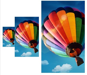
You can see that the Height of the picture depends on the small value of rectangle's Height and Width. (when the value depends on Height, then AlignmentY is valid, and when the value depends on Width, then only AlignmentX is valid.)
UniformToFill, first consider the fully filled area, and then consider the scaling of the scale. (by cutting the image, the image is completely filled into the area, and the excess part is cut. In the final analysis, the image value is determined according to the large value of Height and Width.)

  <StackPanel Orientation="Horizontal" Margin="10">
                <Rectangle Width="50" Height="300">
                    <Rectangle.Fill>
                        <ImageBrush  ImageSource="1.jpg" Stretch="UniformToFill"></ImageBrush>
                    </Rectangle.Fill>
                </Rectangle>
                <Rectangle Width="100" Height="300">
                    <Rectangle.Fill>
                        <ImageBrush  ImageSource="1.jpg" Stretch="UniformToFill" ></ImageBrush>
                    </Rectangle.Fill>
                </Rectangle>
                <Rectangle Width="200" Height="300">
                    <Rectangle.Fill>
                        <ImageBrush  ImageSource="1.jpg" Stretch="UniformToFill" ></ImageBrush>
                    </Rectangle.Fill>
                </Rectangle>
            </StackPanel>
        </StackPanel>
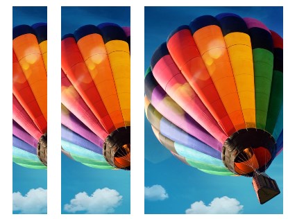
As you can see, the area beyond the picture has been cut.
ViewBox property: Specifies the brush content displayed to the area. It is a Rect type, which can use relative and absolute coordinates, which is specified by the ViweboxUnits property. The relative coordinates are still the upper left corner (0,0) and the lower right corner (1,1) The default value is (0,0,1,1), which shows all the contents. If the ViewBox is (0,0,0.5,0.5), it means that the upper left corner is displayed to the area.
Viewport property: it is a Rect type that specifies which part of the target area Brush is mapped to. Relative and absolute coordinates can be used, which is specified by the ViweboxUnits property. If the value of viewport is (0,0,0.5,0.5) and the TileMode property is None, the target area has only the upper left corner
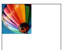
TileMode: describes how Brush fills the target area. The enumeration values are as follows.
None: do not repeat filling.
Tile: repeat fill.
FlipX: flips the fill of Brush interlaced columns on the horizontal axis.
Flip: flip the Brush interlaced fill on the vertical axis.
FlipXY: flip the fill of Brush interlaced rows and columns in two directions.

   <StackPanel Orientation="Horizontal" Margin="10">
                <Rectangle Width="200" Height="200"  Stroke="Black" StrokeThickness="1">
                    <Rectangle.Fill>
                        <ImageBrush  ImageSource="1.jpg" Stretch="UniformToFill"  Viewport="0,0,0.5,0.5" TileMode="None"></ImageBrush>
                    </Rectangle.Fill>
                </Rectangle>
                <Rectangle Width="200" Height="200"  Stroke="Black" StrokeThickness="1" Margin="5">
                    <Rectangle.Fill>
                        <ImageBrush  ImageSource="1.jpg" Stretch="UniformToFill"  Viewport="0,0,0.5,0.5" TileMode="Tile"></ImageBrush>
                    </Rectangle.Fill>
                </Rectangle>
                <Rectangle Width="200" Height="200"  Stroke="Black" StrokeThickness="1" Margin="5">
                    <Rectangle.Fill>
                        <ImageBrush  ImageSource="1.jpg" Stretch="UniformToFill"  Viewport="0,0,0.5,0.5" TileMode="FlipX"></ImageBrush>
                    </Rectangle.Fill>
                </Rectangle>
                <Rectangle Width="200" Height="200"  Stroke="Black" StrokeThickness="1" Margin="5">
                    <Rectangle.Fill>
                        <ImageBrush  ImageSource="1.jpg" Stretch="UniformToFill"  Viewport="0,0,0.5,0.5" TileMode="FlipY"></ImageBrush>
                    </Rectangle.Fill>
                </Rectangle>
                <Rectangle Width="200" Height="200"  Stroke="Black" StrokeThickness="1" Margin="5">
                    <Rectangle.Fill>
                        <ImageBrush  ImageSource="1.jpg" Stretch="UniformToFill"  Viewport="0,0,0.5,0.5" TileMode="FlipXY"></ImageBrush>
                    </Rectangle.Fill>
                </Rectangle>
            </StackPanel>

The five figures are none, tile, flipx, flipy and flipxy
Create a special effect with Brush:

 <Grid >
        <Grid.RowDefinitions>
            <RowDefinition></RowDefinition>
            <RowDefinition></RowDefinition>
        </Grid.RowDefinitions>
        <Image x:Name="imgVisual" Grid.Row="0" Source="1.jpg" Height="300" Width="200" Stretch="Fill"></Image>
        <Rectangle Grid.Row="1" Width="{Binding ActualWidth,ElementName=imgVisual}" Height="{Binding ActualHeight,ElementName=imgVisual}">
            <Rectangle.Fill>
                <VisualBrush Visual="{Binding ElementName=imgVisual}">
                    <VisualBrush.RelativeTransform>
                        <ScaleTransform ScaleX="1" ScaleY="-1" CenterX="0.5" CenterY="0.5"></ScaleTransform>
                    </VisualBrush.RelativeTransform>
                </VisualBrush>
            </Rectangle.Fill>
            <Rectangle.OpacityMask>
                <LinearGradientBrush StartPoint="0,0" EndPoint="0,0.5">
                    <GradientStop Offset="0" Color="Red"></GradientStop>
                    <GradientStop Offset="0.5" Color="Blue"></GradientStop>
                    <GradientStop Offset="1" Color="Transparent"></GradientStop>
                </LinearGradientBrush>
            </Rectangle.OpacityMask>
        </Rectangle>
    </Grid>

The effect of reflection is realized.
1.4 Shape
1.4. 1 rectangle
<Rectangle Height="200" Width="200" Fill="Yellow"></Rectangle>
Rectangle sets the Height and Width by specifying Height and Width. In addition, rectangle can also realize rounded rectangle, as follows:
<Rectangle Width="200" Height="200" RadiusX="50" RadiusY="50" Fill="Yellow"></Rectangle>
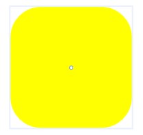
Specify the x-axis radius of the ellipse that rounds the corners of the rectangle by specifying RadiusX, and the y-axis radius of the ellipse that rounds the corners of the rectangle by specifying RadiusY
1.4. 2 ellipse
<Ellipse Width="200" Height="200" Fill="Yellow"></Ellipse>
In addition to the Height and Width attributes of and Rectangle, they also have stroke (set border color) and strokethickness (set border Width)
1.4. 3 line
<Line X1="10" X2="100" Y1="10" Y2="100" Stroke="Black" StrokeThickness="2"></Line>
Line has four attributes x1, X2, Y1 and Y2 to identify the coordinates of two points. In addition, it also has Stroke and StrokeThickness.
1.4.4 Polyline and polygon (segment)
Polyline:
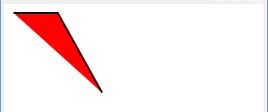
<Polyline Points="10,10 60,10 110,100" Stroke="Black" StrokeThickness="2" Fill="Red"></Polyline>
Polygon:
<Polygon Points="10,10 60,10 110,100" Stroke="Black" StrokeThickness="2" Fill="Red"></Polygon>

Polyline and Polygon use the Points(Point type) attribute to represent a group of line segments. The difference between the two is that the latter automatically adds a line from the first point to the last point.
1.4. 5 line type, line cap, line connection and filling rules
1.4. 5.1 line type
Linetype is controlled by two attributes, StrokeDashArray and StrokeDashOffset. The StrokeDashArray type is a collection of double types. Set a string of double values to describe the linetype. If it is set to "4,3", it means to fill 4 cells (the width of the line, i.e. controlled by the StrokeThickness attribute), then empty 3 cells and cycle on; If it is set to "4,1,3", it means that 4 single eaves are filled, 1 cell is empty, and then 3 cells are filled, cycling in turn. StrokeDashOffset describes the starting position of the linetype. If StrokeDashArray is set to (4,3) and StrokeDashOffset is set to 2, it means that the first segment of the line segment is filled with only 2 cells (4-2), 3 cells are empty, and then 4 cells are filled to continue the cycle.
   <Line X1="10" X2="300" Y1="30" Y2="30" Stroke="Black" StrokeThickness="2" StrokeDashArray="2,3" ></Line>
   <Line X1="10" X2="300" Y1="40" Y2="40" Stroke="Black" StrokeThickness="3" StrokeDashArray="2,3" ></Line>
   <Line X1="10" X2="300" Y1="50" Y2="50" Stroke="Black" StrokeThickness="3" StrokeDashArray="2,3,1" ></Line>

Set StrokeDashOffset:
   <Line X1="10" X2="300" Y1="30" Y2="30" Stroke="Black" StrokeThickness="2" StrokeDashArray="2,3"  StrokeDashOffset="2"></Line>
   <Line X1="10" X2="300" Y1="40" Y2="40" Stroke="Black" StrokeThickness="3" StrokeDashArray="2,3"  StrokeDashOffset="1"></Line>
   <Line X1="10" X2="300" Y1="50" Y2="50" Stroke="Black" StrokeThickness="3" StrokeDashArray="2,3,1" StrokeDashOffset="10" ></Line>

1.4. 5.2 wire cap
Both ends of the line can be set with StrokeStartLineCap and StrokeEndLineCap. There are four kinds of line caps in WPF: Flat (Flat cap, default), Square (Square cap), round (round cap) and triangle (sharp cap); The difference between Square and Flat is that Square takes half of the line width at both ends of the line segment as the Square cap. StrokeDashCap controls the line caps at both ends of each small segment inside the segment, which is invalid for both ends of the segment.
     <Line X1="30" X2="300" Y1="30" Y2="30" Stroke="Black" StrokeThickness="10" StrokeStartLineCap="Round" StrokeEndLineCap="Triangle" ></Line>
     <Line X1="30" X2="300" Y1="30" Y2="30" Stroke="Black" StrokeThickness="10"  StrokeEndLineCap="Triangle" ></Line>
     <Line X1="30" X2="300" Y1="30" Y2="30" Stroke="Black" StrokeThickness="10" StrokeStartLineCap="Square" StrokeEndLineCap="Triangle" ></Line>
1.4. 5.3 wire connection
The connection of lines is controlled by the StrokeLineJoin attribute. There are three methods in WPF: miter (sharp corner, default), bevel (flat corner), and round (round)
   <Polyline Points="10,40 30,10 50,60 70,10 " Stroke="Black"  StrokeThickness="10" StrokeLineJoin="Miter"></Polyline>
   <Polyline Points="10,40 30,10 50,60 70,10 " Stroke="Black"  StrokeThickness="10" StrokeLineJoin="Bevel"></Polyline>
   <Polyline Points="10,40 30,10 50,60 70,10 " Stroke="Black"  StrokeThickness="10" StrokeLineJoin="Round"></Polyline>
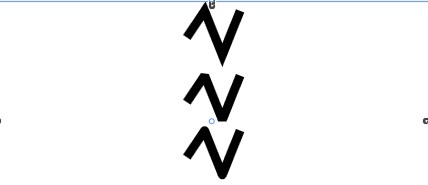
In addition, there is an attribute StrokeMiterLimit, which is used to control the length of sharp corners and prevent sharp corners from being too long due to too small angles. This value is greater than or equal to 1. It describes the maximum ratio of sharp corner length to half of line width, that is, the longest sharp corner length cannot exceed 0.5 x StrokeThickness x StrokeMiterLimit. The default value of StrokeMiterLimit is 10
1.4. 5.4 filling rules
By setting the FillRule attribute, only Polyline and Polygon shapes have this attribute, which has two values, EvenOdd and NonZero.
The EvenOdd enumeration value determines whether a point on the shape is "inside". It draws an infinite ray in any direction from the point, and then calculates the number of path segments formed by the intersection of the ray in the specified shape. If the number is odd, the point is inside; If the number is even, the point is external.
The Nonzero} enumeration value determines whether a point on the shape is "inside". It draws an infinite ray in any direction from the point, and then checks the intersection of the shape segment and the ray. The {count starts from zero, increases by 1 whenever the segment crosses the ray from left to right, and decreases by 1 whenever the path segment crosses the ray from right to left. After calculating the number of intersections, if the result is zero, the point is outside the path. Otherwise, it is inside the path.
Note: refer to MSDN for detailed explanation( help)
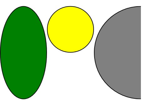
1.4. 6 adjust Shape size (Strecth setting)
Strecth is still four none, fill, uniform and uniformtofill. Please refer to the above for specific explanation. example:

  <StackPanel Orientation="Horizontal">
            <Grid Height="300" Width=" 150">
                <Ellipse Stroke="Black" StrokeThickness="2" Stretch="Fill" Fill="Green"></Ellipse>
            </Grid>
            <Grid Height="300" Width=" 150">
                <Ellipse Stroke="Black" StrokeThickness="2" Stretch="Uniform" Fill="Yellow"></Ellipse>
            </Grid>
            <Grid Height="300" Width=" 150">
                <Ellipse Stroke="Black" StrokeThickness="2" Stretch="UniformToFill" Fill="Gray"></Ellipse>
            </Grid>
   </StackPanel>
1.5 Drawing and Visual
1.5.1 Drawing includes all the information to be drawn, such as geometry, brush and brush. It can draw not only geometric shapes, but also images, text and even video.
Drawing derived class:
GeometryDrawing drawing Geometry: describing Geometry
Brush: describes how to fill
Pen: describes how to fill an external contour line
ImageDrawing draw image ImageSource: Specifies the path of the image file
Rect: Specifies the location of the image file
VideoDrawing Player: media Player
Rect: Specifies the location of the media player
GlyphRunDrawing draw text GlyphRun: information describing the text to be drawn
ForegroundBrush: Specifies the foreground color
DrawingGroup is a collection of Drawing, similar to GeometryGrop Children: specify the sub objects under the collection
Note: Drawing is not an element, so it cannot be directly placed in the interface. The use method is as follows:
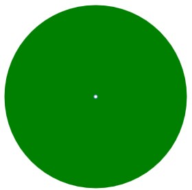
(1) Put Drawing in DrawingImage, which is generally used as the attribute of Image.

        <Image Height="300" Width="300">
            <Image.Source>
                <DrawingImage>
                    <DrawingImage.Drawing>
                        <DrawingGroup>
                            <GeometryDrawing Brush="Green">
                                <GeometryDrawing.Geometry>
                                    <EllipseGeometry RadiusX="50" RadiusY="50"> </EllipseGeometry>
                                </GeometryDrawing.Geometry>
                            </GeometryDrawing>
                        </DrawingGroup>
                    </DrawingImage.Drawing>
                </DrawingImage>
            </Image.Source>
        </Image>
(2) Place Drawing in the DrawingBrush class, which derives from Brush.

        <Button Height="30" Width="200">
            <Button.Background>
                <DrawingBrush>
                    <DrawingBrush.Drawing>
                        <DrawingGroup>
                            <GeometryDrawing Brush="Red">
                                <GeometryDrawing.Geometry>
                                    <EllipseGeometry RadiusX="10" RadiusY="10"></EllipseGeometry>
                                </GeometryDrawing.Geometry>
                            </GeometryDrawing>
                        </DrawingGroup>
                    </DrawingBrush.Drawing>
                </DrawingBrush>
            </Button.Background>
        </Button>

(3) put Drawing in DrawingVisual.
(4) use Drawing to unify graphics and videos.

        <Rectangle>
            <Rectangle.Fill>
                <DrawingBrush>
                    <DrawingBrush.Drawing>
                        <DrawingGroup>
                            <VideoDrawing></VideoDrawing>
                            <ImageDrawing></ImageDrawing>
                        </DrawingGroup>
                    </DrawingBrush.Drawing>
                </DrawingBrush>
            </Rectangle.Fill>
        </Rectangle>
1.5.2 Visual
WPF introduces the DrawingVisual class, which only retains the necessary features for rendering, such as transparency and clipping. At the same time, because DrawingVisual derives from Visual, the hit test behavior is retained.
1.5.2.1 DrawingVisual and DrawingContext
DrawingVisual cannot directly set the Drawing property in XAML, so it needs DrawingContext to draw Drawing.

            FormattedText text = new FormattedText("Listenfly",new System.Globalization.CultureInfo("en-us"),FlowDirection.LeftToRight,
                                                    new Typeface(this.FontFamily,FontStyles.Normal,FontWeights.Normal,new FontStretch()),this.FontSize,this.Foreground);

            DrawingVisual drawingVisual = new DrawingVisual();
            DrawingContext drawingContext = drawingVisual.RenderOpen();
            drawingContext.DrawText(text,new Point(2,2));
            drawingContext.Close();

            RenderTargetBitmap bmp = new RenderTargetBitmap(200, 20, 120, 100, PixelFormats.Pbgra32);
            bmp.Render(drawingVisual);
            img.Source = bmp;
Write text through the DrawText of DrawingContext. The DrawingContext is obtained through the RenderOpen method of DrawingVisual. Finally, call the Close method to Close.
Draw a rabbit with Visual (from WPF sunflower Dictionary):

  <Application.Resources>
        <SolidColorBrush x:Key="headcolor" Color="#FFC9CACA"/>
        <!--Second rabbit head-->
        <PathGeometry x:Key="geometryhead2" Figures="M136.75,142.11L130.298,147.411L130.798,159.911L133.798,173.411L146.298,199.911L150.798,206.911L157.798,207.411L193.298,205.411L199.298,202.911L210.798,198.911L212.798,191.411L217.298,167.911L215.798,144.911L212.798,134.411L203.298,130.911L184.298,129.411L168.798,130.911L156.298,133.411L136.75,142.11z"/>
        <PathGeometry x:Key="geometryear2" Figures="M140.5,140.11L127.5,117.61L126.5,112.11L132.5,105.11L136,102.61L142.5,101.61L145.5,105.11L156.5,132.61L140.5,140.11
                      M184.5,128.61L184.5,101.11L186.5,99.11L193.5,96.61L202,98.61L206,101.11L204,114.11L203.5,130.11L184.5,128.61z"/>
        <PathGeometry x:Key="geometryeyeorbit2" Figures="M142.5,171.11L142.25,172.61L148,177.86L157,180.61C157,180.61,162,181.61,162,180.86C162,180.11,169.5,175.61,169.5,175.61L174,169.86L171.25,157.61L142.5,171.11
                      M174,168.86L181.5,173.61L184,174.11L196.75,174.86L199.5,173.11L204.25,168.11L206.25,161.11L207.25,157.11L181,157.508L174.25,157.61L171.25,156.61L174,168.86z"/>
        <PathGeometry x:Key="geometryeyelid2" Figures="M142.25,150.36L139.75,154.36L138.25,164.11L140.25,170.36L142.5,171.11L150.25,168.61L158.75,164.61L165,160.86L168.5,159.61L171.25,157.61L171,149.61L166,145.36L161,143.86L153.5,143.36L145.75,147.11L142.25,150.36
                      M208.75,157.36L174.25,158.61L171.25,157.61L171.75,149.36L174.25,144.36L178.75,141.11L182.75,138.86L195,138.86L198.5,140.61L203.5,145.36L206.5,149.86L208.75,157.36z"/>
        <PathGeometry x:Key="geometryeyeball2" Figures="M167.75,159.61L171,158.86L170.25,161.61L169.25,162.86L165.75,162.61L164.75,161.86L167.75,159.61
                      M180.5,160.11L179.5,161.61L177.5,162.11L175.5,161.36L174.25,158.61L180.25,158.36L180.5,160.11z"/>
        <PathGeometry x:Key="geometrymouth2" Figures="M160,198.36L159,200.36L159,202.36L194.75,200.86L199.25,198.86L201.25,196.36L198.25,192.61L193.739,192.793L179.75,193.36L169.25,195.11L163.25,196.36L160,198.36z"/>
        <PathGeometry x:Key="geometrylongue2" Figures="M193.25,195.11L193.25,203.11L193,210.86L190.5,214.86L187,220.11L183.25,221.86L179,223.11L172,223.11L165.75,221.11L160.75,215.86L158.25,210.86L159,202.36L160.5,200.36L173,196.61L193.25,195.11z"/>
        <!--First rabbit head-->
        <PathGeometry x:Key="geometryhead1" Figures="M214.667,131.11L213.667,148.11L214.333,159.444L217,167.777L220,179.11L225,187.777L238,192.11L267,191.777L271.667,190.444L279.333,189.444L285,178.777L288.333,166.444L291.333,154.444L290.667,132.11L287,129.11L282,126.444L266,121.444L239,121.777L223,126.11L214.667,131.11z"/>
        <PathGeometry x:Key="geometryear1" Figures="M223,126.777L221,117.11L219.333,110.444L219.333,102.444L222.667,98.11L227.667,96.11L235.333,95.444L237.333,98.11L238.667,105.444L237.667,110.444L238.667,118.11L238,122.777L223,126.77
                                                             M274.667,100.444L270,108.444L267.333,115.444L267,122.11L272.667,123.777L281.333,126.444L283.333,120.777L287,118.444L289.667,113.777L291,107.444L284,101.11L274.667,100.444z"/>

        <PathGeometry x:Key="geometryeyeorbit1" Figures="M230,132.11L226.333,134.777L222.667,143.444L223,150.11L227.333,156.11L232.667,159.777L242,160.777L248.667,157.11L252.667,153.11L252.667,136.11L245.333,130.11L234.333,129.777L230,132.11
                          M277.667,133.444L272.667,130.777L267,130.11L263,129.777L258,131.444L255,134.444L252.667,136.11L252.667,153.777L255.333,156.777L261.333,159.777L268.667,161.11L275.667,158.444L279.667,154.444L282,150.444L282.333,143.11L279.667,136.11L277.667,133.444z"/>


        <PathGeometry x:Key="geometryeyelid1" />
        <GeometryGroup x:Key="geometryeyeball1">
            <EllipseGeometry Center="268,144.444" RadiusX="2.334" RadiusY="3"/>
            <EllipseGeometry Center="237.667,144.444" RadiusX="2.334" RadiusY="3"/>
        </GeometryGroup>
        <LineGeometry x:Key="geometrymouth1" StartPoint="247,186.11"  EndPoint="257.667,186.11"/>
        <PathGeometry x:Key="geometrylongue1" />

    </Application.Resources>
The above code is mainly the Path path of the rabbit's head, ears, eyes and mouth. In addition, considering the click effect on each part, all have two corresponding paths respectively.
Drawing visual requires a container for putting visual. The container overrides a property visualchildcount (telling WPF the number of videos in the container) and a method getvisualchild (to any one of the videos according to the index). The code is as follows:

  public class DrawingVisualHost : FrameworkElement
    {
        // Create a collection of child visual objects.
        private VisualCollection _children;
        private DrawingVisual headdrawingvisual;
        private DrawingVisual eardrawingvisual;
        private DrawingVisual eyedrawingvisual;
        private DrawingVisual mousedrawingvisual;

        public DrawingVisualHost()
        {
            _children = new VisualCollection(this);
            headdrawingvisual = CreateHeadDrawingVisual(true);
            eardrawingvisual = CreateEarDrawingVisual(true);
            eyedrawingvisual = CreateEyeDrawingVisual(true);
            mousedrawingvisual = CreateMouseDrawingVisual(true);

            _children.Add(headdrawingvisual);
            _children.Add(eardrawingvisual);
            _children.Add(eyedrawingvisual);
            _children.Add(mousedrawingvisual);

            this.MouseLeftButtonUp += new System.Windows.Input.MouseButtonEventHandler(MyVisualHost_MouseLeftButtonUp);
            this.MouseRightButtonDown += new System.Windows.Input.MouseButtonEventHandler(DrawingVisualHost_MouseRightButtonDown);
        }

        void DrawingVisualHost_MouseRightButtonDown(object sender, System.Windows.Input.MouseButtonEventArgs e)
        {
            _children.RemoveRange(0, 4);
            headdrawingvisual = CreateHeadDrawingVisual(true);
            eardrawingvisual = CreateEarDrawingVisual(true);
            eyedrawingvisual = CreateEyeDrawingVisual(true);
            mousedrawingvisual = CreateMouseDrawingVisual(true);
            _children.Add(headdrawingvisual);
            _children.Add(eardrawingvisual);
            _children.Add(eyedrawingvisual);
            _children.Add(mousedrawingvisual);
        }

        void MyVisualHost_MouseLeftButtonUp(object sender, System.Windows.Input.MouseButtonEventArgs e)
        {

            System.Windows.Point pt = e.GetPosition((UIElement)sender);


            HitTestResult hittestresult = VisualTreeHelper.HitTest(this, pt);

            if (headdrawingvisual == hittestresult.VisualHit)
            {
                // MessageBox.Show("hit the rabbit on the head!");
                _children.Remove(headdrawingvisual);
                headdrawingvisual = CreateHeadDrawingVisual(false);
                _children.Insert(0, headdrawingvisual);

            }
            else if (eardrawingvisual == hittestresult.VisualHit)
            {
                // MessageBox.Show("hit the rabbit in the ear!");
                _children.Remove(eardrawingvisual);
                eardrawingvisual = CreateEarDrawingVisual(false);
                _children.Insert(1, eardrawingvisual);
            }
            else if (eyedrawingvisual == hittestresult.VisualHit)
            {
                // MessageBox.Show("hit the rabbit eye!");
                _children.Remove(eyedrawingvisual);
                eyedrawingvisual = CreateEyeDrawingVisual(false);
                _children.Insert(2, eyedrawingvisual);
            }
            else if (mousedrawingvisual == hittestresult.VisualHit)
            {

                _children.Remove(mousedrawingvisual);
                mousedrawingvisual = CreateMouseDrawingVisual(false);
                _children.Insert(3, mousedrawingvisual);
            }


           VisualTreeHelper.HitTest(this, null, new HitTestResultCallback(myCallback), new PointHitTestParameters(pt));
        }

        public HitTestResultBehavior myCallback(HitTestResult result)
        {
            if (result.VisualHit.GetType() == typeof(DrawingVisual))
            {
                if (headdrawingvisual == result.VisualHit)
                {
                    _children.Remove(headdrawingvisual);
                    headdrawingvisual = CreateHeadDrawingVisual(false);
                    _children.Insert(0, headdrawingvisual);

                }
                else if (eardrawingvisual == result.VisualHit)
                {
                    _children.Remove(eardrawingvisual);
                    eardrawingvisual = CreateEarDrawingVisual(false);
                    _children.Insert(1, eardrawingvisual);
                }
                else if (eyedrawingvisual == result.VisualHit)
                {
                    _children.Remove(eyedrawingvisual);
                    eyedrawingvisual = CreateEyeDrawingVisual(false);
                    _children.Insert(2, eyedrawingvisual);
                }

                else if (mousedrawingvisual == result.VisualHit)
                {

                    _children.Remove(mousedrawingvisual);
                    mousedrawingvisual = CreateMouseDrawingVisual(false);
                    _children.Insert(3, mousedrawingvisual);
                }
            }
            else
            {
                _children.RemoveRange(0, 4);
                headdrawingvisual = CreateHeadDrawingVisual(true);
                eardrawingvisual = CreateEarDrawingVisual(true);
                eyedrawingvisual = CreateEyeDrawingVisual(true);
                mousedrawingvisual = CreateMouseDrawingVisual(true);

                _children.Add(headdrawingvisual);
                _children.Add(eardrawingvisual);
                _children.Add(eyedrawingvisual);
                _children.Add(mousedrawingvisual);

            }
            // Stop the hit test enumeration of objects in the visual tree.
            return HitTestResultBehavior.Continue;
        }


        private DrawingVisual CreateHeadDrawingVisual(bool change)
        {
            DrawingVisual drawingVisual = new DrawingVisual();
            DrawingContext drawingContext = drawingVisual.RenderOpen();
            GeometryDrawing headdrawing = new GeometryDrawing();
            SolidColorBrush solidcolorbrush = this.FindResource("headcolor") as SolidColorBrush;
            if (solidcolorbrush == null)
            {
                drawingContext.Close();
                return null;
            }

            if (change)
            {
                Geometry headgeometry = this.FindResource("geometryhead1") as Geometry;
                if (headgeometry == null)
                {
                    drawingContext.Close();
                    return null;
                }
                headdrawing.Brush = solidcolorbrush;
                headdrawing.Geometry = headgeometry;
            }
            else
            {
                Geometry headgeometry = this.FindResource("geometryhead2") as Geometry;
                if (headgeometry == null)
                {
                    drawingContext.Close();
                    return null;
                }
                headdrawing.Brush = solidcolorbrush;
                headdrawing.Geometry = headgeometry;
            }

            drawingContext.DrawDrawing(headdrawing);
            drawingContext.Close();
            return drawingVisual;
        }

        private DrawingVisual CreateEarDrawingVisual(bool change)
        {
            DrawingVisual drawingVisual = new DrawingVisual();
            DrawingContext drawingContext = drawingVisual.RenderOpen();
            GeometryDrawing eardrawing = new GeometryDrawing();
            SolidColorBrush solidcolorbrush = this.FindResource("headcolor") as SolidColorBrush;
            if (solidcolorbrush == null)
            {
                drawingContext.Close();
                return null;
            }

            if (change)
            {

                eardrawing.Brush = solidcolorbrush;
                Geometry eargeometry = this.FindResource("geometryear1") as Geometry;
                eardrawing.Geometry = eargeometry;
            }
            else
            {

                eardrawing.Brush = solidcolorbrush;
                Geometry eargeometry = this.FindResource("geometryear2") as Geometry;
                eardrawing.Geometry = eargeometry;
            }

            drawingContext.DrawDrawing(eardrawing);
            drawingContext.Close();
            return drawingVisual;

        }
        private DrawingVisual CreateEyeDrawingVisual(bool change)
        {
            DrawingVisual drawingVisual = new DrawingVisual();
            DrawingContext drawingContext = drawingVisual.RenderOpen();
            if (change)
            {
                OuterGlowBitmapEffect bitmapeffect = new OuterGlowBitmapEffect();
                bitmapeffect.GlowColor = Colors.Black;
                bitmapeffect.GlowSize = 10;
                drawingContext.PushEffect(bitmapeffect, null);

                // Rabbit orbit
                DrawingGroup eyedrawing = new DrawingGroup();
                GeometryDrawing eyeorbitdrawing = new GeometryDrawing();
                eyeorbitdrawing.Brush = new SolidColorBrush(Colors.White);
                Geometry eyegorbiteometry = this.FindResource("geometryeyeorbit1") as Geometry;
                eyeorbitdrawing.Geometry = eyegorbiteometry;
                eyedrawing.Children.Add(eyeorbitdrawing);


                // Rabbit eye

                GeometryDrawing eyeballdrawing = new GeometryDrawing();
                eyeballdrawing.Brush = new SolidColorBrush(Colors.Black);
                Geometry eyeballgeometry = this.FindResource("geometryeyeball1") as Geometry;
                eyeballdrawing.Geometry = eyeballgeometry;
                eyedrawing.Children.Add(eyeballdrawing);
                drawingContext.DrawDrawing(eyedrawing);


                drawingContext.Pop();

            }
            else
            {

                // Rabbit orbit
                DrawingGroup eyedrawing = new DrawingGroup();
                GeometryDrawing eyeorbitdrawing = new GeometryDrawing();
                eyeorbitdrawing.Brush = new SolidColorBrush(Colors.White);
                Geometry eyegorbiteometry = this.FindResource("geometryeyeorbit2") as Geometry;
                eyeorbitdrawing.Geometry = eyegorbiteometry;
                eyedrawing.Children.Add(eyeorbitdrawing);


                // Rabbit eye
                GeometryDrawing eyeballdrawing = new GeometryDrawing();
                eyeballdrawing.Brush = new SolidColorBrush(Colors.Black);
                Geometry eyeballgeometry = this.FindResource("geometryeyeball2") as Geometry;
                eyeballdrawing.Geometry = eyeballgeometry;
                eyedrawing.Children.Add(eyeballdrawing);
                drawingContext.DrawDrawing(eyedrawing);
            }


            drawingContext.Close();
            return drawingVisual;
        }
        private DrawingVisual CreateMouseDrawingVisual(bool change)
        {

            DrawingVisual drawingVisual = new DrawingVisual();
            DrawingContext drawingContext = drawingVisual.RenderOpen();
            if (change)
            {

                GeometryDrawing mouthdrawing = new GeometryDrawing();
                mouthdrawing.Brush = new SolidColorBrush(Colors.Black);
                mouthdrawing.Pen = new Pen(new SolidColorBrush(Colors.Black), 1);
                Geometry mouthgeometry = this.FindResource("geometrymouth1") as Geometry;
                mouthdrawing.Geometry = mouthgeometry;
                drawingContext.DrawDrawing(mouthdrawing);

            }
            else
            {
                GeometryDrawing mouthdrawing = new GeometryDrawing();
                mouthdrawing.Brush = new SolidColorBrush(Colors.Black);
                mouthdrawing.Pen = new Pen(new SolidColorBrush(Colors.Black), 1);
                Geometry mouthgeometry = this.FindResource("geometrymouth2") as Geometry;
                mouthdrawing.Geometry = mouthgeometry;
                drawingContext.DrawDrawing(mouthdrawing);

                GeometryDrawing longuedrawing = new GeometryDrawing();
                longuedrawing.Brush = new SolidColorBrush(Colors.Red);
                longuedrawing.Pen = new Pen(new SolidColorBrush(Colors.Red), 1);
                Geometry longuegeometry = this.FindResource("geometrylongue2") as Geometry;
                longuedrawing.Geometry = longuegeometry;
                drawingContext.DrawDrawing(longuedrawing);

            }
            drawingContext.Close();
            return drawingVisual;
        }

        // Provide a required override for the VisualChildrenCount property.
        protected override int VisualChildrenCount
        {
            get { return _children.Count; }
        }

        // Provide a required override for the GetVisualChild method.
        protected override Visual GetVisualChild(int index)
        {
            if (index < 0 || index >= _children.Count)
            {
                throw new ArgumentOutOfRangeException();
            }

            return _children[index];
        }

    }
MyVisualHost_ The mouseleftbuttonup event is used to implement hit test. Through a static method HitTest of VisualTree, the current mouse point is directly passed as a parameter, and then an object of type HitTestResult is returned, including an attribute visualtest attribute. If Visual detects a mouse hit, the Visual; Otherwise null.
If you want to detect multiple Visual objects (such as the overlap of the rabbit's head and eyes) with one click, you can use the method of the callback function (myCallback method in the code) to detect whether the mouse hit.
Finally, the rabbit code is attached( I am a rabbit).