Common circuit series connection
 https://blog.csdn.net/weixin_40634481/article/details/122940873?spm=1001.2014.3001.5501
catalog:
1, Edge detection
2, Serial parallel conversion
3, Frequency divider
4, Asynchronous reset and synchronous release
5, Sequence signal generator
6, Sequence detector
4, Asynchronous reset and synchronous release
Let's start with three questions
Question 1: why use asynchronous reset and synchronous release?
A: this problem should be explained from the advantages and disadvantages of synchronous reset and asynchronous reset. The disadvantage of asynchronous reset is that it may cause metastable state. The disadvantage of synchronous reset is that it needs to consume more resources. The advantage is that it reduces the probability of metastable state, and the synchronous release of asynchronous reset preserves the function of asynchronous reset, It also avoids the problem of recovery or removal violation when asynchronous reset is released.
Question 2: how does asynchronous reset and synchronous release work?
Answer:
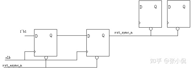
My understanding is that single bit data can reduce the probability of metastable state by shooting, when RST_ async_ When the N signal is valid, the output of the second trigger is low level, and the reset is valid if RST_ async_ When the N signal is released just at the rising edge of clk, the output of the first trigger may be metastable. The probability of metastability can be reduced by taking a beat (the problem of metastability will be summarized in detail later)
Question 3: why does the input of the trigger directly give 1'b1 instead of a reset signal?
A: This is also to save resources and reduce an inverter.
always@(posedge clk or negedge rst_async_n)
    if(~rst_n)begin
        rst_n_d1 <= 1'b0;
        rst_n_d2 <= 1'b0;
    end
    else begin
        rst_n_d1 <= 1'b1;
        rst_n_d2 <= rst_n_d1;
    end
assign rst_sync_n=rst_n_d2;
5, Sequence signal generator
module sequence_gen(
    input clk,
    input rst_n,

    output reg dout
);
localparam [4:0] s0=5'b00001,
                 s1=5'b00010,
                 s2=5'b00100,
                 s3=5'b01000,
                 s4=5'b10000;
reg [4:0] state,next_state;

always@(posedge clk or negedge rst_n)
    if(~rst_n)
        state<=s0;
    else
        state<=next_state;

always@(*)
    case(state)
        s0:next_state=s1;
        s1:next_state=s2;
        s2:next_state=s3;
        s3:next_state=s4;
        s4:next_state=s0;
        default:next_state=s0;
    endcase

always@(posedge clk or negedge rst_n)
    if(~rst_n)
        dout<=1'b0;
    else
        case(next_state)
            s0:dout=1'b0;
            s1:dout=1'b0;
            s2:dout=1'b1;
            s3:dout=1'b0;
            s4:dout=1'b1;
        endcase


endmodule
Simulation code
`timescale 1ns/1ns
module tb_sequence();
parameter PERIOD=10;
bit clk;
reg rst_n;
wire dout;

always #(PERIOD/2) clk=~clk;

initial begin
    rst_n=0;
    #PERIOD;
    rst_n=1;
end

sequence_gen u_sequence_gen(
    .clk   (clk   ),
    .rst_n (rst_n ),
    .dout  (dout  )
);
endmodule
Waveform
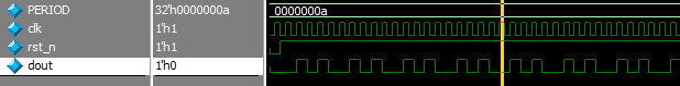
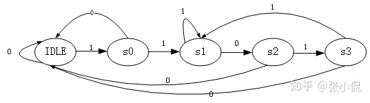
6, Sequence generator
Output 1 when there is "1101" sequence input, otherwise output 0
Draw state machine first
module seqdetection(
    input clk,
    input rst_n,
    input data_i,

    output flag
);
localparam IDLE=5'b00001,
           s0=5'b00010,
           s1=5'b00100,
           s2=5'b01000,
           s3=5'b10000;
reg [4:0] state,next_state;

always@(posedge clk or negedge rst_n)
    if(~rst_n)
        state<=IDLE;
    else
        state<=next_state;

always@(*)
    case(state)
        IDLE:if(data_i)
                next_state=s0;
            else
                next_state=IDLE;
        s0:if(data_i)
                next_state=s1;
            else
                next_state=IDLE;
        s1:if(data_i)
                next_state=s1;
            else
                next_state=s2;
        s2:if(data_i)
                next_state=s3;
            else
                next_state=IDLE;
        s3:if(data_i)
                next_state=s1;
            else
                next_state=IDLE;
    endcase

assign flag=(state==s3)?1'b1:1'b0;
endmodule
Simulation code
`timescale 1ns/1ps
module tb_seqdetection ();

parameter PERIOD=10;
bit clk;
reg rst_n;
reg data_i;
wire flag;

always #(PERIOD/2) clk=~clk;

initial begin
    rst_n=0;
    #PERIOD;
    rst_n = 1;
    repeat(2) seq_gen();
    data_i=1;
    #PERIOD;
    data_i=0;
    #PERIOD;
    data_i=0;
    seq_gen();
end

task seq_gen;
begin
    data_i=1;
    #PERIOD;
    data_i=1;
    #PERIOD;
    data_i=0;
    #PERIOD;
    data_i=1;
    #PERIOD;
end
endtask

seqdetection u_seqdetection(
    .clk    (clk    ),
    .rst_n  (rst_n  ),
    .data_i (data_i ),
    .flag   (flag   )
);

endmodule
Waveform
