Recently, I was talking about a project with a company that mainly works on oil field related equipment, such as tanker trucks, pressure trucks, pump trucks, etc.
I have the impression that as long as there are oil-related businesses, they feel close to money,.
Their boss was impressed when he saw our company's three-dimensional products.Surprisingly, our oilfield management should also be able to build such a three-dimensional system.
Three-dimensional visualization projects for the oil field industry, we have not done any related industries before, but we still have a lot of experience in three-dimensional visualization, such as data centers, hospitals, schools and other three-dimensional visualization projects, including three-dimensional visualization of the direction of smart parks, smart cities, smart towns.
Here are a few 3D visualizations:
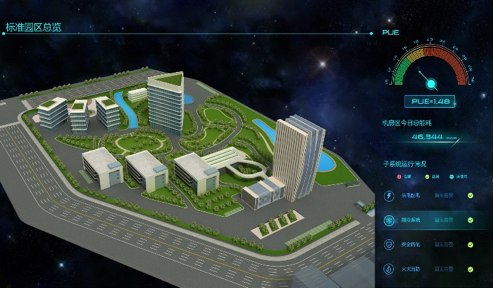
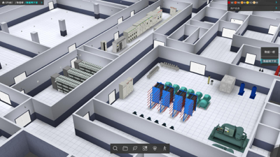
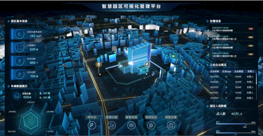
Although we have not done 3D visualization of oil fields directly, it is not too difficult to do with the technical accumulation of the above three-dimensional schemes.
In fact, the customer's requirement is not to build a scene for three-dimensional visualization of an oil field scene.Instead, a three-dimensional oil field layout tool is needed, which allows you to freely set up different oil field scenarios.
This is much more difficult than building a three-dimensional scene directly.
It's hard not to start everything.Everything in the world is hard and easy, and you're done.
After business people and customers establish the contract and formally set up the project, our design sister and development brother are in charge of their respective duties. Let's talk about the general content of the project below.
Build Model Library
The first step is to model. The design group uses 3D modeling tools 3d max or c4d to model the oil field equipment.After modeling, export files in either obj or gltf formats, which are the best file formats supported by our three-dimensional rendering engine.
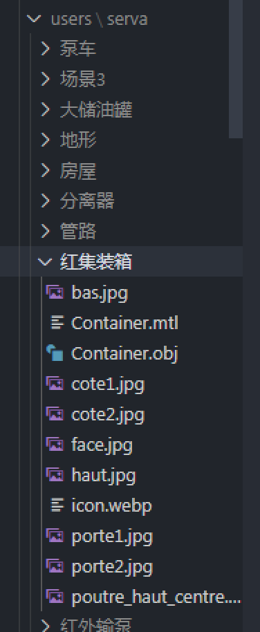
All the modeled model files will eventually be placed in the back-end model library, whose management directory is as follows:
Load Model
Loading models can be loaded using the engine model's load function, such as an obj model load, with the following sample code:
new mono.OBJMTLLoader().load( 'yaliche.obj', 'yaliche.mtl', '',  (node)=> {
    node.type = 'obj';
    box.addByDescendant(node);
  },
);
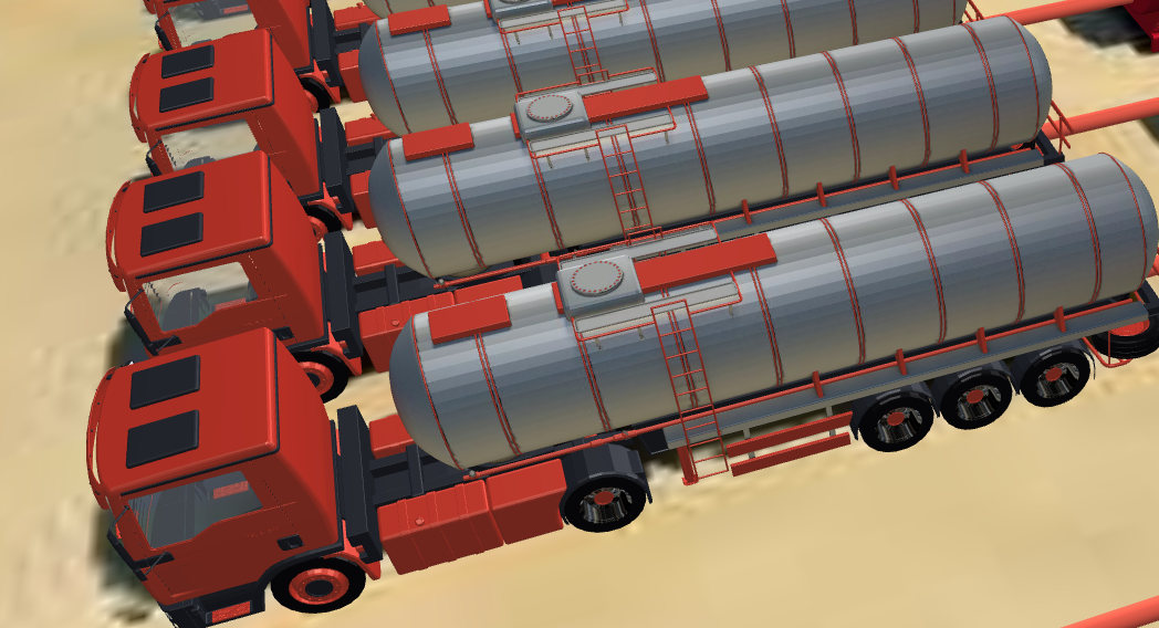
Loading a model of a pressure car is an asynchronous process, so there will be a callback function. After loading, in the callback function, add the three-dimensional object generated by the model file into the scene container box, and after adding, our three-dimensional object will be displayed in the scene, as shown in the following image:
Build Editor Framework
After discussing with the design and development teams, the framework and views of our editor were initially designed to look like the following:
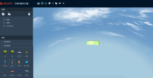
In the upper left corner of the view is our logo, and above it is the toolbar.The left side is divided into scene area and component area, which is a list of creating three-dimensional scenes. The component area is mainly a list of models, and there are also some echarts chart components.
The middle part is the three-dimensional scene rendering area.
For this page layout, I don't think I need to do too much technical elaboration, basically a little bit of front-end developers can achieve similar results.
<div class="layui-layout layui-layout-admin">
      <div class="layui-side layui-bg-black" id="leftTreeWrap">
        <div class="layui-side-scroll">
          <div class="layui-collapse" id="leftTree">
            <div class="sceneTreeWrap">
              <div class="groupTitle">
                scene
              </div>

            </div>
            <div class="groupTitle">
              assembly
            </div>

            <div id="modelGroupWrap">
              <!-- <div class="layui-colla-item modelGroup not-select" id="groundWrap">
                <h2 class="layui-colla-title"><span>Scene Model</span></h2>
                <div class="layui-colla-content" id="groundTree">
                  <div class="tree-wrap"></div>
                </div>
              </div> -->
            </div>
          </div>
        </div>
      </div>
      <div class="layui-body">
        <div class="toolbar">
          <div class="temporaryTool"></div>
        </div>
        <div class="app" tabindex="0">
          <canvas id="monoCanvas"></canvas>
        </div>
      </div>
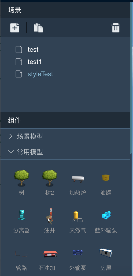
The left sidebar has two sections, a list of scenes and a list of models.The scene list is a tree component, and the model list is an accordion component, as shown in the following figure:
The process of creating a list of models is like this, first getting all the models from the back end:
 getComponentTree({ params: { owner: user } }, 'Synchronization Cloud Component Tree Failed').then((res) => {
      if (res) {
        const treeData = res.data.data;
        treeData.forEach(({ data }) => {
          this.appendModelBtn(data, true);
        });
        // this.renderTreeDom(res.data.data);
      }
    });
Create button s for the model from each model, and the function is appendModelBtn, as follows:
 appendModelBtn(modelData, isNew) {
    const domWrap = this.groupDom[modelData.group];
    if (!domWrap) {
      console.log('Missing group for this type', modelData.group);
      if (modelData.category === 'skyBox') {
        modelData.isNew = true;
        skyData.push({ modelData });
      }
    } else {
      domWrap.querySelector('.tree-wrap').appendChild(this.createModelBtnDom(modelData, isNew));
    }
  }
It is important to note that each model button requires drag and drop functionality.On the model button, you need to listen for drag or dragstart events, which are encapsulated in a separate class Dragger.js, where dragstart events are handled specifically:
 addDragger(parent, subClass, option) {
    parent.addEventListener('dragstart', (e) => {
      let target = null;
      //  Get all the bubbling elements
      const path = eventPath(e);
      for (let i = 0; i < path.length; i += 1) {
        if (path[i].classList && path[i].classList.contains(subClass)) {
          target = path[i];
          break;
        }
      }
...
}
The middle area is the three-dimensional rendering area.First, create a Network3D object, which is an encapsulated three-dimensional rendering page. The bottom layer of the Network3D object is composed of canvas and is rendered in three dimensions using webgl technology.Here is the code to create Network3D:
 const network = new mono.Network3D(box, null, 'monoCanvas');
    network.mode = 'editor';
    window.network = network; // todo
    this.network = network;
    network.bindApp(this);
    network.setRenderSelectFunction(() => false);
    make.Default.path = './static/myModellib/';

    network.setClearColor(0, 0, 0);
    network.setClearAlpha(0);
Once the object is created, make the network size adaptive to the size of the middle area:
 mono.Utils.autoAdjustNetworkBounds(
      network,
      document.querySelector('.app'),
      'clientWidth',
      'clientHeight',
    );
The box object on the network is used to manage the three-dimensional object model to be loaded.As mentioned earlier, drag events have been added to the model list, and models on the model list can be added to the network objects by dragging and dropping, so corresponding events need to be added to the network to add objects:
 onup: (e) => {
        if (!this.sceneTree.senceId && !window.debug) {
          layui.layer.msg('Please create or select a scene first', {
            time: 2000,
          });
          return;
        }
        //  Do not create the mouse when it is not in the canvas
        if (isPosInCanvas(network, e)) {
          network.createElement({
            e,
            configString,
            senceId: this.sceneTree.senceId,
          });
        }
      },
When a model is dragged from the list of models on the left to a network object, a model instance is created after the mouse mouseup event:
 network.createElement({
            e,
            configString,
            senceId: this.sceneTree.senceId,
          });
So far, the entire model list has been loaded and the model drags and drops to create model instances.An example of an oil field that was ultimately dragged is as follows:
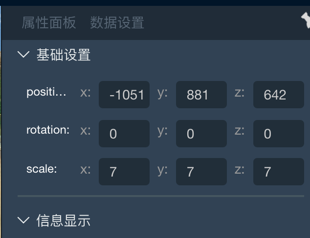
In a 3d scene, you need to adjust the position, rotation angle, and scale of the three-dimensional model, which can be adjusted through the Properties panel:
You can also adjust the model directly in a three-dimensional scene by using the three-dimensional editing function. To use the adjust editing function, simply add the following line of code:
 const editInteraction = new mono.EditInteraction(network);
    editInteraction.setScaleable(false);
    editInteraction.setRotateable(false);
    editInteraction.setTranslateable(true);
    editInteraction.setDefaultMode('');

    network.setInteractions([...network.getInteractions(), editInteraction]);
The EditInteraction class is used to adjust the position, rotation angle, and scale of the model.The keyboard allows you to adjust which property EditInteraction is currently adjusting:
case 82: // r When element ation is selected, the toggle action is to rotate
          if (this.network.getIsMonoElement(this.network.currComponent)) {
            const editInteraction = this.network.getInteractions()[2];
            editInteraction.setScaleable(false);
            editInteraction.setRotateable(true);
            editInteraction.setTranslateable(false);
          }
          break;
        case 84: // t When element ation is selected, the toggle action is move
          if (this.network.getIsMonoElement(this.network.currComponent)) {
            const editInteraction = this.network.getInteractions()[2];
            editInteraction.setScaleable(false);
            editInteraction.setRotateable(false);
            editInteraction.setTranslateable(true);
          }
          break;
        case 89: // y Switches to zoom when element ation is selected
          if (this.network.getIsMonoElement(this.network.currComponent)) {
            const editInteraction = this.network.getInteractions()[2];
            editInteraction.setScaleable(true);
            editInteraction.setRotateable(false);
            editInteraction.setTranslateable(false);
          }
          break;
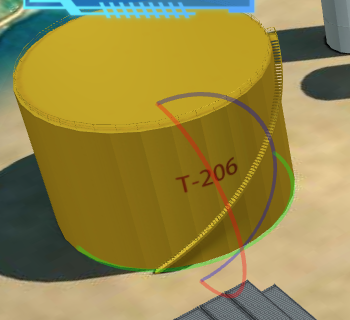
r key to switch to rotation angle adjustment:
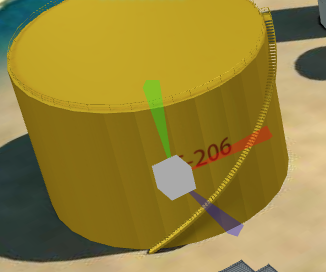
Adjustment of the t-key switch to position:

y key toggles to zoom adjustment:
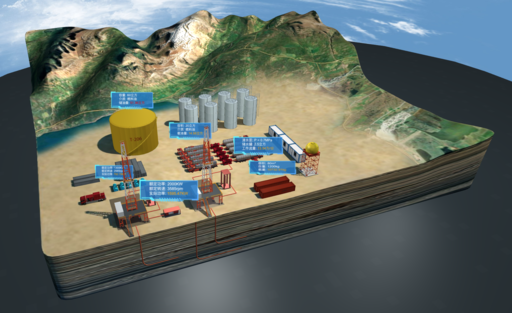
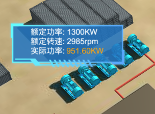
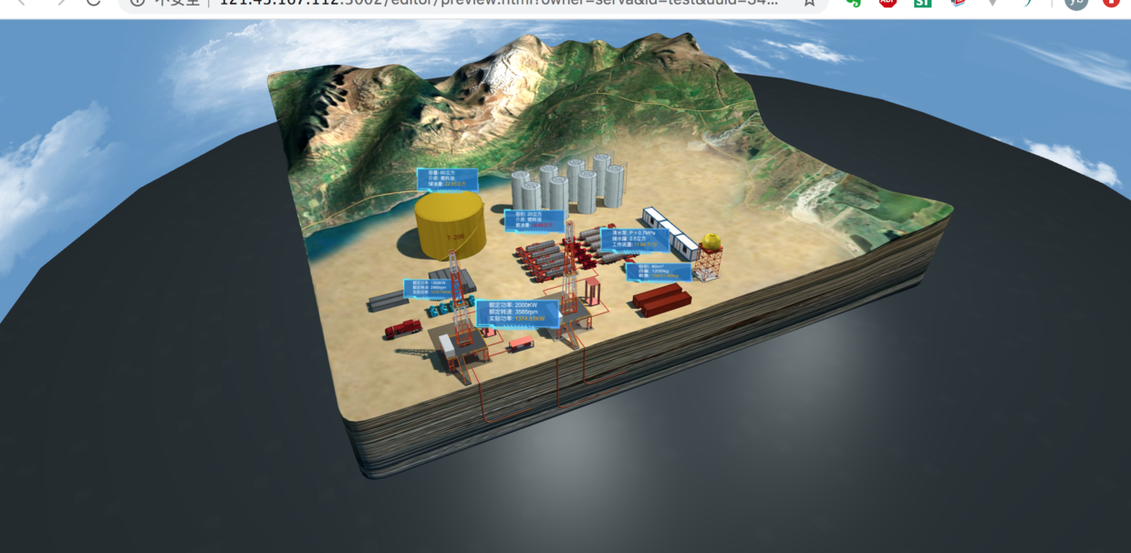
After dragging and dropping to create a scene, each object can also be docked with real-time data, which will produce the following effects:
Once you have finished creating the scene and docking the data, you can publish the scene. Click the Preview button on the toolbar to publish and preview the scene.The last final released result map is as follows:
Interested in getting the editor, please email:
terry.tan@servasoft.com
Welcome to the public number "Uncle ITman Biao".Biao Shu, with more than 10 years of development experience, is currently the system architect, technical director, technical trainer, and professional planner of the company.In-depth research in computer graphics, WebGL, front-end visualization.I have a strong interest in training and training programmers'thinking ability and programmer career planning.