VLAN
LAN ------- LAN
MAN -- MAN
WAN -- wide area network
LAN in VLAN refers to LAN, which represents a broadcast domain.
VLAN ----------- virtual LAN: switches and routers work together to logically divide the original broadcast domain into multiple virtual broadcast domains.
Judge whether it is in the same broadcast domain: whether it is in the same flood range, Ping once.
VLAN configuration
1. Create VLAN
<Huawei>display vlan------see VLAN
IEEE------802.1Q
VID------12 Bit binary composition (0)-4095)0 And 4095 reserved (1-4094)

[Huawei]vlan 2   ----establish VLAN
[Huawei]vlan 3
[Huawei]vlan batch 2 to 10  -----Batch creation VLAN
[Huawei]undo vlan  batch 4 to 10  ----- Batch delete VLAN
2. Divide the interface into corresponding VLAN s
VID configuration is mapped to the interface of the switch to realize VLAN division - Physical VLAN or Layer-1 VLAN
VID configuration is mapped to the MAC address in the data frame to realize VLAN division - layer 2 VLAN

The type field in the data frame marks the protocol used by the upper layer. We can map the protocol type and VID configuration - layer 3 VLAN
Forwarding principle after adding VLAN to the switch: the data comes to the switch through the interface. The switch first looks at the source MAC address in the data frame, records its mapping relationship with the interface in the MAC address table, and records the VID corresponding to the interface in the MAC address table. Then look at the target Mac. If the target MAC is recorded in the MAC address table and the corresponding VID is the same as that of the interface corresponding to the source MAC, unicast is performed; Otherwise, flooding will be carried out. Except for the incoming interface, all interfaces with the same VID as the incoming interface------- Logically, a broadcast domain is divided into multiple virtual broadcast domains.
To mark a data frame, you need to add a new field. The TAG length is 4 bytes ----- TAG. It contains 12 bit VID information.
We call the frame carrying tag 802.1Q, tagged frame. Frames that do not include tags are called untagged frames.
We call the link between the switch and the computer ACCESS link. The ACCESS link can only pass through untagged frames, and all frames belong to the same VLAN; The link between the switch and the switch is called trunk link. Trunk trunk allows 802.1Q frames, and these frames can belong to multiple VLANs.
[Huawei]int g 0/0/1  -----Access interface
[Huawei-GigabitEthernet0/0/1]port link-type access  -----Select link type
[Huawei-GigabitEthernet0/0/1]port default  vlan 2   ----Define allowed VLAN

[Huawei]port-group group-member g 0/0/3 to  g 0/0/4---Create Interface Group

[Huawei-port-group]port link-type access
[Huawei-GigabitEthernet0/0/3]port link-type access
[Huawei-GigabitEthernet0/0/4]port link-type access

[Huawei-port-group]port default vlan 3
[Huawei-GigabitEthernet0/0/3]port default vlan 3
[Huawei-GigabitEthernet0/0/4]port default vlan 3
3. Configure trunk road (SW-sw) (SW-R)
[Huawei]int g 0/0/5
[Huawei-GigabitEthernet0/0/5]port link-type trunk
[Huawei-GigabitEthernet0/0/5]port trunk allow-pass vlan 2 to 3
[Huawei-GigabitEthernet0/0/1]port trunk allow-pass vlan all  ----Allow all VLAN
4. Inter VLAN routing (single arm routing)
Sub interface: a physical interface
Three kinds of virtual interfaces (sub interface, loopback interface and null interface)
[r1]interface GigabitEthernet 0/0/0.1     -----Create sub interface
[r1-GigabitEthernet0/0/0.1]ip address 192.168.1.1 24
[r1]interface GigabitEthernet 0/0/0.2     ------Create sub interface
[r1-GigabitEthernet0/0/0.2]ip address 192.168.2.1 24

[r1]interface GigabitEthernet 0/0/0.2
[r1-GigabitEthernet0/0/0.2]dot1q termination vid 3------Definition of sub interface management VLAN
[r1-GigabitEthernet0/0/0.2]arp broadcast  enable--------open ARP radio broadcast
A strategy
ACL ---- access control linked list
Role of ACL:
1. Access control: match the traffic on the interface where the router traffic flows in or out, and then perform corresponding actions.
(permit ------- allow, deny ------- reject).
2. Capturing streams of interest: ACLS need to be combined with other services. ACLS are responsible for matching traffic according to corresponding rules, while other services perform corresponding actions on the matched traffic. For example: flow control: Qos ---- quality of service technology.
ACL matching rule: match one by one from top to bottom. After matching, execute according to the corresponding action, and do not match downward.
If the device is Cisco's system: there will be a rule to reject all at the end of the access list.
If the equipment is Huawei's system, a rule allowing all users will be implied at the end of the access list.
ACL classification:
Basic ACL: only focus on the source Ip of the packet.
Advanced ACL: focus not only on the source ip, but also on the target ip, protocol and port number.
Layer 2 ACL: MAC and source MAC
User defined ACL:
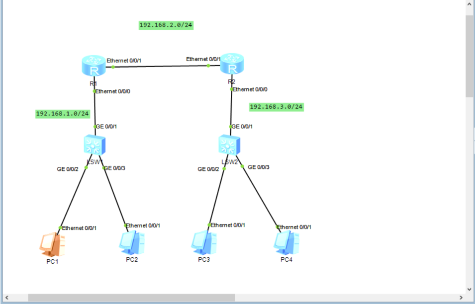
Requirement 1: PC1 can access the 3.0 network segment, but PC2 cannot

Location rule of basic ACL: since the basic ACL only focuses on the source ip address of the packet, it should be as close to the target as possible when configuring the call to avoid accidental access to other places.
1.establish ACL
[r2]acl 2000
[r2-acl-basic-2000]
INTEGER<2000-2999>    Basic access-list (add to current using rules)---basic ACL
INTEGER<3000-3999>    Advanced access-list(add to current using rules)---senior ACL
INTEGER<4000-4999>    MAC address access-list(add to current using rules)---Second floor ACL
INTEGER<10000-10999>  Apply MPLS ACL---User defined ACL
2.Add rule
[r2-acl-basic-2000]rule deny source 192.168.1.3 0.0.0.0
 Difference between wildcard and unmask: 0 and 1 in wildcard can be interspersed: 0.255.0.255
[r2-acl-basic-2000]display acl 2000
Basic ACL 2000, 2 rules
ACL's step is 5
rule 5 deny (0 times matched)
rule 10 deny source 192.168.1.3 0 (0 times matched)
Huawei ACL The number of rules starts from 5 by default and is automatically added in steps of 5
[r2-acl-basic-2000]rule 6 deny source 192.168.1.2 0.0.0.0 ---Add rule by sequence number
[r2-acl-basic-2000]undo rule 6     -----Delete rule by sequence number
3.Call on interface ACL
[r2-GigabitEthernet0/0/0]traffic-filter outbound acl 2000
Only one interface can be called in one direction ACL list
Requirement 2: PC1 can access PC3, but not PC4. PC2 can access the 3.0 network segment

Location rule of advanced ACL: because it pays attention to both source IP and target IP, the location should be as close to the source as possible.
[r1]acl 3000
[r1-acl-adv-3000]rule deny ip source 192.168.1.2 0.0.0.0 destination 192.168.3.3
 0.0.0.0  ---senior ACL Rules of
[r1-Ethernet0/0/0]traffic-filter inbound acl 3000-----call ACL
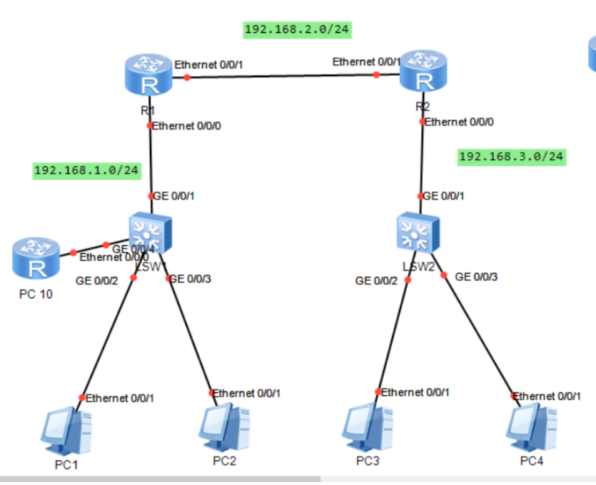
Requirement 3: PC1 can ping R2, but not talknetr2
talnet ---- remote login protocol
Management mode of Router: in band management and out of band management
Out of band management: manage the router through the consle port
Manage router through AUX port
In band management: manage the router through talnet------ 1. It must be accessible between the login device and the logged in device; 2. The logged in device must start the talnet service. (content of the third day)
Manage the router through the web;
Manage the router through SNMP;
Talnet ---- C / s ---- communication is based on TCP 23 communication
Start the talnet service:
[r2]aaa     ------get into aaa Service (a place to store and manage accounts)
[r2-aaa]
[r2-aaa]local-user longlong privilege  level 15 password cipher 123456
Info: Add a new user.            ----Create a user
[r2-aaa]local-user longlong service-type telnet ----Define user type
[r2]user-interface  vty  0 4       -----Turn on 0 at the same time--4 5 Login ports
[r2-ui-vty0-4]authentication-mode  aaa   -----Set authentication mode


[r1-acl-adv-3001]rule deny tcp source 192.168.1.10 0.0.0.0 destination 192.168.2
.2 0.0.0.0 destination-port eq 23

[r1-Ethernet0/0/0]traffic-filter inbound acl 3001
NAT -- network address translation
In our IP address space, A, B and C IP addresses take out part of the IP addresses as private IP addresses (private IP addresses), and the rest are called public IP addresses (common IP addresses).
Class A: 10.0.0.0 – 10.255.255.255 (255.0.0.0) (1 class a address)
Class B: 172.16.0.0-172.31.255.255 (16 segment class B address)
Class C: 192.168.0.0-192.168.255.255 (256 segment class C address)

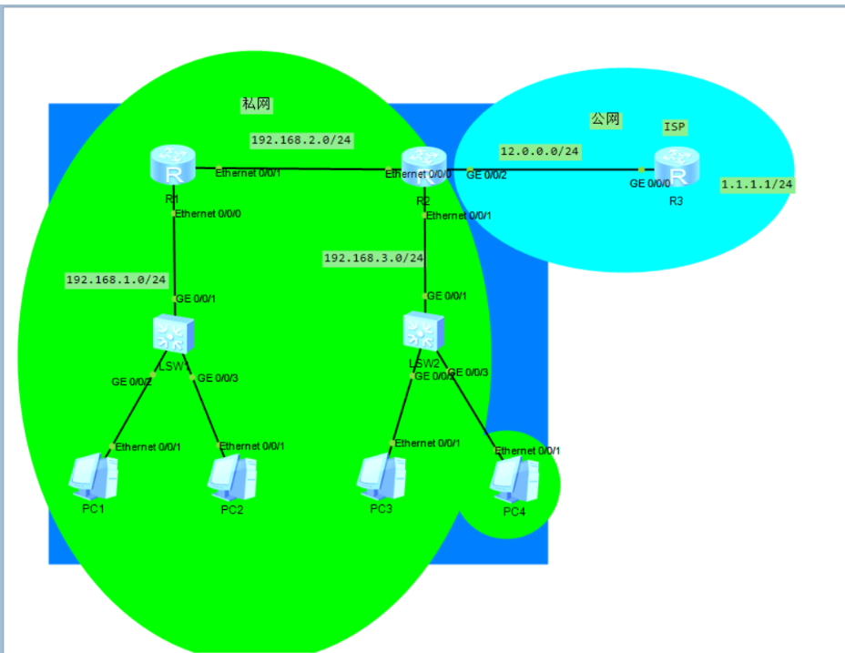
Private IP addresses are reusable. Private IP address cannot be used in the Internet. We habitually call the network using private IP address private network. The public IP address can be used for communication in the Internet. The network using the public IP address for communication is called the public network.
NAT ---- network address translation technology. Its basic function is to realize the conversion of private network IP address and public network address.
In Huawei equipment, all NAT related configurations are configured on the outgoing interface of the boundary router.
Static NAT
Through configuration, a static address mapping table is maintained on our private network boundary router. The static address mapping table reflects the one-to-one correspondence between public IP and private IP.
Dynamic NAT
NAPA
Port mapping
Static NAT
Through configuration, a static address mapping table is maintained on our private network boundary router. The static address mapping table reflects the one-to-one correspondence between public IP and private IP.
[Huawei-GigabitEthernet0/0/2]nat static global 12.0.0.3 inside 192.168.1.2
12.0.0.3---Floating address
[r2-GigabitEthernet0/0/2]display nat static  ----View static address mapping table
Dynamic NAT ---- many to many
1. Create a public IP group
[r2]nat address-group 1 12.0.0.4 12.0.0.8
2.acl grabs streams of interest
[r2-acl-basic-2000]rule permit source 192.168.0.0 0.0.255.255
3. Bind dynamic IP and ACL
[r2-GigabitEthernet0/0/2]nat outbound 2000 address-group 1 no-pat
The biggest problem of dynamic NAT is whether it is a one-to-one relationship at the same time.
NPAT ----------------- pat ------- network address port translation
One to many NAPT ------- easy IP
2.acl grabs streams of interest
[r2-acl-basic-2001]rule permit source 192.168.0.0 0.0.255.255
3. Configure the output interface
[r2-GigabitEthernet0/0/2]nat outbound 2001
Many to many NAT
1. Create a public IP group
[r2]nat address-group 1 12.0.0.4 12.0.0.8
2.acl grabs streams of interest
[r2]acl 2001
[r2-acl-basic-2001]rule permit source 192.168.0.0 0.0.255.255
3. Bind public IP and ACL
[r2-GigabitEthernet0/0/2]nat outbound 2001 address-group 1
Port mapping:
Bind the port corresponding to the public IP with the port of our service. As long as you access the corresponding port of the public IP, wrap the data to the corresponding port of our server.