Daily share:
Any restriction starts from your heart.
1, Concept and advantages of VLAN
1. Split broadcast domain
1) Physical segmentation: divide the network into several small networks physically, and then connect different networks with routing equipment that can isolate broadcasting to realize communication.
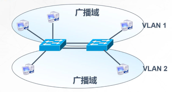
2) Logical segmentation: logically divide the network into several small virtual networks, namely VLAN. VLAN works in the data link layer of OSI reference model. A VLAN is a switching network, in which all users are in a broadcast domain, and each VLAN realizes communication through the connection of routing equipment.
2. VLAN overview and advantages
1) Control broadcast: each VLAN is an independent broadcast domain, which reduces the occupation of broadcast on network broadband and improves network transmission efficiency. In addition, broadcast storm in one VLAN will not affect other VLANs.
2) Enhance network security: data can only be exchanged between ports in the same VLAN, and ports in different VLANs cannot be accessed directly. Therefore, by dividing VLANs, individual hosts can be restricted from accessing servers and other resources to improve network security.
3) Simplify network management: data can only be exchanged between ports in the same VLAN, and ports in different VLANs cannot be accessed directly. Therefore, by dividing VLANs, individual hosts can be restricted from accessing servers and other resources to improve network security.
2, Type of VLAN
1. Static routing
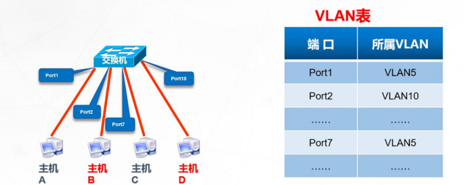
Port based VLAN
2. Dynamic routing
Dynamic VLAN division based on MAC address
3, Configuration of static VLAN
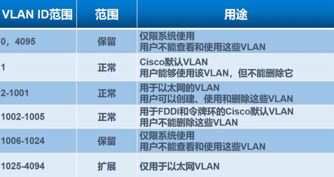
1. VLAN range
(Cisco switches support up to 4096 VLAN s)
There are two ways to divide VLAN s:
1) Divide VLANs one by one: vlan 10
vlan 20
2) Batch Division: vlan bat 10 20
2. To configure a static VLAN
1) Create VLAN
2) Add the port of the switch to the corresponding VLAN
3) Verify VLAN configuration
3. Huawei matching method
[Huawei]int g0/0/0
[Huawei gigabitethernet 0 / 0 / 0] port link type access (p l a) (interface mode)
[Huawei gigabitethernet 0 / 0 / 0] port default VLAN 10 (p d v 10) (interface mode)
[Huawei-GigabitEthernet0/0/0] undo shutdown
4, Trunk introduction and configuration
Trunk is to realize cross exchange and interworking with VLAN through a physical link.
1. The role of Trunk
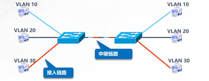
Link type in switching network:
Access link: only single label traffic is allowed to pass through
Relay link: allow multi tag traffic to pass through
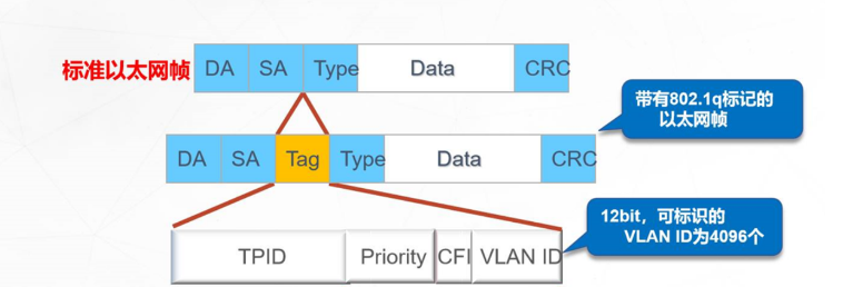
2. Package type
There are two types of encapsulation to implement relay over Ethernet
● ISL (Cisco private standard)
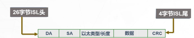
●IEEE 802.1q
3. Trunk matching
[Huawei]int g0/0/0
[Huawei gigabitethernet 0 / 0 / 0] port link type trunk (p l t) (interface mode)
[Huawei gigabitethernet 0 / 0 / 0] port trunk allow pass VLAN all (p t a v a) (interface mode)
[Huawei-GigabitEthernet0/0/0] undo shutdown
5, Forwarding principle of layer 3 switch
1. Three layer switching technology
1) Use the three-layer switching technology to realize the communication between VLAN s;
2) Layer 3 switching = layer 2 switching + layer 3 forwarding
2,MLS
1. Traditional MLS:
1) In the process of layer 3 forwarding, layer 2 should be re encapsulated;
2) On the layer 3 switch, the layer 3 engine processes the first packet of the data stream;
3) The exchange ASIC learns the layer 2 rewriting information from the layer 3 engine and creates an MLS entry in the hardware;
4) Responsible for rewriting and forwarding subsequent packets in the data stream
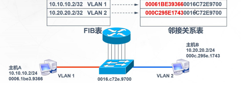
2. MLS based on CEF (latest technology of Cisco)
CEF is a topology based forwarding model:
Forwarding information base (FIB)
Adjacency relation table
6, Configuration of layer 3 switch
1. Configuration instance
(code can be copied directly)
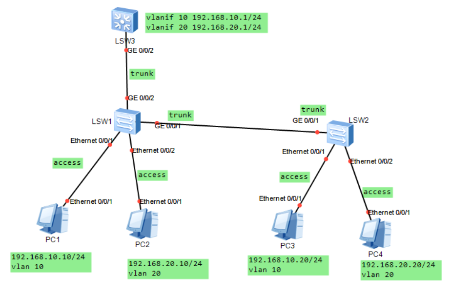
LSW2
The code is as follows (example):
<Huawei>sys
[Huawei]sysname SW2
[SW2]vlan bat 10 20
[SW2]int e0/0/1
[SW2-Ethernet0/0/1]p l a
[SW2-Ethernet0/0/1]p d v 10
[SW2-Ethernet0/0/1]dis this
[SW2-Ethernet0/0/1]un sh
[SW2-Ethernet0/0/1]int e0/0/2
[SW2-Ethernet0/0/2]p l a
[SW2-Ethernet0/0/2]p d v 20
[SW2-Ethernet0/0/2]dis this
[SW2-Ethernet0/0/2]un sh
[SW2-Ethernet0/0/2]int g0/0/1
[SW2-GigabitEthernet0/0/1]p l t
[SW2-GigabitEthernet0/0/1]p t a v a
[SW2-GigabitEthernet0/0/1]dis this
[SW2-GigabitEthernet0/0/1]un sh
[SW2-GigabitEthernet0/0/1]int g0/0/2
[SW2-GigabitEthernet0/0/2]p l t
[SW2-GigabitEthernet0/0/2]p t a v a
[SW2-GigabitEthernet0/0/2]dis this
[SW2-GigabitEthernet0/0/2]un sh
LSW3
The code is as follows (example):
<Huawei>sys
[Huawei]sysname SW3
[SW3]vlan 10 20
[SW3]int e0/0/1
[SW3-Ethernet0/0/1]p l a
[SW3-Ethernet0/0/1]p d v 10
[SW3-Ethernet0/0/1]dis this
[SW3-Ethernet0/0/1]un sh
[SW3-Ethernet0/0/1]int e0/0/2
[SW3-Ethernet0/0/2]p l a
[SW3-Ethernet0/0/2]p d v 20
[SW3-Ethernet0/0/2]dis this
[SW3-Ethernet0/0/2]un sh
[SW3-Ethernet0/0/2]int g0/0/1
[SW3-GigabitEthernet0/0/1]p l t
[SW3-GigabitEthernet0/0/1]p t a v a
[SW3-GigabitEthernet0/0/1]dis this
[SW3-GigabitEthernet0/0/1]un sh
LSW1
The code is as follows (example):
<Huawei>sys
[Huawei]sysname SW1
[SW1]vlan bat 10 20
[SW1]int g0/0/2
[SW1-GigabitEthernet0/0/2]p l t
[SW1-GigabitEthernet0/0/2]p t a v a
[SW1-GigabitEthernet0/0/2]dis ths
[SW1-GigabitEthernet0/0/2]un sh
[SW1-GigabitEthernet0/0/2]int vlanif 10
[SW1-Vlanif10]ip add 192.168.10.1 24
[SW1-Vlanif10]dis this
[SW1-Vlanif10]un sh
[SW1-Vlanif10]int vlanif 20
[SW1-Vlanif20]ip add 192.168.20.1 24
[SW1-Vlanif20]dis this
[SW1-Vlanif20]un sn
PC1 ping PC2
PC>ping 192.168.20.10