Previously, we successively explained the introduction of software and hardware and counting examples, the basic use of camera, visual positioning based on shape matching, whether BLOB has detection, measuring size, the calibration function used in machine vision scheme, and the function of ZDevelop software to identify bar code and QR code.
In this course, we share with you the basic measurement function of machine vision - measuring point / line / circle.
Video tutorial: VPLC series machine vision motion control all-in-one machine quick start 8 measuring point line circle (2)
01 detection principle
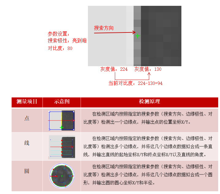
The function of measuring point / line / circle used in machine vision is a vision algorithm based on edge detection.
Edge detection is to search the transition edge points that meet the requirements of polarity change and contrast pixel by pixel in a certain search area according to the specified direction.
02 measuring point / line / circle features
1. Simple implementation
The algorithm of measuring point / line / circle is based on edge detection, which is easy to implement.
2. Position following is required
The measuring device itself does not have positioning function. If the position of the detected product is not fixed, the corresponding position of the measuring device cannot be determined. At this time, it is necessary to rely on positioning functions such as matching for position tracking.
01 measuring point application scenario
1. Precise positioning
Detecting the position of feature edge points and outputting corresponding coordinates can achieve accurate positioning, which is often used in conjunction with matching (rough positioning).
2. Fitting straight line
A straight line can be fitted by detecting two feature edge points, and the straight line data can be output for further detection.
02 measuring line application scenario
1. Precise positioning
It is usually used to detect the intersection position coordinates of two straight lines as the positioning position. The output position accuracy is higher than that of matching output. It is often used in conjunction with matching (rough positioning).
2. Test straightness
The straightness can be judged according to the number of abnormal edges not on the straight line after fitting the straight line.
3. Measure dimensions
The edge dimension distance of the product can be obtained by detecting two straight lines and calculating the distance between the two straight lines.
03 application scenario of measuring circle
1. Measuring circle
Measure the circular features and obtain the center and radius of the circle.
2. Positioning
Through measuring the characteristics of the circle, the coordinate data of the center position is output for accurate positioning, which is often used in conjunction with matching (rough positioning).
3. Nine point calibration
The calibration coefficient can be calculated by detecting the image coordinate data of nine circle centers on the solid circle matrix calibration plate and the world coordinate data corresponding to the calibration plate.
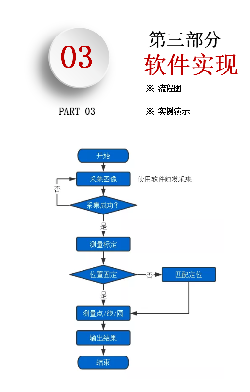
Flow chart of measuring point / line / circle
01 example demonstration
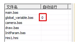
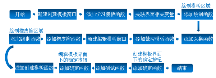
1. Open ZDevelop software: new project → new HMI file → new main Bas file, used to write interface response function → new global_variable.bas file is used to store global variables → create initparam Bas file is used to initialize measurement parameters → new camera Bas file is used to realize camera acquisition function → new draw Bas file is used to update the drawing graphic refresh interface → add the file to the project.
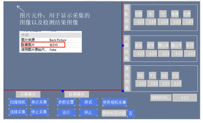
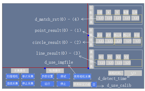
2. Design the operation interface. The operation interface only carries out image acquisition operation and detection execution operation, and displays the data results.
3. In global_ variable. The bas file is added to the global variable used.
 '''''Most global variables use array structures'''''

  ''Note: basic Many functions in programming will TABLE(Data structure of system)As a parameter

  ''here table Are used as intermediate variables

  ''table 0-20 As an intermediate variable used in matching

  ''table 50-70 As roi Use of intermediate variables during drawing


  ''table 21-22,Represents the coordinate system of the mouse button control

  ''table 31-35,Represents the corresponding image coordinates after control coordinate conversion

  ''table 111-114,Represents the locator area roi Parameter, belonging to the control coordinate system

  ''table 121-124,Indicates the eraser area roi Parameter, belonging to the control coordinate system

  ''table 81-98,Represents the image coordinates of the nine points used for calibration

  ''table 131-148,Represents the world coordinates of the nine points used for calibration

  '***********Define program task related variables**********************


  'Main task status

  '0 - uninitialized

  '1 - stop it

  '2 - In operation

  '3 - Stopping

  GLOBAL DIM main_task_state

  main_task_state = 1


  'Calibration

  global is_ca_success


  'Operation task switch

  GLOBAL DIM run_switch

  run_switch = 0


  'Acquisition task switch

  '0 - Stop collection

  '1 - Request collection

  GLOBAL DIM grab_switch

  grab_switch = 0


  'Location detection main task id - 10

  GLOBAL DIM main_task_id

  main_task_id = 10


  'Camera continuous acquisition thread id - 7

  GLOBAL DIM grab_task_id

  grab_task_id = 7


  '***********End defining program task related variables******************


  '***********Define camera acquisition related variables**********************


  'Camera type,"",Use Haikang camera here-"mvision"

  GLOBAL DIM CAMERA_TYPE(100)

  'CAMERA_TYPE = "mindvision;basler;mvision;huaray;basler;zmotion"

  CAMERA_TYPE = "mvision"


  'Number of cameras

  GLOBAL cam_num

  cam_num = 0


  'Camera mode,-1 Continuous acquisition, 0-Trigger acquisition

  GLOBAL cam_mode

  cam_mode = 0


  '***********End defining camera acquisition related variables******************


  'Define return to main interface flag,1-Returned, 0-Not returned

  GLOBAL DIM d_is_rtn_loc

  d_is_rtn_loc = 1


  '***********Define template related variables*************************


  'Define create template flag bit,1-Created template, 0-No template created

  GLOBAL DIM d_is_creModel

  d_is_creModel = 0


  'Learning template parameters,starAngle,endAngle,minScale,maxScale,thresh,numlevel,reduce,angleStep,scaleStep

  GLOBAL DIM d_mod_param(9)


  '***********End defining template related variables**********************


  '***********Define and edit template related variables*********************


  'Define edit template flags,0-Indicates that the template is not edited, 1-Represents an edit template

  GLOBAL DIM d_edit_m

  d_edit_m = 0


  'Defines the use of eraser function flags,0-Indicates the area to be erased, 1-Indicates the erase area

  GLOBAL DIM d_isMask_m

  d_isMask_m = 1


  'Defines the of the eraser roi Parameter, followed by the image coordinates of the upper left corner and the lower right corner of the rectangle x,y,x,y

  GLOBAL DIM d_locator_roi(4),d_eraser_roi(4)


  'Define square eraser size width

  GLOBAL DIM d_eraser_size

  d_eraser_size = 5


  'Defines the rectangular area of the eraser on the interface control

  GLOBAL DIM c_rect(4)


  'Define mouse status flags,0-Indicates that the mouse is released, 1-Indicates that the mouse is pressed

  GLOBAL DIM d_mouse_s

  d_mouse_s = 0


  '***********End defining and editing template related variables******************


  '***********Define match detection related variables*********************


  'Match detection parameters,minScore,matchNum,minDist,thresh,accuracy,speed,polor

  GLOBAL DIM d_match_param(7)


  'To define a learning template roi Parameters and eraser roi Parameter, followed by the image coordinates of the upper left corner and the lower right corner of the rectangle x,y,x,y

  GLOBAL DIM d_locator_roi(4),d_eraser_roi(4)


  'Matching results, score,x,y,angle,scale, At present, only the first target is saved for multi-target matching

  GLOBAL DIM d_match_rst(5)


  '***********End definition match detection related variables******************


  'Define variables that cache intermediate pictures and result pictures during program execution

  GLOBAL ZVOBJECT grabImg

  GLOBAL ZVOBJECT subImg,copy_subImg,colorSubImg, s_mod

  GLOBAL ZVOBJECT modRe


  '***********Define coordinate calibration related variables*********************

  'Define whether to use the calibration function flag, 0-Do not use the calibration function, 1-Using the calibration function

  GLOBAL DIM d_use_calib

  d_use_calib = 0


  'Define calibration success flag, 0-Calibration failed, 1-Calibration successful

  GLOBAL DIM d_calib_success

  d_calib_success = 0


  'Calibration parameters

  GLOBAL ZVOBJECT ca_param


  'Calibration parameter array, in order: calibration type, contrast, polarity, minimum area, maximum area and world coordinate point spacing

  GLOBAL DIM d_ca_param(6) 'd The beginning represents the data structure


  'Calibration error, minimum error, maximum error, average error

  GLOBAL DIM ca_min_err,ca_max_err,ca_avg_err

  ca_min_err = 0

  ca_max_err = 0

  ca_avg_err = 0


  'Common color variables

  GLOBAL C_RED, C_GREEN, C_BLUE, C_YELLOW

  C_RED = RGB(255, 0, 0)

  C_GREEN = RGB( 0,255, 0)

  C_BLUE = RGB( 0, 0,255)

  C_YELLOW= RGB(255,255, 0)


  'Calibration matrix

  GLOBAL ZVOBJECT ca_mat

  '***********End defining coordinate calibration related variables******************


  '***********Define measurement points/Line/Circle dependent variable******************

  'Define test consumption time

  GLOBAL DIM d_detect_time


  'Define whether to use correction source,0-Do not use correction source, 1-Use correction source

  GLOBAL DIM d_use_locator

  '

  'Whether to draw the gauge

  GLOBAL DIM line_status,circle_status,point_status

  line_status=0

  circle_status=0

  point_status=0


  'Measuring point/Line/Circle parameter settings, including edge polarity/Edge position/contrast ratio/Filter size/Number of scans/Scan width

  GLOBAL DIM d_point_param(4),d_line_param(6), d_circle_parm(6)


  'Draw result parameters

  GLOBAL DIM draw_point(2),draw_line(4),draw_circle(3)

  '***********End defining measurement points/Line/Circle dependent variable**************

  'Define point measurer area/Line gauge area/Circle gauge area

  GLOBAL DIM d_roi_rect1(5),d_roi_rect2(5),d_roi_arc(6)


  'Set the base coordinates for creating the template

  GLOBAL DIM d_match_base_rst(5)


  GLOBAL ZVOBJECT mat_rigid,latch '


  '**********************Point line circle measurement data results*****************

  GLOBAL DIM point_result(5),line_result(5),circle_result(5)


  '***********Define variables related to the function of reading local files**************

  ''Note that this function is only valid when using the emulator

  'Defines whether to use local picture flags

  GLOBAL DIM d_use_imgfile


  'Define local picture index

  GLOBAL DIM d_index


  'Define the path to read pictures

  GLOBAL DIM File_Name(100)


  '***********End defining variables related to the function of reading local files**********

  RUN "Hmi1.hmi",1
4. In initparam Initialize the measurement variables in the bas file.
end


    GLOBAL SUB init_meas_param() 'Initialization parameters


      'Initialize locator roi parameter

      d_locator_roi(0) = 240 'top left corner x

      d_locator_roi(1) = 180 'top left corner y

      d_locator_roi(2) = 400 'Lower right corner x

      d_locator_roi(3) = 300 'Lower right corner y


      'Initialize template parameters

      d_mod_param(0) = -180 'Starting angle

      d_mod_param(1) = 180 'Termination angle

      d_mod_param(2) = 1 'Minimum zoom

      d_mod_param(3) = 1 'Maximum zoom

      d_mod_param(4) = 80 'threshold

      d_mod_param(5) = 0 'Default pyramid layers

      d_mod_param(6) = 0 'Default reduced feature point

      d_mod_param(7) = 0 'Default angle step

      d_mod_param(8) = 0 'Default zoom step


      'Initialize matching measurement parameters

      d_match_param(0) = 50 'Minimum score

      d_match_param(1) = 1 'Number of matches

      d_match_param(2) = 0 'Default minimum spacing

      d_match_param(3) = 40 'Minimum threshold

      d_match_param(4) = 0 'accuracy

      d_match_param(5) = 9 'speed

      d_match_param(6) = 0 'Polarity


      'Initialize matching location results

      d_match_rst(0) = 0 'fraction

      d_match_rst(1) = 0 'position X

      d_match_rst(2) = 0 'position Y

      d_match_rst(3) = 0 'angle

      d_match_rst(4) = 0 'proportion


      'Initialization of measurement parameters of points

      d_point_param(0)=0

      d_point_param(1)=0

      d_point_param(2)=30

      d_point_param(3)=5


      'Line measurement parameter initialization

      d_line_param(0)=0

      d_line_param(1)=0

      d_line_param(2)=30

      d_line_param(3)=5

      d_line_param(4)=10

      d_line_param(5)=8


      'Initialization of measurement parameters of circle

      d_circle_parm(0)=0

      d_circle_parm(1)=0

      d_circle_parm(2)=20

      d_circle_parm(3)=5

      d_circle_parm(4)=10

      d_circle_parm(5)=8


      'Initialize variables related to coordinate calibration

      d_ca_param(0) = 0 'Calibration type

      d_ca_param(1) = 120 'contrast ratio

      d_ca_param(2) = 0 'Polarity

      d_ca_param(3) = 80 'Minimum area

      d_ca_param(4) = 20000 'Maximum area

      d_ca_param(5) = 9 'World coordinate point spacing

      ca_min_err = 0 'Minimum error

      ca_max_err = 0 'maximum error

      ca_avg_err = 0 'average error


      d_detect_time = 0

      d_use_locator = 0 'Correction source is not used by default

      d_use_imgfile = 1

      d_index = 0


      TABLE(31,100,100,60,40,60,8,5) 'Point measurer initialization

      TABLE(231,100,100,60,40,60,8,5) 'Line meter initialization

      TABLE(551,100,100,60,50,0,360,8,5) 'Circle meter initialization

  END SUB
5. Associate relevant variables in the operation interface.
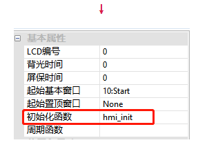
6. In main Add the running interface initialization function in the bas file and associate the HMI interface initialization function name.
 'Run the interface initialization function, power on and execute it once

  GLOBAL SUB hmi_init()


  grab_switch = 0 'Initialize the acquisition task switch without starting the acquisition task

  main_task_state = 1 'The main task status of initialization positioning detection is stop status 1

  ZV_SETSYSINT("LineWidth",5) 'Set the paint brush width to 5 pixels

  ZV_RESETCLIPSIZE(1280, 1024) 'During initialization, the clipping size of the region is set according to the image resolution, where the image resolution is 1280 x1024

  ZV_LATCHSETSIZE(0, HMI_CONTROLSIZEX(10, 1), HMI_CONTROLSIZEY(10, 1)) 'Sets the size of the latch

  init_meas_param() 'Initialize measurement parameters


  ZV_IMGGENCONST(subImg,40,30,1,0,0) 'Initialize template sub image


  'Define matching intermediate result variables

  ZVOBJECT contlist1, tsContlist1, mat_rigid1

  ZVOBJECT contlist2, tsContlist2, mat_rigid2


  ZV_READIMAGE(grabImg,"\8\calib.bmp",1) 'read...\flash\8 Under directory calib.bmp Gray image, which is used for coordinate calibration when loading local image simulation

  ZV_LATCHCLEAR(0) 'Clear latch channel 0

  ZV_LATCH(grabImg,0) 'Displayed in latch channel 0


  END SUB
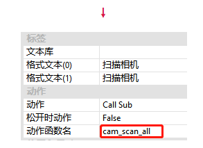
7. In camera Add the function function of collection related buttons in BAS file and associate the action function name.
    end

  'The function that responds when the scan camera button is pressed on the main interface

  GLOBAL SUB cam_scan_all()


  if(d_use_imgfile=1)then

      ?"Please press the use local picture button to turn off this function"

  return

  endif


  ZV_SETSYSINT("LogLevel", 7) 'Set controller information

  ZV_SETSYSSTR("DataDir","")


  CAM_SCAN(CAMERA_TYPE) 'Scanning camera, CAMERA_TYPE="mvision"

  cam_num = CAM_COUNT() 'Gets the number of cameras scanned

  if (0 = cam_num) then 'If the number of cameras=0,Print prompt information

      ? "Camera not found"


      return 'Exit the sub function without executing further

  endif

  ?"cam_num = " cam_num 'If a camera is scanned, print the number of cameras

      cam_mode = 0 'Set soft trigger acquisition


  CAM_SEL(0) 'Select the first camera scanned to operate

  CAM_SETEXPOSURE(5000) 'Set the camera exposure time to 5000 us

  CAM_SETMODE(cam_mode) 'Set software trigger mode

  CAM_START(0) 'Turn on the camera


  END SUB


  'The function executed by pressing the single acquisition button on the main interface

  GLOBAL SUB btn_grab()


  ''If d_use_imgfile=1 The function of reading local pictures is only effective when using the simulator. Please comment out this part of the code when using the controller

  if (d_use_imgfile=1) then

  if(d_index=3) then

      d_index=0

  endif

  File_Name="\8\"+TOSTR(d_index,1,0)+".bmp" '.../flash/3/The path name of the picture in the directory

  ZV_IMGREAD(grabImg,File_Name,0)

  ZV_LATCH(grabImg, 0)

  d_index=d_index+1

  return

  endif

  ''End of reading local picture function


  if cam_num = 0 then

      ?"Please scan the camera first!"

  return

  endif


  CAM_SETPARAM("TriggerSoftware", 0) 'Send trigger instruction

  CAM_GET(grabImg, 0) 'Get a frame of image and store it in grabImg Variable

  ZV_LATCH(grabImg, 0) 'Displays the image in latch channel 0


  END SUB


  'The main interface is the function to respond by pressing the continuous acquisition button

  GLOBAL SUB btn_cgrab()

  if grab_switch =1 then 'If it is already in the continuous execution state, print the prompt message and exit the function

      ?"It is running continuously. Please do not repeat the operation!"

  return

  endif


  if( d_use_imgfile =0) then


  if cam_num = 0 then 'If the number of cameras=0,Print a prompt and exit the function

          ?"Please scan the camera first!"

  return

  endif

  endif


  grab_switch = 1 'Set the acquisition task switch to 1

  if (1 = grab_switch) then

      if (0 = PROC_STATUS(grab_task_id)) then

          RUNTASK grab_task_id, grab_task 'Start continuous acquisition task

      endif

  endif


  END SUB


  'Acquisition task implementation function

  grab_task:

  while(1)

  if (0 = grab_switch) then 'If the acquisition task switch=0 That is, when the stop acquisition button is pressed

      exit while 'Exit loop

  endif


  'Repeat the following

  btn_grab()

  wend

  END


  'Response function of pressing the stop acquisition button on the main interface

  GLOBAL SUB btn_stopCgrab()

  if grab_switch =0 then 'If the collection is stopped, print the prompt and exit the function

      ?"Continuous acquisition is not enabled!"

  return

  endif


      grab_switch = 0 'Set the acquisition task switch to 0

  END SUB
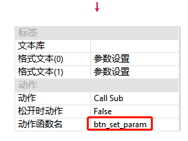
8. Create a new operation interface, press the [parameter setting] button to pop up the parameter setting window, and design the interface layout.
9. Add the function that responds when the [parameter setting] button is pressed in the operation interface, and associate the action function name.
  'Response function when the parameter setting button is pressed on the operation interface

  GLOBAL SUB btn_set_param()


      ZV_LATCHSETSIZE(0, HMI_CONTROLSIZEX(11, 1), HMI_CONTROLSIZEY(11, 1)) 'Sets the size of the latch

      ZV_LATCHCLEAR(0)

      ZV_LATCH(grabImg,0) 'Displayed in latch channel 0 as the background picture of the display area

      HMI_SHOWWINDOW(11)


  END SUB
10. Refer to Chapter III "visual positioning based on shape matching" to add shape matching function. The adding process is as follows:
  end


  'And draw(That is, select ROI)The relevant interface refresh drawing functions are placed in this bas In the document


  DIM is_redraw 'Drawing flag, 0 means no drawing, 1 means drawing

  is_redraw = 0


  DIM sr_mpos_x, sr_mpos_y, hit_pos


  'The response function when the learning template button is pressed on the main interface

  GLOBAL SUB btn_sel_loc()

      ZV_LATCHSETSIZE(0, HMI_CONTROLSIZEX(12, 60), HMI_CONTROLSIZEY(12, 60)) 'Sets the latch size of the create template window latch channel 0

      ZV_LATCHSETSIZE(1, HMI_CONTROLSIZEX(12, 38), HMI_CONTROLSIZEY(12, 38)) 'Sets the latch size of latch channel 1 of the create template window

      SET_COLOR(RGB(0,255,0)) 'appoint draw The color used by the command


      ZV_LATCHCLEAR(0) 'Clear latch channel 0

      ZV_LATCH(grabImg, 0) 'Display the acquired image and display it in latch channel 0

      ZV_LATCH(colorSubImg, 1) 'The display template image is displayed in latch channel 1


      'image roi Coordinate conversion control roi

      is_redraw = 0

      d_is_rtn_loc = 0

      TABLE(111, d_locator_roi(0), d_locator_roi(1),d_locator_roi(2),d_locator_roi(3))

      ZV_POSFROMIMG(0, 2, 111, 111) 'Convert image coordinates to HMI Control coordinates

      HMI_SHOWWINDOW(12)


  END SUB


  'Update the area of the locator according to the mouse operation, that is, the effective area of the learning template

  GLOBAL SUB update_locator()


      if mouse_scan(21) = 1 then 'Scan mouse down operation

          is_set_roi_m_down = 1

          sr_mpos_x = table(21)

          sr_mpos_y = table(22)

          hit_pos = ZV_HMIADJRECT(sr_mpos_x, sr_mpos_y, 111, -1) 'The hit position can be changed only when pressed

          is_redraw = 1

          endif

          if mouse_scan(21) = -1 then 'Scan mouse release operation

          is_set_roi_m_down = 0

          sr_mpos_x = table(21)

          sr_mpos_y = table(22)

          ZV_HMIADJRECT(sr_mpos_x, sr_mpos_y, 111, hit_pos)

          is_redraw = 1

          endif

      if (is_set_roi_m_down and MOUSE_state(21)) then

          sr_mpos_x = table(21)

          sr_mpos_y = table(22)

          ZV_HMIADJRECT(sr_mpos_x, sr_mpos_y, 111, hit_pos)

          is_redraw = 1

      endif


      if (1 = is_redraw) then

          'control roi Coordinate to image roi coordinate

          is_redraw = 0

          ZV_POSTOIMG(0, 2, 111, 50) 'TABLE(50)Used temporarily as an intermediate variable

          d_locator_roi(0) = TABLE(50)

          d_locator_roi(1) = TABLE(51)

          d_locator_roi(2) = TABLE(52)

          d_locator_roi(3) = TABLE(53)

          SET_REDRAW

      endif


  END SUB


  'Draws a locator based on the updated mouse position coordinates roi

  GLOBAL SUB draw_locator()

      DRAWRECT(TABLE(111), TABLE(112), TABLE(113), TABLE(114))


      local cx,cy

      cx = (TABLE(111) + TABLE(113)) / 2

      cy = (TABLE(112) + TABLE(114)) / 2


      DRAWLINE(cx-5, cy, cx+5, cy) 'Center cross

      DRAWLINE(cx, cy-5, cx, cy+5)


  END SUB


  'The function to respond after pressing the intercept template button in the create template interface

  GLOBAL SUB btn_getSubImg()

      LOCAL mod_w,mod_h

      ZV_IMGGETSUB(grabImg, subImg, d_locator_roi(0), d_locator_roi(1), d_locator_roi(2)-d_locator_roi(0)+1, d_locator_roi(3)-d_locator_roi(1)+1)


      ZV_IMGINFO(subImg,0)

      mod_w = TABLE(0)

      mod_h = TABLE(1)


      ZV_REGENRECT(modRe,0,0,mod_w, mod_h)

      ZV_LATCHCLEAR(1)

      ZV_LATCH(subImg, 1)


  END SUB


  'The function that responds when the eraser button is pressed in the create template interface

  GLOBAL SUB btn_sel_erase()

      ZV_LATCHSETSIZE(1, HMI_CONTROLSIZEX(13, 1), HMI_CONTROLSIZEY(13, 1)) 'Sets the size of the latch

      ZV_LATCHSETSIZE(2, HMI_CONTROLSIZEX(13, 15), HMI_CONTROLSIZEY(13, 15)) 'Sets the size of the latch

      SET_COLOR(RGB(0,255,0)) 'Sets the color used by the brush when drawing

      ZV_LATCHCLEAR(1) 'Clear latch

      ZV_IMGCOPY(subImg, copy_subImg) 'Copy template sub image to copy_subImg In image variable

      ZV_REGION(copy_subImg, modRe, 1, 0) 'Draw on template image modRe The non effective area of the image, drawn in black, used for masking

      ZV_LATCH(copy_subImg, 1) 'Show copied template diagram


      HMI_SHOWWINDOW(13) 'Open the edit template window


  end sub


  'Update eraser according to mouse operation/Location of the recovery area

  GLOBAL SUB update_eraser()

      DIM c_size_eraser 'The size of the eraser on the control

      DIM eraser_pos_x,eraser_pos_y

      d_mouse_s = MOUSE_STATE(21) 'When the mouse is pressed

      eraser_pos_x = TABLE(21)

      eraser_pos_y = TABLE(22)


      c_size_eraser = ZV_LENFROMIMG(0, d_eraser_size) 'Converts the image size of the eraser to the control size

      c_rect(0, eraser_pos_x - c_size_eraser, eraser_pos_y - c_size_eraser, eraser_pos_x + c_size_eraser, eraser_pos_y + c_size_eraser)

      'Draw to(eraser_pos_x,eraser_pos_y)Center, 2*c_size_eraser Square eraser area with side length


      DIM hmi_w,hmi_h

      if (eraser_pos_x >= c_size_eraser) and (eraser_pos_y >= c_size_eraser) and (eraser_pos_x <= HMI_CONTROLSIZEX(12, 1) - c_size_eraser)and (eraser_pos_y <= HMI_CONTROLSIZEy(12, 1) - c_size_eraser) THEN

          SET_REDRAW(0,0, HMI_CONTROLSIZEX(12, 1), HMI_CONTROLSIZEY(12, 1))'Redraws the latch channel 0 area on the edit template window

      endif


      if d_mouse_s = 1 and d_edit_m = 1 then 'If the mouse is pressed and the template flag is edited=1 Time

          btn_pro_eraser() 'Execute processing eraser function

      endif


  END SUB


  'Handle eraser function

  global sub btn_pro_eraser()

      ZVOBJECT tmp_re

      TABLE(121, c_rect(0), c_rect(1))

      ZV_POSTOIMG(1, 1, 121, 121)

      ZV_REGENRECT(tmp_re, TABLE(121), TABLE(122), 2 * d_eraser_size + 1, 2 * d_eraser_size + 1)


      if (d_isMask_m = 1) then 'shield

          ZV_REDIFF(modRe, tmp_re, modRe) 'calculation modRe and tmp_re And save it to modRe in

      else 'recovery

             ZV_REUNION(modRe, tmp_re, modRe) 'calculation modRe and tmp_re Union and save to modRe in

      endif


      ZV_IMGCOPY(subImg, copy_subImg) 'Copy template sub image to copy_subImg In image variable

      ZV_REGION(copy_subImg, modRe, 1, 0) 'Draw on template image modRe The non effective area of the image, drawn in black, used for masking

      ZV_LATCH(copy_subImg, 1) 'Show copied template diagram

  end sub


  'Update paint eraser area

  GLOBAL SUB draw_eraser()

      if d_edit_m = 0 then 'If you edit a template flag

          return 'Return sub function, do not continue to execute

      endif


      DRAWRECT(c_rect(0), c_rect(1), c_rect(2), c_rect(3))'Draw eraser area

  END SUB


  'The function that responds when the create template button is pressed in the edit template interface

  GLOBAL SUB btn_loc_creModel()

      d_is_creModel = 1

      'Create template

      ZV_SHAPECREATERE(subImg, modRe,s_mod, d_mod_param(0), d_mod_param(1), d_mod_param(2), d_mod_param(3), d_mod_param(4), d_mod_param(5), d_mod_param(6), d_mod_param(7), d_mod_param(8))


      ZV_SHAPECONTOURS(s_mod, contlist1, 0) 'Get the template outline on the pyramid of level 0

      ZV_GRAYTORGB(subImg, colorSubImg) 'Gray image conversion to RGB chart

      ZV_IMGINFO(colorSubImg, 0) 'obtain colorSubImg Image information and store it in table0 in

      ZV_GETRIGIDVECTOR(mat_rigid1, 0, 0, 0, TABLE(0)/2, TABLE(1)/2, 0)'Calculating rigid transformation matrix

      ZV_CONTAFFINE(contlist1, mat_rigid1, tsContlist1) 'Affine transformation of contour or contour sequence

      ZV_CONTLIST(colorSubImg, tsContlist1, ZV_COLOR(0, 255, 0), 0) 'stay colorSubImg Draw a green contour sequence on the image


      ZV_LATCHCLEAR(2)

      ZV_LATCH(colorSubImg, 2)


      btn_loc_test()

      d_match_base_rst(0) = d_match_rst(0)

      d_match_base_rst(1) = d_match_rst(1)

      d_match_base_rst(2) = d_match_rst(2)

      d_match_base_rst(3) = d_match_rst(3)

      d_match_base_rst(4) = d_match_rst(4)

  END SUB


  'The function executed when the OK button is pressed in the edit template interface

  GLOBAL SUB btn_erase_cfm()

      ZV_LATCHCLEAR(0)

      ZV_LATCH(grabImg, 0) 'Display image on latch

      HMI_CLOSEWINDOW(13) 'Close the edit template window

  END SUB


  'The function that responds when the test button is pressed in the create template interface

  GLOBAL SUB btn_loc_test()

      if (d_is_creModel = 0) then

              ?"No template created!"

          return

      endif


  'Start matching


  ZVOBJECT match_rst, sImg, colorImg

  ZV_GAUSSBLUR(grabImg, sImg, 3)

  ZV_SHAPEFIND(s_mod, sImg, match_rst, d_match_param(0), d_match_param(1), d_match_param(2), d_match_param(3), d_match_param(4), d_match_param(5), d_match_param(6))


  ZV_MATINFO(match_rst, 0)

  ZV_GRAYTORGB(sImg, colorImg)


  if TABLE(0) > 0 then

          local rowr

          for rowr = 0 to TABLE(0)-1

              ZV_MATGETROW(match_rst, rowr, 5, 3) 'obtain match_rst The second in the matrix rowr Row data to table in,table Maximum length 5

              if(rowr = 0) then

              if(is_ca_success = 1 AND d_use_calib=1) then

                  ZV_CALTRANSW(ca_param, TABLE(4),TABLE(5),8) 'Pixel coordinates to world coordinates

                  d_match_rst(0) = TABLE(3)

                  d_match_rst(1) = TABLE(8)

                  d_match_rst(2) = TABLE(9)

                  d_match_rst(3) = TABLE(6)

                  d_match_rst(4) = TABLE(7)

                  ZV_GETRIGIDVECTOR(mat_rigid1, 0, 0, 0, TABLE(4), TABLE(5), TABLE(6))'Calculating rigid transformation matrix

                  ZV_CONTAFFINE(contlist1, mat_rigid1, tsContlist1)'Affine transformation of contour or contour sequence

                  ZV_CONTLIST(colorImg, tsContlist1, ZV_COLOR(0, 255, 0), 0)'stay colorSubImg Draw a green contour sequence on the image

                  else

                  d_match_rst(0) = TABLE(3)

                  d_match_rst(1) = TABLE(4)

                  d_match_rst(2) = TABLE(5)

                  d_match_rst(3) = TABLE(6)

                  d_match_rst(4) = TABLE(7)

                  ZV_GETRIGIDVECTOR(mat_rigid1, 0, 0, 0, TABLE(4), TABLE(5), TABLE(6))'Calculating rigid transformation matrix

                  ZV_CONTAFFINE(contlist1, mat_rigid1, tsContlist1)'Affine transformation of contour or contour sequence

                  ZV_CONTLIST(colorImg, tsContlist1, ZV_COLOR(0, 255, 0), 0)'stay colorSubImg Draw a green contour sequence on the image

                  endif

                  endif

                  next

                  else

                  d_match_rst(0) = -1

                  d_match_rst(1) = -1

                  d_match_rst(2) = -1

                  d_match_rst(3) = -1

                  d_match_rst(4) = -1

              endif

                  ZV_LATCH(colorImg, 0)

              END SUB

              'The function that responds when the OK button is pressed in the create template interface

              GLOBAL SUB btn_loc_cfm()

              grab_switch = 0 'Turn off continuous acquisition of correction source

              d_is_rtn_loc = 1

              ZV_LATCHSETSIZE(0, HMI_CONTROLSIZEX(11, 1), HMI_CONTROLSIZEY(11, 1)) 'Sets the size of the latch

              ZV_LATCHCLEAR(0)

              ZV_LATCH(grabImg, 0) 'Display image on latch

              ZV_LATCH(grabImg, 1) 'Display image on latch

              HMI_CLOSEWINDOW(12)

  END SUB
11. Refer to Chapter 6 "calibration" and add the coordinate calibration function. The adding process is as follows:
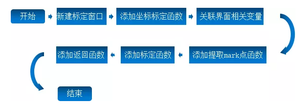
'Response function when the coordinate calibration button is pressed in the parameter setting interface
GLOBAL SUB btn_calib()
ZV_LATCHSETSIZE(0, HMI_CONTROLSIZEX(14, 91), HMI_CONTROLSIZEY(14, 91)) 'Sets the latch size of the coordinate calibration window latch channel 0
ZV_LATCHCLEAR(0) 'Clear latch channel 0
ZV_LATCH(grabImg, 0) 'Display the acquired image and display it in latch channel 0
HMI_SHOWWINDOW(14)
END SUB
'Press extract on the coordinate calibration interface mark Function that responds when a button is clicked
GLOBAL SUB btn_ca_extract()
ZVOBJECT inppts, ppts, wpts
'Extract pixel coordinates
ZV_CALGETSCAPTS(grabImg, inppts, d_ca_param(1), d_ca_param(2), d_ca_param(3), d_ca_param(4))
ZV_MATINFO (inppts, 400)
DIM row,col
row = TABLE(400)
col = TABLE(401)
if(row * col = 18) then
TABLE(150) = 1 'extract mark Point success
else
TABLE(150) = 0 'extract mark Point failure
return
endif
'according to mrak Calculate world coordinates by point spacing and pixel coordinates
ZV_CALGETPTSMAP(inppts,ppts,wpts,d_ca_param(5))
ZV_MATINFO (ppts, 400)
row = TABLE(400)
col = TABLE(401)
if(row * col = 18) then
TABLE(150) = 1 'extract mark Point success
else
TABLE(150) = 0 'extract mark Point failure
return
endif
'Pixel coordinates and world coordinates table in
DIM i
FOR i=0 TO row-1
ZV_MATGETROW (ppts, i, col, 81 + i*col)
ZV_MATGETROW (wpts, i, col, 131 + i*col)
NEXT
'Settings for drawing mark Point image
ZVOBJECT color
ZV_GRAYTORGB(grabImg, color)
'And draw mark Dot the cross
DIM j, pixNum 'Number of pixels
pixNum = 0
FOR i=0 TO 2
FOR j=0 TO 2
ZV_MARKER(color, TABLE(81 + 2 * pixNum), TABLE(81 + 2 * pixNum + 1), 0, 40, C_GREEN)
pixNum = pixNum + 1
NEXT
NEXT
'Draw with text mark Sequence number of points
FOR i=0 TO 8
ZV_TEXT (color, TOSTR(i,1,0), TABLE(81+2*i)-20, TABLE(81+2*i +1)-40, 20, C_BLUE)
NEXT
ZV_LATCH(color, 0)
END SUB
'Coordinate calibration interface is a function of response when the calibration button is pressed
GLOBAL SUB btn_ca_calib()
ZV_IMGINFO(grabImg,0)
ZV_CALCAM(ppts,wpts,ca_param,TABLE(0),TABLE(1),d_ca_param(0))
is_ca_success=1
'Calculate calibration error
ZV_CALERROR(ca_param, ppts, wpts, 0)
ca_min_err = TABLE(1)
ca_max_err = TABLE(2)
ca_avg_err = TABLE(0)
END SUB
'The function that responds when the return button is pressed on the coordinate calibration interface
GLOBAL SUB btn_ca_param_rtn()
HMI_CLOSEWINDOW(14)
END SUB
12.In the parameter setting interface, the [collect image] button is associated with the action function name btn_grab.
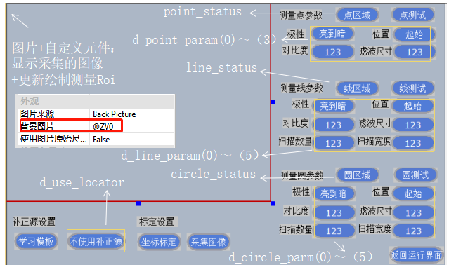
13.stay draw.bas Add points to file/Line/Update the drawing function of the circle gauge area and associate the refresh function and drawing function in the custom component properties window.
'Refresh function of point, line and circle measurer
GLOBAL SUB update_roi ()
if point_status = 1 then
SET_REDRAW 'Draw the first click
if (mouse_scan(21) = 1 ) then 'Scan press operation
hit_pos = ZV_HMIADJRECT2(table(21), table(22), 31, -1) 'The hit position can be changed only when pressed
is_redraw = 1
endif
if (mouse_scan(21) = -1 ) then 'Scan release operation
ZV_HMIADJRECT2(table(21), table(22), 31, hit_pos)
is_redraw = 1
endif
if (MOUSE_state(21)) then
ZV_HMIADJRECT2(table(21), table(22), 31, hit_pos)
is_redraw = 1
endif
if (1 = is_redraw) then
is_redraw = 0
ZV_POSTOIMG(0, 1, 31, 41)
d_roi_rect1(0) = TABLE(41)
d_roi_rect1(1) = TABLE(42)
d_roi_rect1(2) = ZV_LENTOIMG(0, TABLE(33))
d_roi_rect1(3) = ZV_LENTOIMG(0, TABLE(34))
d_roi_rect1(4) = TABLE(35)
SET_REDRAW
endif
elseif line_status=1 then
SET_REDRAW 'Draw the first click
if (mouse_scan(21) = 1)then 'Scan press operation
hit_pos = ZV_HMIADJRECT2(table(21), table(22),231, -1) 'The hit position can be changed only when pressed
is_redraw = 1
endif
if (mouse_scan(21) = -1) then 'Scan release operation
ZV_HMIADJRECT2(table(21), table(22), 231, hit_pos)
is_redraw = 1
endif
if (MOUSE_state(21)) then
ZV_HMIADJRECT2(table(21), table(22), 231, hit_pos)
is_redraw = 1
endif
if (1 = is_redraw) then
is_redraw = 0
ZV_POSTOIMG(0, 1, 231, 41)
d_roi_rect2(0) = TABLE(41)
d_roi_rect2(1) = TABLE(42)
d_roi_rect2(2) = ZV_LENTOIMG(0, TABLE(233))
d_roi_rect2(3) = ZV_LENTOIMG(0, TABLE(234))
d_roi_rect2(4) = TABLE(235)
SET_REDRAW
endif
elseif circle_status=1 then
SET_REDRAW
is_redraw = 0
if (mouse_scan(21) = 1 AND TABLE(21)>0 AND TABLE(21)0 AND TABLE(22)
hit_pos = ZV_HMIADJARC(table(21), table(22), 551, -1) 'The hit position can be changed only when pressed
is_redraw = 1
endif
if (mouse_scan(21) = -1 AND TABLE(21)>0 AND TABLE(21)0 AND TABLE(22)
ZV_HMIADJARC(table(21), table(22), 551, hit_pos)
is_redraw = 1
endif
if (MOUSE_state(21)) then
ZV_HMIADJARC(table(21), table(22), 551, hit_pos)
is_redraw = 1
endif
if (1 = is_redraw) then
is_redraw = 0
'Control coordinates to image coordinates
ZV_POSTOIMG(0, 1, 551, 61)
TABLE(63) = ZV_LENTOIMG(0, TABLE(553))
TABLE(64) = ZV_LENTOIMG(0, TABLE(554))
TABLE(65, TABLE(555), TABLE(556))
d_roi_arc(0) = TABLE(61)
d_roi_arc(1) = TABLE(62)
d_roi_arc(2) = TABLE(63)
d_roi_arc(3) = TABLE(64)
d_roi_arc(4) = TABLE(65)
d_roi_arc(5) = TABLE(66)
SET_REDRAW
endif
else
SET_REDRAW
endif
END SUB
'Drawing function of point, line and circle
GLOBAL SUB draw_roi()
if point_status = 1 and line_status=0 and circle_status=0 then
SET_COLOR(C_BLUE)
ZV_HMIRECT2(31, 300)
DRAWLINE(TABLE(300), TABLE(301), TABLE(302), TABLE(303)) 'Outer rectangle
DRAWLINE(TABLE(302), TABLE(303), TABLE(304), TABLE(305))
DRAWLINE(TABLE(304), TABLE(305), TABLE(306), TABLE(307))
DRAWLINE(TABLE(306), TABLE(307), TABLE(300), TABLE(301))
DRAWLINE(TABLE(308), TABLE(309), TABLE(310), TABLE(311)) 'Direction arrow
DRAWLINE(TABLE(312), TABLE(313), TABLE(310), TABLE(311))
DRAWLINE(TABLE(314), TABLE(315), TABLE(310), TABLE(311))
endif
if line_status=1 and point_status=0 and circle_status=0 then
SET_COLOR(C_BLUE)
TABLE(236,d_line_param(4),d_line_param(5)) 'Measuring the number and width of scans
ZV_HMIRECT2(231, 350)
DRAWLINE(TABLE(350), TABLE(351), TABLE(352), TABLE(353)) 'Outer rectangle
DRAWLINE(TABLE(352), TABLE(353), TABLE(354), TABLE(355))
DRAWLINE(TABLE(354), TABLE(355), TABLE(356), TABLE(357))
DRAWLINE(TABLE(356), TABLE(357), TABLE(350), TABLE(351))
DRAWLINE(TABLE(358), TABLE(359), TABLE(360), TABLE(361)) 'Direction arrow
DRAWLINE(TABLE(362), TABLE(363), TABLE(360), TABLE(361))
DRAWLINE(TABLE(364), TABLE(365), TABLE(360), TABLE(361))
if (0 = TABLE(366)) then return
SET_COLOR(C_GREEN)
DIM idx
for idx = 0 to TABLE(366)-1
DRAWLINE(TABLE(367+idx*4), TABLE(368+idx*4), TABLE(369+idx*4), TABLE(370+idx*4))
next
endif
if circle_status=1 and line_status=0 and point_status=0 then
SET_COLOR(C_BLUE)
TABLE(557) = d_circle_parm(4) 'Number of sub regions
TABLE(558) = d_circle_parm(5) 'Sub area width
ZV_HMIARC(551, 400) 'Draw a ring
'Draw an arc
DRAWARC(TABLE(400), TABLE(401), TABLE(402), TABLE(404), TABLE(405)) 'Inner radius
DRAWARC(TABLE(400), TABLE(401), TABLE(403), TABLE(404), TABLE(405)) 'Outer radius
DRAWLINE(TABLE(400), TABLE(401)-5, TABLE(400), TABLE(401)+5)
DRAWLINE(TABLE(400)-5, TABLE(401), TABLE(400)+5, TABLE(401))
'Draw boundary lines
DIM idx
for idx = 0 to TABLE(406)-1
DRAWLINE(TABLE(407+idx*4), TABLE(408+idx*4), TABLE(409+idx*4), TABLE(410+idx*4))
next
SET_COLOR(C_GREEN)
DIM startid
startid = 407+TABLE(406)*4
for idx = 0 to TABLE(startid)-1
DRAWLINE(TABLE(startid+1+idx*4), TABLE(startid+2+idx*4), TABLE(startid+3+idx*4), TABLE(startid+4+idx*4))
next
endif
END SUB
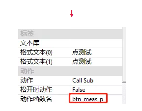
14. In main In the bas file, add the function that responds when the [point test] button is pressed in the parameter setting interface, and associate the action function name.
  'Function of response when point measurement button is pressed on parameter interface

  GLOBAL SUB btn_meas_p()

      Point_measure()

      ZV_GRAYTORGB(grabImg, latch) 'Before drawing graphics, you need to convert the gray image to RGB chart

      ZV_MARKER(latch, draw_point(0), draw_point(1), 0, 20, C_GREEN) 'Draw marker points

      ZV_LATCH(latch,0)'Display image results

  END SUB


  'Implementation sub function of measurement point

  GLOBAL SUB Point_measure()

      ZVOBJECT mr_p, tmp


  if d_use_locator=0 then 'If no correction source is used

          'Generate rectangular gauge

      ZV_MRGENRECT2(mr_p, d_roi_rect1(0), d_roi_rect1(1),d_roi_rect1(2), d_roi_rect1(3),d_roi_rect1(4), 1)

  endif

  'Detection point

      ZV_MRPOS(mr_p, grabImg,tmp,d_point_param(3),d_point_param(2),d_point_param(0),d_point_param(1))

      'Get the data of the corresponding row of the matrix

      ZV_MATGETROW(tmp, 0, 3, 386)

          'Assign a result variable to draw a graph

      draw_point(0)=TABLE(386)

      draw_point(1)=TABLE(387)


      if d_use_calib=1 and is_ca_success=1 then 'If the calibration function is used and the calibration has been successful

          ZV_CALTRANSW(ca_param, TABLE(386),TABLE(387),386) 'Pixel coordinates to world coordinates

      endif

  'The assignment result variable is used to display the data result

  point_result(0)=TABLE(386)

  point_result(1)=TABLE(387)

  END SUB
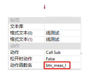
15. In main In the bas file, add the function that responds when the [line test] button is pressed in the parameter setting interface, and associate the action function name.
  Response function when the offline measurement button is pressed in the parameter interface

  GLOBAL SUB btn_meas_l()

          btn_ml_test()

      ZV_GRAYTORGB(grabImg, latch)'Before drawing graphics, you need to convert the gray image to RGB chart

      ZV_LINE(latch,draw_line(0),draw_line(1),draw_line(2),draw_line(3),zv_color(0,255,0)) 'Draw line

      ZV_LATCH(latch,0)'Display image results


  END SUB


  'Realization sub function of measuring straight line

  GLOBAL SUB btn_ml_test()


      ZVOBJECT mr_l, tmp


      if d_use_locator=0 then 'If no correction source is used

              'Generate a linear measurer

          ZV_MRGENLINE(mr_l,d_roi_rect2(0), d_roi_rect2(1),d_roi_rect2(2), d_roi_rect2(3), d_roi_rect2(4), 1,d_line_param(4),d_line_param(5))

      endif

      'Set advanced parameters of the meter area, including filter size, edge threshold, edge polarity and edge position

      ZV_MRSETADV(mr_l, d_line_param(3), d_line_param(2), d_line_param(0),d_line_param(1))

      'Initialize result array

      TABLE(486, 0, 0, 0, 0)

      'Detect the line and assign the result to the array with the starting address of 486

      ZV_MRLINE(mr_l, grabImg, tmp, 486)

      'Assign a result variable to draw a graph

      draw_line(0)=TABLE(486)

      draw_line(1)=TABLE(487)

      draw_line(2)=TABLE(488)

      draw_line(3)=TABLE(489)


      if d_use_calib=1 and is_ca_success=1 then 'If the calibration function is used and the calibration has been successful

          ZV_CALTRANSW(ca_param, TABLE(486),TABLE(487),486) 'Pixel coordinates to world coordinates

          ZV_CALTRANSW(ca_param, TABLE(488),TABLE(489),488) 'Pixel coordinates to world coordinates

      endif


      'The assignment result variable is used to display the data result

      line_result(0)=TABLE(486)

      line_result(1)=TABLE(487)

      line_result(2)=TABLE(488)

      line_result(3)= TABLE(489)


  END SUB
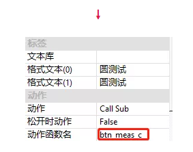
16. Add in main Add the function in the parameter setting interface when pressing the [circle test] button in the bas file, and associate the action function name.
  'Function of response when the circle measurement button is pressed on the parameter interface

  GLOBAL SUB btn_meas_c()

              btn_mc_test()'Measurement circle realization subfunction

          ZV_GRAYTORGB(grabImg, latch)'Before drawing graphics, you need to convert the gray image to RGB chart

          ZV_CIRCLE(latch, draw_circle(0),draw_circle(1),draw_circle(2), C_GREEN)'Draw circle

          ZV_LATCH(latch,0)'Display image results


  END SUB


  'Implementation of sub function of measuring circle

  GLOBAL SUB btn_mc_test()'Measuring circle


  ZVOBJECT mr_c, tmp

  if d_use_locator=0 then

      'Generate ring gauge

      ZV_MRGENCIRCLE(mr_c,d_roi_arc(0), d_roi_arc(1), d_roi_arc(2), d_roi_arc(3),d_roi_arc(4),d_roi_arc(5), 1, d_circle_parm(4),d_circle_parm(5))

  endif


  'Set the measurement parameters, including filter size, edge threshold, edge polarity and edge position

  ZV_MRSETADV(mr_c,d_circle_parm(3), d_circle_parm(2), d_circle_parm(0),d_circle_parm(1))


  'Initialize result array

  TABLE(586, 0, 0, 0)

  'Measure the circle and assign the result to the array with starting address 586

  ZV_MRCIRCLE(mr_c, grabImg, tmp, 586)


  'Assign a result variable to draw a graph

  draw_circle(0)=TABLE(586)

  draw_circle(1)=TABLE(587)

  draw_circle(2)=TABLE(588)

  if d_use_calib=1 and is_ca_success=1 then 'If the calibration function is used and the calibration has been successful


          ZV_CALTRANSW(ca_param, TABLE(586),TABLE(587),590) 'Pixel coordinates to world coordinates

          ZV_CALTRANSW(ca_param, TABLE(586)+TABLE(588),TABLE(587),592) 'Coordinates of circle center plus radius


          'Assign the calibration result variable to display the data result

          circle_result(0)=TABLE(590)

          circle_result(1)=TABLE(591)

          'The radius is equal to the distance between the center point of the circle and the point on the circle

          circle_result(2)=ZV_DISTPP(TABLE(590),TABLE(591),TABLE(592),TABLE(593))


          ZV_LATCH(grabImg, 0)


          RETURN

      endif


      'Assign a pixel result variable to display the data result

      circle_result(0)=TABLE(586)

      circle_result(1)=TABLE(587)

      circle_result(2)=TABLE(588)


  END SUB
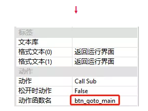
17. In main In the bas file, add the function that responds when the [return to operation interface] button is pressed in the parameter setting interface, and associate the action function name.
  'The function that responds when the return to operation button is pressed in the parameter setting interface

  GLOBAL SUB btn_goto_main()

      HMI_CLOSEWINDOW(11)

  END SUB
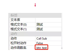
18. Add the function that responds when the [test] button is pressed in the operation interface, and associate the action function name.
  'Function to respond when the test button is pressed on the operation interface

      GLOBAL SUB btn_test()


          TICKS=0'Start timing

      if(d_use_locator=1) then 'If correction source is used


          btn_loc_test() 'location

      endif


      btn_measure_test() 'Measuring point/Line/circular

      d_detect_time=ABS(TICKS)'Calculate detection time consumption

  END SUB


  'Function to respond when the test button is pressed on the operation interface

  GLOBAL SUB btn_test()


          TICKS=0'Start timing

      if(d_use_locator=1) then 'If correction source is used

          btn_loc_test() 'location


      endif


      btn_measure_test() 'Measuring point/Line/circular

      d_detect_time=ABS(TICKS)'Calculate detection time consumption

  END SUB


  'Point line circle simultaneous test subfunction

  GLOBAL SUB btn_measure_test()


      if d_use_locator=1 then 'If correction source is used


          'Initialize the gauge

          ZV_MRGENRECT2(mr_p, d_roi_rect1(0), d_roi_rect1(1),d_roi_rect1(2), d_roi_rect1(3),d_roi_rect1(4), 1)

          ZV_MRGENLINE(mr_l,d_roi_rect2(0), d_roi_rect2(1),d_roi_rect2(2), d_roi_rect2(3), d_roi_rect2(4), 1,d_line_param(4),d_line_param(5))

          ZV_MRGENCIRCLE(mr_c,d_roi_arc(0), d_roi_arc(1), d_roi_arc(2), d_roi_arc(3),d_roi_arc(4),d_roi_arc(5), 1, d_circle_parm(4),d_circle_parm(5))


          'Calculating rigid transformation matrix

          ZV_GETRIGIDVECTOR(mat_rigid2, d_match_base_rst(1), d_match_base_rst(2), d_match_base_rst(3),TABLE(4),TABLE(5), d_match_rst(3))

          ZV_MRCORRECT (mr_p, mat_rigid2, mr_p) 'Correction of point measuring device

          ZV_MRCORRECT (mr_l, mat_rigid2, mr_l) 'Correction of line measuring device

          ZV_MRCORRECT (mr_c, mat_rigid2, mr_c) 'Correction of circular measuring instrument


      endif

      Point_measure() 'Measuring point

      btn_ml_test() 'Measuring line

      btn_mc_test() 'Measuring circle

      ZV_GRAYTORGB(grabImg, latch)

      ZV_MARKER(latch, draw_point(0), draw_point(1), 0, 20, C_BLUE)

      ZV_LINE(latch,draw_line(0),draw_line(1),draw_line(2),draw_line(3),C_BLUE)

      ZV_CIRCLE(latch, draw_circle(0),draw_circle(1),draw_circle(2), C_BLUE)

      ZV_LATCH(latch,0)


  END SUB
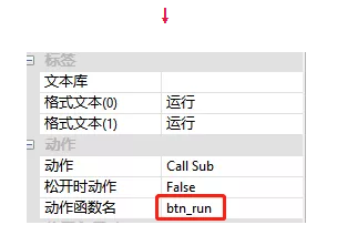
19. Add the function that responds when the [run] button is pressed in the operation interface, and associate the action function name.
  'Function to respond when the run button is pressed on the run interface

  GLOBAL SUB btn_run()


      if (1 = main_task_state) then

          if (0 = PROC_STATUS(main_task_id)) then

              main_task_state = 2

              RUNTASK main_task_id, main_task

          endif

      endif


  END SUB


  'Functions executed by the main task

  main_task:

      while(1)

          if (3 = main_task_state) then

              main_task_state = 1

              exit while

          endif


          'Continuously collect and operate the image

          btn_grab()

          btn_test()


      wend

  END
20. Add the function that responds when the [stop] button is pressed in the operation interface, and associate the action function name.
  'Function to respond when the stop button is pressed on the operation interface

  GLOBAL SUB btn_stop()


      if (2 = main_task_state) then

                      main_task_state = 3

      endif


  END SUB
02 simulation effect

This is the rapid movement of VPLC machine vision motion control machine (eight) - the measuring point / line / circle, which is shared here. More interesting content is concerned about the official account of "the little assistant for movement".
This article is original by positive motion technology. You are welcome to reprint it and learn together to improve China's intelligent manufacturing level. The copyright of this article belongs to rightmovement technology. If you reprint it, please indicate the source of the article.