RCC: reset clock control.
1. Main function of RCC - clock part
Set the system clock SYSCLK, set the AHB frequency division factor (determine how much HCLK is equal to), set the APB2 frequency division factor (determine how much PCLK2 is equal to), set the APB1 frequency division factor (determine how much PCLK1 is equal to), and set the frequency division factor of each peripheral; Control the start of the three bus clocks of AHB, APB2 and APB1 and the start of the clock of each peripheral. The configuration of SYSCLK, HCLK, PCLK2 and PCLK1 clocks is generally: PCLK2 = HCLK = SYSCLK = PLLCLK = 72M, PCLK1 = HCLK/2 = 36M. This clock configuration is also the standard configuration of library functions, which we use most.
2. RCC block diagram analysis - clock part
If the clock tree only talks about theory, it will be boring. If a main line is selected and supplemented by code, it will be easy to explain first and then second, and the memory will be more profound. Here we select the library clock system clock function: SetSysClockTo72(); Explain the clock tree with the writing process of this function. This function is also the default system clock setting function when we use the library. The function uses HSE to set the clock to PCLK2 = HCLK = SYSCLK = 72M, PCLK1 = HCLK/2 = 36M. Next, we will take the code flow as the main line to analyze the clock tree. The corresponding part is the yellow part in the figure. The code flow is identified in numerical order in the clock tree.
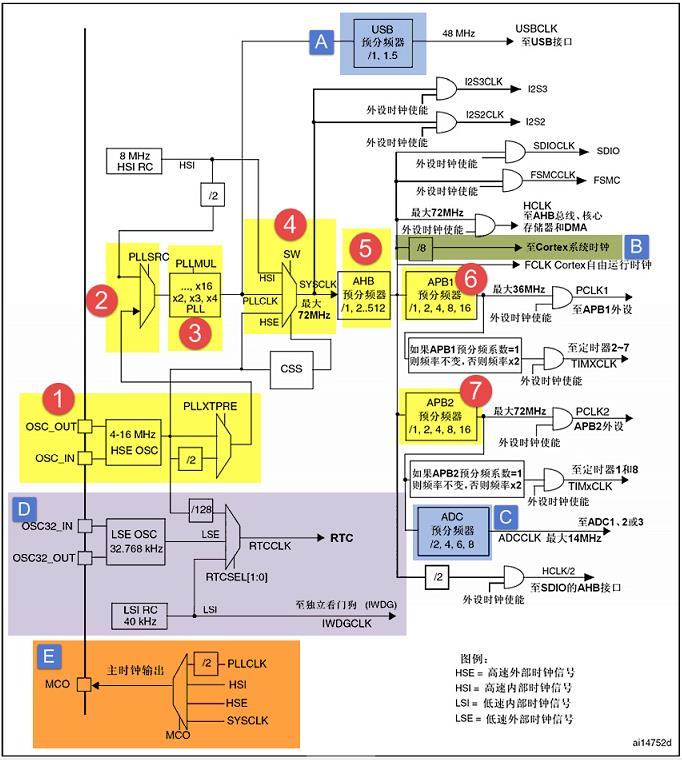
Figure 16-1 STM32 clock tree
2.1 system clock
① HSE high speed external clock signal
HSE is a high-speed external clock signal, which can be provided by active crystal oscillator or passive crystal oscillator, and the frequency ranges from 4 - 16MHZ. When an active crystal oscillator is used, the clock is transmitted from the OSC_IN pin entry, OSC_ The out pin is suspended. When a passive crystal oscillator is selected, the clock is switched from the OSC_IN and OSC_OUT enters and is equipped with resonant capacitor.
8M passive crystal oscillator is the most commonly used by HSE. When determining the source of PLL clock, HSE can not divide frequency or divide frequency 2. This is set by bit 17: PLLXTPRE of clock configuration register CFGR, and we set HSE not to divide frequency.
② PLL clock source
There can be two PLL clock sources, one from HSE and the other from HSI/2. Which is set by bit 16: PLLSRC of clock configuration register CFGR. HSI is an internal high-speed clock signal with a frequency of 8M. The frequency will drift according to the temperature and environment. It is generally not used as the clock source of PLL. Here we choose HSE as the clock source of PLL.
③ PLL clock PLLCLK
By setting the frequency doubling factor of PLL, the clock source of PLL can be frequency doubled. The frequency doubling factor can be: [2,3,4,5,6,7,8,9,10,11,12,13,14,15,16]. The specific setting is set by bits 21-18 of clock configuration register CFGR: PLLMUL[3:0]. We set it as 9-frequency multiplication here. In the last step, we set the clock source of PLL as HSE = 8M, so the PLL clock after PLL frequency multiplication: PLLCLK = 8M * 9 = 72M. 72M is the stable operation clock officially recommended by ST. if you want to overclock, you can increase the frequency doubling factor, up to 128M. We set the PLL clock here: PLLCLK = 8M * 9 = 72M.
④ System clock SYSCLK
The system clock sources can be HSI, PLLCLK and HSE. The specific clock configuration register CFGR is set with bit 1-0: SW[1:0]. We set the system clock here: SYSCLK = PLLCLK = 72M.
⑤ AHB bus clock HCLK
After the system clock SYSCLK is divided by the AHB prescaler, the clock is called APB bus clock, that is, HCLK. The frequency division factor can be: [1,2,4,8,16,64128256512]. Specifically, it is set by bits 7-4: HPRE[3:0] of the clock configuration register CFGR. The clocks of most peripherals on the chip are obtained by HCLK frequency division. As for the clock setting of peripherals on AHB bus, we have to wait until we use the peripherals. Here, we only need to set the clock of APB in bold lines. We set it here as 1 frequency division, that is, HCLK = SYSCLK = 72M.
⑥ APB1 bus clock HCLK1
APB1 bus clock PCLK1 is obtained by HCLK through low-speed APB prescaler. The frequency division factor can be: [1,2,4,8,16], which is determined by bits 10-8: PRRE1[2:0] of clock configuration register CFGR. HCLK1 is a low-speed bus clock with a maximum of 36M. On chip low-speed peripherals are attached to this bus, such as USART2/3/4/5, SPI2/3, I2C1/2, etc. As for the clock setting of the peripheral on the APB1 bus, it can only be set when we use the peripheral. Here, we only need to set the clock of APB1 in bold lines. We set it here as 2 frequency division, that is, PCLK1 = HCLK/2 = 36M.
⑦ APB2 bus clock HCLK2
APB2 bus clock PCLK2 is obtained by HCLK through high-speed APB2 prescaler. The frequency division factor can be: [1,2,4,8,16], which is determined by bits 13-11: PPRE2[2:0] of clock configuration register CFGR. HCLK2 is a high-speed bus clock. On chip high-speed peripherals are attached to this bus, such as all GPIO, USART1, SPI1, etc. As for the clock setting of the peripheral on the APB2 bus, it can only be set when we use the peripheral. We only need to set the clock of APB2 in bold lines. We set it here as 1 frequency division, that is, PCLK2 = HCLK = 72M.
Set system clock library function
The system clock library function corresponding to the above seven steps is as follows, which is intercepted from the firmware library file system_stm32f10x.c. In order to facilitate reading, I have deleted the code related to the interconnection type, translated the English notes into Chinese, and marked the code with serial number, a total of seven steps. This function directly operates the register. For the register part, please refer to the register description part of RCC in the data manual.
Code 16-1 setting system clock library function
static void SetSysClockTo72(void)
{
    __IO uint32_t StartUpCounter = 0, HSEStatus = 0;

    // ① Enable HSE and wait for HSE stability
    RCC->CR |= ((uint32_t)RCC_CR_HSEON);

    // Wait for the HSE startup to be stable and handle the timeout
    do
    {
        HSEStatus = RCC->CR & RCC_CR_HSERDY;
        StartUpCounter++;
    }
    while ((HSEStatus == 0) && (StartUpCounter != HSE_STARTUP_TIMEOUT));

    if ((RCC->CR & RCC_CR_HSERDY) != RESET)
    {
        HSEStatus = (uint32_t)0x01;
    }
    else
    {
        HSEStatus = (uint32_t)0x00;
    }
    // If HSE is started successfully, continue to deal with it
    if (HSEStatus == (uint32_t)0x01)
    {

        //-----------------------------------------------------------
        // Enable FLASH pre access buffer*/
        FLASH->ACR |= FLASH_ACR_PRFTBE;

        // The ratio of SYSCLK cycle to flash memory access time is set to 2
        // When it is set to 2, SYSCLK can work when it is lower than 48M. If it is set to 0 or 1,
        // If the configured SYSCLK is out of range, a hardware error will occur and the program will die
        // 0:  0 < SYSCLK <= 24M
        // 0:  0 < SYSCLK <= 24M
        // 2:  48< SYSCLK <= 72M */
        FLASH->ACR &= (uint32_t)((uint32_t)~FLASH_ACR_LATENCY);
        FLASH->ACR |= (uint32_t)FLASH_ACR_LATENCY_2;
        //------------------------------------------------------------

        // ② Set AHB, APB2, APB1 prescaler factor
        // HCLK = SYSCLK
        RCC->CFGR |= (uint32_t)RCC_CFGR_HPRE_DIV1;
        // PCLK2 = HCLK
        RCC->CFGR |= (uint32_t)RCC_CFGR_PPRE2_DIV1;
        // PCLK1 = HCLK/2
        RCC->CFGR |= (uint32_t)RCC_CFGR_PPRE1_DIV2;

        // ③ Set PLL clock source and PLL frequency doubling factor, PLLCLK = HSE * 9 = 72 MHz
        RCC->CFGR &= (uint32_t)((uint32_t)
                                ~(RCC_CFGR_PLLSRC
                                  | RCC_CFGR_PLLXTPRE
                                  | RCC_CFGR_PLLMULL));
        RCC->CFGR |= (uint32_t)(RCC_CFGR_PLLSRC_HSE
                                | RCC_CFGR_PLLMULL9);

        // ④ Enable PLL
        RCC->CR |= RCC_CR_PLLON;

        // ⑤ Wait for PLL to stabilize
        while ((RCC->CR & RCC_CR_PLLRDY) == 0)
        {
        }

        // ⑥ Select PLL as the system clock source
        RCC->CFGR &= (uint32_t)((uint32_t)~(RCC_CFGR_SW));
        RCC->CFGR |= (uint32_t)RCC_CFGR_SW_PLL;

        // ⑦ Read the clock switching status bit and ensure that PLLCLK is selected as the system clock
        while ((RCC->CFGR&(uint32_t)RCC_CFGR_SWS) != (uint32_t)0x08)
        {
        }
    }
    else
    {
		// If HSE startup fails, the user can add the error code here
	}
}
2.2 other clocks
Through the explanation of the system clock setting, we have grasped 60% or 70% of the whole clock tree, and we will explain several important aspects of the rest of the clock.
2.2.1 USB clock
The USB clock is obtained by PLLCLK through the USB prescaler. The frequency division factor can be: [1,1.5]. Specifically, it is configured by bit 22: USBPRE of the clock configuration register CFGR. The maximum clock of USB is 48M. According to the frequency division factor, PLLCLK can only be 48M or 72M. Generally, we set PLLCLK = 72M and USBCLK = 48M. USB has high requirements for clock, so PLLCLK can only be obtained by HSE frequency doubling, and HSI frequency doubling cannot be used.
2.2.2 Cortex system clock
The Cortex system clock is obtained by HCLK 8 frequency division, which is equal to 9M. The Cortex system clock is used to drive the system timer SysTick of the kernel. SysTick is generally used for the clock beat of the operating system, and can also be used as ordinary timing.
2.2.3 ADC clock
The ADC clock is obtained by PCLK2 through the ADC prescaler, and the frequency division factor can be [2,4,6,8]. Specifically, it is determined by bits 15-14: ADCPRE[1:0] of the clock configuration register CFGR. It's strange that there is no 1 frequency division. The ADC clock can only be 14M at most. If the sampling period is set to the shortest 1.5 cycles, the ADC conversion time can reach the shortest 1us. If you really want to achieve the shortest conversion time of 1us, the clock of ADC must be 14M. The clock of reverse PCLK2 can only be 28M, 56M, 84M and 112M. Since the maximum of PCLK2 is 72M, only 28M and 56M can be taken.
2.2.4 RTC clock and independent watchdog clock
RTC clock can be obtained by HSE/128 frequency division, provided by low-speed external clock signal LSE with a frequency of 32.768KHZ, or provided by low-speed internal clock signal HSI. Which clock is configured by bits 9-8: RTCSEL[1:0] of backup domain control register BDCR. The clock of the independent watchdog is provided by the LSI and can only be provided by the LSI. The LSI is a low-speed internal clock signal with frequencies ranging from 30 to 60KHZ, generally 40KHZ.
2.2.5 MCO clock output
MCO is the abbreviation of microcontroller clock output. It is the clock output pin of microcontroller. It is multiplexed by PA8 in STM32 F1 series. Its main function is to provide external clock, which is equivalent to an active crystal oscillator. The clock sources of MCO can be PLLCLK/2, HSI, HSE and SYSCLK. The specific choice is determined by bits 26-24: MCO[2:0] of clock configuration register CFGR. In addition to providing external clock, we can also monitor the clock output of MCO pin through oscilloscope to verify whether our system clock configuration is correct.
3. Configure system clock test
3.1 use of HSE
Generally, we use HSE as the system clock after PLL frequency doubling. The usual configuration is: HSE = 8M, PLL frequency doubling factor: 9, and the system clock is set to: SYSCLK = 8M * 9 = 72M. Using HSE, the maximum SYSCLK of the system clock is 128M. This is what the library function we use does. Before the program comes to the main function, start the file: status_ stm32f10x_ hd. S has called the SystemInit() function to initialize the system clock to 72MHZ. SystemInit() is in the library file: system_stm32f10x.c. If we want to set the system clock lower or overclock, we can modify the underlying library file, but in order to maintain the integrity of the library, we can write one according to the clock tree process.
3.2 use of HSI
In case of HSE failure, if the clock source of PLL is HSE, not only HSE cannot be used, but also PLL will be closed. At this time, the system will automatically switch HSI as the system clock. At this time, SYSCLK = HSI = 8M. If CSS is not turned on and CSS is interrupted, the whole system can only operate at a low rate, This is a system. It's no different from paralysis. If the CSS function is enabled, remedial measures can be taken in the CSS interrupt in case of HSE failure, use HSI, and set the system clock to a higher frequency, up to 64M. The frequency of 64M is enough for general peripherals, such as ADC, SPI, I2C, etc. However, there is another problem here. The original SYSCLK = 72M, but now it is changed to 64M because of the fault, the clocks of those peripherals must have been changed, and the work of peripherals will be disrupted. When setting the HSI clock, do we also readjust the frequency division factor of the peripheral bus, that is, the frequency division factor of AHB, APB2 and APB1, Make the clock of peripherals reach the same level as before HSE has no fault. However, this is not the most guaranteed method. After all, HSI cannot be used all the time, so alarm measures should be taken in case of HSE failure.
In another case, some users don't want to use HSE and want to use HSI, but they don't know how to use HSI to set the system clock, because calling library functions uses HSE. Below, we give an example of using HSI to configure the system clock.
3.3 hardware design
① RCC
② One LED
RCC is the internal resource of MCU and does not need external circuit. The effect of different system clock frequencies on software delay can be judged intuitively through the flashing frequency of LED.
3.4 software design
We write two RCC driver files, bsp_clkconfig.h and bsp_clkconfig.c. It is used to store the RCC system clock configuration function.
3.4.1 key points of programming
The programming points correspond to the serial numbers in the clock tree.
① Start HSE/HSI and wait for HSE/HSI to stabilize
② Set the prescaler factor of AHB, APB2 and APB1
③ Set the clock source of PLL and the frequency doubling factor of PLL. Setting various frequencies is mainly set here
④ Turn on the PLL and wait for the PLL to stabilize
⑤ Switch PLLCK to SYSCLK
⑥ Read the clock switching status bit and ensure that PLLCLK is selected as the system clock
3.4.2 code analysis
Configuring the system clock using HSE
Code 16-2 HSE as system clock source
void HSE_SetSysClock(uint32_t pllmul)
{
    IO uint32_t StartUpCounter = 0, HSEStartUpStatus = 0;

    // Initialize the RCC peripheral to the reset state
    RCC_DeInit();

    // Enable HSE and turn on the external crystal oscillator. The wild fire STM32F103 series development board uses 8M
    RCC_HSEConfig(RCC_HSE_ON);

    // Wait for HSE startup to be stable
    HSEStartUpStatus = RCC_WaitForHSEStartUp();

    // Only after HSE is stable, continue to implement
    if (HSEStartUpStatus == SUCCESS)
    {
//-----------------------------------------------------------------//
        // These two sentences are used to operate FLASH. If FLASH is not operated, it will not affect the comment of these two sentences
        // Enable FLASH pre access buffer
        FLASH_PrefetchBufferCmd(FLASH_PrefetchBuffer_Enable);

        // The ratio of SYSCLK cycle to flash memory access time is set to 2
        // When it is set to 2, SYSCLK can work when it is lower than 48M. If it is set to 0 or 1,
        // If the configured SYSCLK is out of range, a hardware error will occur and the program will die
        // 0:  0 < SYSCLK <= 24M
        // 1:  24< SYSCLK <= 48M
        // 2:  48< SYSCLK <= 72M
        FLASH_SetLatency(FLASH_Latency_2);
//-----------------------------------------------------------------//

        // AHB prescaler factor is set to 1, HCLK = SYSCLK
        RCC_HCLKConfig(RCC_SYSCLK_Div1);

        // APB2 prescaler factor is set to 1, PCLK2 = HCLK
        RCC_PCLK2Config(RCC_HCLK_Div1);

        // APB1 prescaler factor is set to 1, PCLK1 = HCLK/2
        RCC_PCLK1Config(RCC_HCLK_Div2);

//-----------------Setting various frequencies is mainly set here-------------------//
        // Set the PLL clock source as HSE and set the PLL frequency doubling factor
        // PLLCLK = 8MHz * pllmul
        RCC_PLLConfig(RCC_PLLSource_HSE_Div1, pllmul);
//-------------------------------------------------------------//

        // Turn on PLL
        RCC_PLLCmd(ENABLE);

        // Wait for PLL to stabilize
        while (RCC_GetFlagStatus(RCC_FLAG_PLLRDY) == RESET)
        {
        }

        // When the PLL is stable, switch the PLL clock to the system clock SYSCLK
        RCC_SYSCLKConfig(RCC_SYSCLKSource_PLLCLK);

        // Read the clock switching status bit and ensure that PLLCLK is selected as the system clock
        while (RCC_GetSYSCLKSource() != 0x08)
        {
        }
    }
    else
    {
        // If the HSE startup fails, the program will come here, and the user can add the wrong code here
        // When HSE startup fails or fails, the single chip microcomputer will automatically set HSI as the system clock,
        // HSI is an internal high-speed clock, 8MHZ
        while (1)
        {
        }
    }
}
This function is written by library function. The function has a formal parameter pllmul, which is used to set the frequency doubling factor of PLL. When calling, the formal parameter can be RCC_ PLLMul_ X, X: [2,3,... 16], these macros are derived from the definition of library functions. Macro expansion is some 32-bit hexadecimal numbers. The specific function is to configure bits 21-18 PLLMUL[3:0] of clock configuration register CFGR, and pre-defined frequency multiplication factor for easy calling.
Function call example: HSE_SetSysClock(RCC_PLLMul_9); Then set the system clock as 8MHZ * 9 = 72MHZ. HSE_SetSysClock(RCC_PLLMul_16); Then set the system clock as 8MHZ * 16 = 128MHZ. Use with caution when overclocking.
Configuring the system clock using HSI
void HSI_SetSysClock(uint32_t pllmul)
{
    IO uint32_t HSIStartUpStatus = 0;

    // Initialize the RCC peripheral to the reset state
    RCC_DeInit();

    // Enable HSI
    RCC_HSICmd(ENABLE);

    // Wait for HSI ready
    HSIStartUpStatus = RCC->CR & RCC_CR_HSIRDY;

    // Proceed only after HSI is ready
    if (HSIStartUpStatus == RCC_CR_HSIRDY)
    {
        //-------------------------------------------------------------//
        // These two sentences are used to operate FLASH. If FLASH is not operated, it will not affect the comment of these two sentences
        // Enable FLASH pre access buffer
        FLASH_PrefetchBufferCmd(FLASH_PrefetchBuffer_Enable);

        // The ratio of SYSCLK cycle to flash memory access time is set to 2
        // When it is set to 2, SYSCLK can work when it is lower than 48M. If it is set to 0 or 1,
        // If the configured SYSCLK is out of range, a hardware error will occur and the program will die
        // 0:  0 < SYSCLK <= 24M
        // 1:  24< SYSCLK <= 48M
        // 2:  48< SYSCLK <= 72M
        FLASH_SetLatency(FLASH_Latency_2);
        //------------------------------------------------------------//

        // AHB prescaler factor is set to 1, HCLK = SYSCLK
        RCC_HCLKConfig(RCC_SYSCLK_Div1);

        // APB2 prescaler factor is set to 1, PCLK2 = HCLK
        RCC_PCLK2Config(RCC_HCLK_Div1);

        // APB1 prescaler factor is set to 1, PCLK1 = HCLK/2
        RCC_PCLK1Config(RCC_HCLK_Div2);

        //-----------Setting various frequencies is mainly set here-------------------//
        // Set the PLL clock source as HSE and set the PLL frequency doubling factor
        // PLLCLK = 4MHz * pllmul
        RCC_PLLConfig(RCC_PLLSource_HSI_Div2, pllmul);
        //-------------------------------------------------------//

        // Turn on PLL
        RCC_PLLCmd(ENABLE);

        // Wait for PLL to stabilize
        while (RCC_GetFlagStatus(RCC_FLAG_PLLRDY) == RESET)
        {
        }

        // When the PLL is stable, switch the PLL clock to the system clock SYSCLK
        RCC_SYSCLKConfig(RCC_SYSCLKSource_PLLCLK);

        // Read the clock switching status bit and ensure that PLLCLK is selected as the system clock
        while (RCC_GetSYSCLKSource() != 0x08)
        {
        }
    }
    else
    {
        // If the HSI fails to start, the program will come here, and the user can add the wrong code here
        // When HSE startup fails or fails, the single chip microcomputer will automatically set HSI as the system clock,
        // HSI is an internal high-speed clock, 8MHZ
        while (1)
        {
        }
    }
}
The principle of HSI setting system clock function is the same as that of HSE setting system clock function. One difference is that HSI must be 2 divided before it can be used as the clock source of PLL. Therefore, when HSI is used, the maximum system clock SYSCLK can only be HSI / 2 * 16 = 4 * 16 = 64MHZ.
Function call example: HSI_SetSysClock(RCC_PLLMul_9); Then set the system clock as 4MHZ * 9 = 36MHZ.
Software delay
void Delay(__IO uint32_t nCount)
{
    for (; nCount != 0; nCount--);
}
The software delay function uses different system clocks, and the delay time is different, which can be judged by the flashing frequency of LED.
MCO output
In STM32F103 series, PA8 can be reused as MCO pin to provide external clock output. We can also monitor the output of this pin with oscilloscope to judge whether our system clock is set correctly.
Code 16-3 MCO GPIO initialization
/*
	* Initialize MCO pin PA8
	* In F103 series, there is only one MCO pin, PA8. In F4 series, there are two MCO pins
*/
void MCO_GPIO_Config(void)
{
    GPIO_InitTypeDef GPIO_InitStructure;
    // Turn on the clock of GPIOA
    RCC_APB2PeriphClockCmd(RCC_APB2Periph_GPIOA, ENABLE);

    // Select GPIO8 pin
    GPIO_InitStructure.GPIO_Pin = GPIO_Pin_8;

    // Set as push-pull output of multiplexing function
    GPIO_InitStructure.GPIO_Mode = GPIO_Mode_AF_PP;

    // Set the turnover rate of IO to 50M
    GPIO_InitStructure.GPIO_Speed = GPIO_Speed_50MHz;

    // Initialize GPIOA8
    GPIO_Init(GPIOA, &GPIO_InitStructure);
}
Code 16-4 MCO output clock selection
// Set the MCO pin output clock, and the output clock signal can be measured on PA8 with an oscilloscope,
// We can use PLLCLK/2 as the clock of MCO pin to check whether the system clock is configured accurately
// MCO pin outputs can be HSE,HSI,PLLCLK/2,SYSCLK
// RCC_MCOConfig(RCC_MCO_HSE);
// RCC_MCOConfig(RCC_MCO_HSI);
// RCC_MCOConfig(RCC_MCO_PLLCLK_Div2);
RCC_MCOConfig(RCC_MCO_SYSCLK);
After initializing the MCO pin, we can directly call the library function RCC_MCOConfig() to select the MCO clock source.
Main function
int main(void)
{
    // Before the program comes to the main function, start the file: status_ stm32f10x_ hd. S has been called
    // The SystemInit() function initializes the system clock to 72MHZ
    // SystemInit() in system_ stm32f10x. Defined in C
    // If you want to modify the system clock, you can write your own program to modify it

    // Reset the system clock. At this time, you can choose to use HSE or HSI

    // When using HSE, sysclk = 8m * RCC_ PLLMul_ x. X: [2,3,... 16], up to 128M
    HSE_SetSysClock(RCC_PLLMul_9);

    // When using HSI, sysclk = 4m * RCC_ PLLMul_ x. X: [2,3,... 16], up to 64MH
    //HSI_SetSysClock(RCC_PLLMul_16);

    // MCO pin initialization
    MCO_GPIO_Config();

    // Set the MCO pin output clock, and the output clock signal can be measured on PA8 with an oscilloscope,
    // We can use PLLCLK/2 as the clock of MCO pin to check whether the system clock is configured accurately
    // MCO pin outputs can be HSE,HSI,PLLCLK/2,SYSCLK
    // RCC_MCOConfig(RCC_MCO_HSE);
    // RCC_MCOConfig(RCC_MCO_HSI);
    // RCC_MCOConfig(RCC_MCO_PLLCLK_Div2);
    RCC_MCOConfig(RCC_MCO_SYSCLK);

    // LED port initialization
    LED_GPIO_Config();
    while (1)
    {
        LED1( ON ); // bright
        Delay(0x0FFFFF);
        LED1( OFF ); // Extinguish
        Delay(0x0FFFFF);
    }
}
In the main function, HSE can be called_ Setsysclock() or HSI_SetSysClock() sets the system clock to various common clocks, and then monitors it through MCO pin, or experiences the impact of different system clocks on the same software delay function through the speed of LED flashing.
3.4.3 code sorting
bsp_led.h
#ifndef __LED_H
#define	__LED_H


#include "stm32f10x.h"


void LED_Init(void);
void LED0_Level(unsigned char Level);


#endif /* __LED_H */
bsp_led.c
#include "bsp_led.h"


/*******************************************************************************
* Function name: LED_Init
* Function function 		   :  LED initialization function
* Input: None
* Output: None
* say 	 bright 		   :  nothing
*******************************************************************************/
void LED_Init(void)
{
	GPIO_InitTypeDef GPIO_InitStructure;

	RCC_APB2PeriphClockCmd(RCC_APB2Periph_GPIOB, ENABLE); // Enable PB port clock
	GPIO_InitStructure.GPIO_Pin=GPIO_Pin_5;			// LED0-->PB. 5 port configuration
	GPIO_InitStructure.GPIO_Mode=GPIO_Mode_Out_PP;	// Push pull output
	GPIO_InitStructure.GPIO_Speed=GPIO_Speed_50MHz;	// The speed of IO port is 50MHz
	GPIO_Init(GPIOB,&GPIO_InitStructure); 	   		// Initialize gpiob according to the set parameters five
	GPIO_SetBits(GPIOB,GPIO_Pin_5);					// PB.5 output high
}


/*******************************************************************************
* Function name: LED0_Level
* Function function 		   :  LED0 - IO level output
* Input: Level: 1 - output high; 	 0 - output low
* Output: None
* say 	 bright 		   :  nothing
*******************************************************************************/
void LED0_Level(unsigned char Level)
{
	if (Level == 1)
	{
		// PB.5 output high
		GPIO_SetBits(GPIOB,GPIO_Pin_5);
	}
	else if (Level == 0)
	{
		// PB.5 Output Low
		GPIO_ResetBits(GPIOB,GPIO_Pin_5);
	}
}
bsp_mcooutput.h
#ifndef __MCOOUTPUT_H
#define	__MCOOUTPUT_H


#include "stm32f10x.h"


void MCO_GPIO_Config(void);


#endif /* __MCOOUTPUT */
bsp_mcooutput.c
#include "bsp_mcooutput.h"


/*******************************************************************************
* Function name: MCO_GPIO_Config
* Function function 		   :  Initialize MCO pin PA8 function
* Input: None
* Output: None
* say 	 bright 		   :  In F1 series, there is only one MCO pin, namely PA8. In F4 series, there will be two MCO pins
*******************************************************************************/
void MCO_GPIO_Config(void)
{
	GPIO_InitTypeDef GPIO_InitStructure;

	// Turn on the clock of GPIOA
	RCC_APB2PeriphClockCmd(RCC_APB2Periph_GPIOA, ENABLE);
	// Select GPIO8 pin
	GPIO_InitStructure.GPIO_Pin = GPIO_Pin_8;
	//Set as push-pull output of multiplexing function
	GPIO_InitStructure.GPIO_Mode = GPIO_Mode_AF_PP;
	//Set the turnover rate of IO to 50M
	GPIO_InitStructure.GPIO_Speed = GPIO_Speed_50MHz;
	// Initialize GPIOA8
	GPIO_Init(GPIOA, &GPIO_InitStructure);
}
bsp_clkconfig.h
#ifndef __CLKCONFIG_H
#define	__CLKCONFIG_H


#include "stm32f10x.h"
#include "stm32f10x_rcc.h"


void HSE_SetSysClock(uint32_t pllmul);
void HSI_SetSysClock(uint32_t pllmul);


#endif /* __CLKCONFIG_H */
bsp_clkconfig.c
#include "bsp_clkconfig.h"


/*
 * Steps to set the system clock when using HSE
 * 1,Start HSE and wait for HSE to stabilize
 * 2,Set the prescaler factor of AHB, APB2 and APB1
 * 3,Set the clock source of PLL and the frequency doubling factor of PLL. Setting various frequencies is mainly set here
 * 4,Turn on the PLL and wait for the PLL to stabilize
 * 5,Switch PLLCK to SYSCLK
 * 6,Read the clock switching status bit and ensure that PLLCLK is selected as the system clock
 */

/* Set system clock: SYSCLK, AHB bus clock: HCLK, APB2 bus clock: PCLK2, APB1 bus clock: PCLK1
 * PCLK2 = HCLK = SYSCLK
 * PCLK1 = HCLK/2,The maximum can only be 36M
 * Parameter Description: pllmul is the frequency doubling factor of PLL. It can be RCC when calling_ PLLMul_ x , x:[2,3,...16]
 * Example: User_SetSysClock(RCC_PLLMul_9);   Then set the system clock as 8MHZ * 9 = 72MHZ
 *       User_SetSysClock(RCC_PLLMul_16); Then set the system clock as 8MHZ * 16 = 128MHZ. Use it with caution when overclocking
 *
 * HSE As the clock source, PLL frequency doubling is used as the system clock, which is a common practice
 */


/* Set system clock: SYSCLK, AHB bus clock: HCLK, APB2 bus clock: PCLK2, APB1 bus clock: PCLK1
 * PCLK2 = HCLK = SYSCLK
 * PCLK1 = HCLK/2,The maximum can only be 36M
 * Parameter Description: pllmul is the frequency doubling factor of PLL. It can be RCC when calling_ PLLMul_ x , x:[2,3,...16]
 * Example: HSE_SetSysClock(RCC_PLLMul_9);   Then set the system clock as 8MHZ * 9 = 72MHZ
 *       HSE_SetSysClock(RCC_PLLMul_16); Then set the system clock as 8MHZ * 16 = 128MHZ. Use it with caution when overclocking
 *
 * HSE As the clock source, PLL frequency doubling is used as the system clock, which is a common practice
 */
void HSE_SetSysClock(uint32_t pllmul)
{
	__IO uint32_t StartUpCounter = 0, HSEStartUpStatus = 0;

	// It is necessary to initialize the RCC peripheral to the reset state
	RCC_DeInit();

	//Enable HSE and turn on the external crystal oscillator. 8M is used for wildfire development board
	RCC_HSEConfig(RCC_HSE_ON);

	// Wait for HSE startup to be stable
	HSEStartUpStatus = RCC_WaitForHSEStartUp();

	// Only after HSE is stable, continue to implement
	if (HSEStartUpStatus == SUCCESS)
	{
		//----------------------------------------------------------------------//
		// Enable FLASH pre access buffer
		// FLASH_PrefetchBufferCmd(FLASH_PrefetchBuffer_Enable);

		// The ratio of SYSCLK cycle to flash memory access time is set to 2
		// When it is set to 2, SYSCLK can work when it is lower than 48M. If it is set to 0 or 1,
		// If the configured SYSCLK is out of range, a hardware error will occur and the program will die
		// 0: 0 < SYSCLK <= 24M
		// 1: 24< SYSCLK <= 48M
		// 2: 48< SYSCLK <= 72M
		FLASH_SetLatency(FLASH_Latency_2);
		//----------------------------------------------------------------------//

		// AHB prescaler factor is set to 1, HCLK = SYSCLK
		RCC_HCLKConfig(RCC_SYSCLK_Div1);

		// APB2 prescaler factor is set to 1, PCLK2 = HCLK
		RCC_PCLK2Config(RCC_HCLK_Div1);

		// APB1 prescaler factor is set to 1, PCLK1 = HCLK/2
		RCC_PCLK1Config(RCC_HCLK_Div2);

		//-----------------Setting various frequencies is mainly set here-------------------//
		// Set the PLL clock source as HSE and set the PLL frequency doubling factor
		// PLLCLK = 8MHz * pllmul
		RCC_PLLConfig(RCC_PLLSource_HSE_Div1, pllmul);
		//------------------------------------------------------------------//

		// Turn on PLL
		RCC_PLLCmd(ENABLE);

		// Wait for PLL to stabilize
		while (RCC_GetFlagStatus(RCC_FLAG_PLLRDY) == RESET)
		{
		}

		// When the PLL is stable, switch the PLL clock to the system clock SYSCLK
		RCC_SYSCLKConfig(RCC_SYSCLKSource_PLLCLK);

		// Read the clock switching status bit and ensure that PLLCLK is selected as the system clock
		while (RCC_GetSYSCLKSource() != 0x08)
		{
		}
	}
	else
	{
		// If the HSE startup fails, the program will come here, and the user can add the wrong code here
		// When HSE startup fails or fails, the single chip microcomputer will automatically set HSI as the system clock,
		// HSI is an internal high-speed clock, 8MHZ
		while (1)
		{
		}
	}
}


/*
 * To set the system clock when using HSI
 * 1,Turn on the HSI and wait for the HSI to stabilize
 * 2,Set the prescaler factor of AHB, APB2 and APB1
 * 3,Set the clock source of PLL and the frequency doubling factor of PLL. Setting various frequencies is mainly set here
 * 4,Turn on the PLL and wait for the PLL to stabilize
 * 5,Switch PLLCK to SYSCLK
 * 6,Read the clock switching status bit and ensure that PLLCLK is selected as the system clock
 */

/* Set system clock: SYSCLK, AHB bus clock: HCLK, APB2 bus clock: PCLK2, APB1 bus clock: PCLK1
 * PCLK2 = HCLK = SYSCLK
 * PCLK1 = HCLK/2,The maximum can only be 36M
 * Parameter Description: pllmul is the frequency doubling factor of PLL. It can be RCC when calling_ PLLMul_ x , x:[2,3,...16]
 * Example: HSI_SetSysClock(RCC_PLLMul_9);   Then set the system clock as 4MHZ * 9 = 72MHZ
 *       HSI_SetSysClock(RCC_PLLMul_16); Then set the system clock as 4MHZ * 16 = 64MHZ
 *
 * HSI As the clock source, PLL frequency doubling is used as the system clock, which is only used in case of HSE failure
 * HSI There will be drift and instability due to temperature and other reasons. Generally, HSI will not be used as the clock source unless it is forced
 * If HSI is to be used as the source of PLL clock, it can only be used after frequency division, that is, HSI/2, and the maximum PLL frequency doubling factor can only be 16
 * Therefore, when HSI is used, the maximum SYSCLK can only be 4M*16=64M
 */
void HSI_SetSysClock(uint32_t pllmul)
{
	__IO uint32_t HSIStartUpStatus = 0;

	// It is necessary to initialize the RCC peripheral to the reset state
	RCC_DeInit();

	//Enable HSI
	RCC_HSICmd(ENABLE);

	// Wait for HSI ready
	HSIStartUpStatus = RCC->CR & RCC_CR_HSIRDY;

	// Proceed only after HSI is ready
	if (HSIStartUpStatus == RCC_CR_HSIRDY)
	{
		//----------------------------------------------------------------------//
		// Enable FLASH pre access buffer
		// FLASH_PrefetchBufferCmd(FLASH_PrefetchBuffer_Enable);

		// The ratio of SYSCLK cycle to flash memory access time is set to 2
		// When it is set to 2, SYSCLK can work when it is lower than 48M. If it is set to 0 or 1,
		// If the configured SYSCLK is out of range, a hardware error will occur and the program will die
		// 0: 0 < SYSCLK <= 24M
		// 1: 24< SYSCLK <= 48M
		// 2: 48< SYSCLK <= 72M
		FLASH_SetLatency(FLASH_Latency_2);
		//----------------------------------------------------------------------//

		// AHB prescaler factor is set to 1, HCLK = SYSCLK
		RCC_HCLKConfig(RCC_SYSCLK_Div1);

		// APB2 prescaler factor is set to 1, PCLK2 = HCLK
		RCC_PCLK2Config(RCC_HCLK_Div1);

		// APB1 prescaler factor is set to 1, PCLK1 = HCLK/2
		RCC_PCLK1Config(RCC_HCLK_Div2);

		//-----------------Setting various frequencies is mainly set here-------------------//
		// Set the PLL clock source as HSE and set the PLL frequency doubling factor
		// PLLCLK = 4MHz * pllmul
		RCC_PLLConfig(RCC_PLLSource_HSI_Div2, pllmul);
		//------------------------------------------------------------------//

		// Turn on PLL
		RCC_PLLCmd(ENABLE);

		// Wait for PLL to stabilize
		while (RCC_GetFlagStatus(RCC_FLAG_PLLRDY) == RESET)
		{
		}

		// When the PLL is stable, switch the PLL clock to the system clock SYSCLK
		RCC_SYSCLKConfig(RCC_SYSCLKSource_PLLCLK);

		// Read the clock switching status bit and ensure that PLLCLK is selected as the system clock
		while (RCC_GetSYSCLKSource() != 0x08)
		{
		}
	}
	else
	{
		// If the HSI fails to start, the program will come here, and the user can add the wrong code here
		// When HSE startup fails or fails, the single chip microcomputer will automatically set HSI as the system clock,
		// HSI is an internal high-speed clock, 8MHZ
		while (1)
		{
		}
	}
}
delay.h
#ifndef __DELAY_H
#define __DELAY_H


#include "stm32f10x.h"


void Delay(__IO uint32_t nCount);


#endif
delay.c
#include "delay.h"


void Delay(__IO uint32_t nCount)	 //Simple delay function
{
	for(; nCount != 0; nCount--);
}
main.c
/*
 * Configure MCO pin: PA8 provides external clock, and the maximum frequency cannot exceed the flip frequency of IO port 50MHZ
 * MCO Clock sources can be pllclk / 2, HSI, HSE and sysclk
 */
#include "stm32f10x.h"
#include "bsp_led.h"
#include "bsp_clkconfig.h"
#include "bsp_mcooutput.h"
#include "delay.h"


/**
  * @brief  Main function
  * @param  nothing
  * @retval nothing
  */
int main(void)
{
	// Before the program comes to the main function, start the file: status_ stm32f10x_ hd. S has been called
	// The SystemInit() function initializes the system clock to 72MHZ
	// SystemInit() in system_ stm32f10x. Defined in C
	// If you want to modify the system clock, you can write your own program to modify it

	// Reset the system clock. At this time, you can choose to use HSE or HSI

	// When using HSE, sysclk = 8m * RCC_ PLLMul_ x. X: [2,3,... 16], up to 128M
	HSE_SetSysClock(RCC_PLLMul_9);

	// When using HSI, sysclk = 4m * RCC_ PLLMul_ x. X: [2,3,... 16], up to 64MH
	// HSI_SetSysClock(RCC_PLLMul_16);

	// MCO pin initialization
	MCO_GPIO_Config();

	// Set the MCO pin output clock, and the output clock signal can be measured on PA8 with an oscilloscope,
	// We can use PLLCLK/2 as the clock of MCO pin to check whether the system clock is configured accurately
	// MCO pin outputs can be HSE,HSI,PLLCLK/2,SYSCLK
	//RCC_MCOConfig(RCC_MCO_HSE);
	//RCC_MCOConfig(RCC_MCO_HSI);
	//RCC_MCOConfig(RCC_MCO_PLLCLK_Div2);
	RCC_MCOConfig(RCC_MCO_SYSCLK);

	// LED port initialization
	LED_Init();
	while (1)
	{
		LED0_Level(0);
		Delay(0x0FFFFF);
		LED0_Level(1);
		Delay(0x0FFFFF);
	}
}
3.4.3 precautions
① Firmware library files used
#include "stm32f10x_gpio.h"
#include "stm32f10x_rcc.h"
#include "stm32f10x_flash.h"
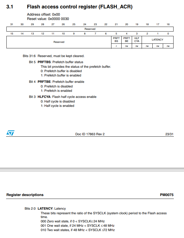
② FLASH_SetLatency(XXXX); This function must be set.
If the configured SYSCLK is out of range, a hardware error will occur and the program will die. This function is basically set to flash in most cases_ SetLatency(FLASH_Latency_2);
If flash is not configured_ SetLatency(XXXX); Or it can be configured as FLASH_SetLatency(FLASH_Latency_0); It is easy to get stuck in the lower position.
// Read the clock switching status bit and ensure that PLLCLK is selected as the system clock
while (RCC_GetSYSCLKSource() != 0x08)
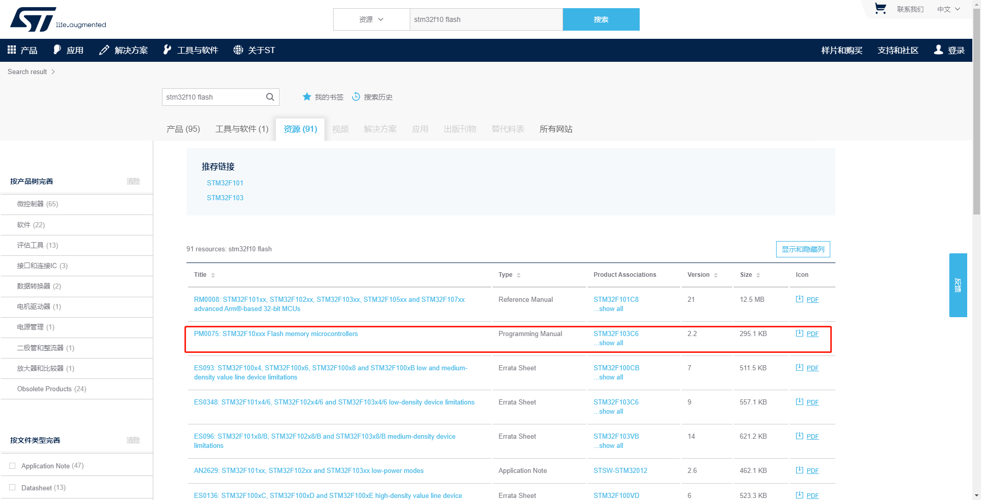
FLASH_ The setlatency (XXXX) function operates on the flash - > ACR register. This register is described in PM0075: STM32F10xxx Flash memory microcontrollers.PDF.