Project description of intelligent wifi car:
Two esp8266 are used to establish communication and mqtt protocol is added. The sender of esp8266 releases information by pressing the key (handle function). Esp8266 is used as the receiver to receive the information sent by the subscription topic and print the data through the serial port. stm32 is used as the main control to control the forward and backward of the two wheels, turn left and right, and perform the execution function of serial port reception
The complete project is divided into three modules
1. esp8266 transmitter (used to control the trolley) is similar to the remote control device
2. The esp8266 receiver (receiving the message from the sender) is similar to the receiving device
3. The main controller (stm32c8t6 for directly driving the trolley) executes the command
This project is the first module, and the development environment is Arduino
Description of module 1: on esp8266, mqtt protocol is used to release information to a certain topic. Four keys are connected externally. Different information is released to the topic through four keys. The four key pins are:
pinMode(16,INPUT); //key1
pinMode(5, INPUT); //key2
pinMode(4, INPUT); //key3
pinMode(0, INPUT); //key4
One side of the key is connected to the control terminal and the other side is connected to GND
The example code is as follows
Note: the project needs to import the esp8266 support package and PubSubClient library, which can be added
#include <ESP8266WiFi.h>
#include <PubSubClient.h>
#include <Ticker.h>

// Set WiFi access information (please modify according to your WiFi information)

const char* ssid = "iphone";//wifi account customization
const char* password = "112233445566";//wifi password customization
const char* mqttServer = "test.ranye-iot.net";//Connection public server address


Ticker ticker;
WiFiClient wifiClient;
PubSubClient mqttClient(wifiClient);

int count;    // Variable for Ticker counting

void setup() {
  Serial.begin(9600);

  pinMode(16,INPUT);   //key1
  pinMode(5, INPUT);   //key2
  pinMode(4, INPUT);   //key3
  pinMode(0, INPUT);   //key4

  // Ticker timing object
  ticker.attach(1, tickerCount);

  //Set the working mode of ESP8266 to wireless terminal mode
  WiFi.mode(WIFI_STA);

  // Connect WiFi
  connectWifi();

  // Set MQTT server and port number
  mqttClient.setServer(mqttServer, 1883);//The fixed port number is generally 1883
  mqttClient.setCallback(receiveCallback);

  // Connect to MQTT server
  connectMQTTServer();
}

void loop() {
  int i;

  if (mqttClient.connected()) { // If the development board successfully connects to the server
     pubMQTTmsg();
    mqttClient.loop();       // Keep your heart beating
  } else {                  // If the development board fails to connect to the server successfully
    connectMQTTServer();    // Then try to connect to the server
  }
}

void tickerCount(){
//  count++;
}

void connectMQTTServer(){
  // Generate the client ID according to the MAC address of ESP8266 (avoid the same name with the client ID of other ESP8266)
  String clientId = "esp8266-" + WiFi.macAddress();

  // Connect to MQTT server
  if (mqttClient.connect(clientId.c_str())) {
    Serial.println("MQTT Server Connected.");
    Serial.println("Server Address: ");
    Serial.println(mqttServer);
    Serial.println("ClientId:");
    Serial.println(clientId);
    subscribeTopic(); // Subscribe to the specified topic
  } else {
    Serial.print("MQTT Server Connect Failed. Client State:");
    Serial.println(mqttClient.state());
    delay(3000);
  }
}

// Release information
void pubMQTTmsg(){
  // Create a publishing topic. The topic name is prefixed with Taichi Maker -, followed by the MAC address of the device.
  // This is to ensure that the ESP8266 client names are different when different users publish MQTT information,
  String topicString = "Taichi-Maker-Pub-" + WiFi.macAddress();
  char publishTopic[topicString.length() + 1];
  strcpy(publishTopic, topicString.c_str());

  // Regularly publish the current D3(gpio0) pin status to the server topic
   String messageString;

   if(digitalRead(16)==LOW)
     messageString = "1";
   else if(digitalRead(5)==LOW)
     messageString = "2";
   else if(digitalRead(4)==LOW)
     messageString = "3";
   else if(digitalRead(0)==LOW)
     messageString = "4";
   else
     messageString = "0";

   delay(300);


/******************************************************************************************/
  char publishMsg[messageString.length() + 1];
  strcpy(publishMsg, messageString.c_str());

  // Implement ESP8266 to publish information to the subject
  if(mqttClient.publish(publishTopic, publishMsg)){
    Serial.println("Publish Topic:");Serial.println(publishTopic);
    Serial.println("Publish message:");Serial.println(publishMsg);
  } else {
    Serial.println("Message Publish Failed.");
  }
}

// Subscribe to the specified topic
void subscribeTopic(){

  // Create a subscription topic. The subject name is prefixed with Taichi maker sub, followed by the MAC address of the device.
  // This is to ensure that when different devices use the same MQTT server to test message subscription, the subscribed topic names are different
  String topicString = "Taichi-Maker-Sub-" + WiFi.macAddress();
  char subTopic[topicString.length() + 1];
  strcpy(subTopic, topicString.c_str());

  // Output whether the topic is successfully subscribed and the name of the subscribed topic through the serial port monitor
  if(mqttClient.subscribe(subTopic)){
    Serial.println("Subscribe Topic:");
    Serial.println(subTopic);
  } else {
    Serial.print("Subscribe Fail...");
  }
}

// Callback function after receiving information
void receiveCallback(char* topic, byte* payload, unsigned int length) {
  Serial.print("Message Received [");
  Serial.print(topic);
  Serial.print("] ");
  for (int i = 0; i < length; i++) {
    Serial.print((char)payload[i]);
  }
  Serial.println("");
  Serial.print("Message Length(Bytes) ");
  Serial.println(length);

  if ((char)payload[0] == '1') {     // If the received message starts with "1"
    digitalWrite(LED_BUILTIN,HIGH);  // The LED is illuminated.
  } else {
    digitalWrite(LED_BUILTIN, LOW); // Otherwise, turn off the LED.
  }
}

// ESP8266 connect wifi
void connectWifi(){

  WiFi.begin(ssid, password);

  //Wait for WiFi connection, and output success information after successful connection
  while (WiFi.status() != WL_CONNECTED) {
    delay(1000);
    Serial.print(".");
  }
  Serial.println("");
  Serial.println("WiFi Connected!");
  Serial.println("");
}
Through the above code, you can send information to a topic and print the published topic information through the serial port (9600)
After successful connection, WiFi Connected will be output once through the serial port!
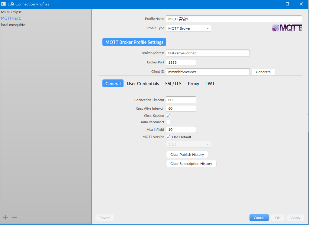
We can verify through MQTTfx software and join the same public network: test ranye-iot. net
The configuration is as follows:
Copy the theme printed on the serial port and add it to the theme to be subscribed
(the themes published by different development boards are inconsistent, and they shall be selected according to the themes printed by the serial port of their own development board)
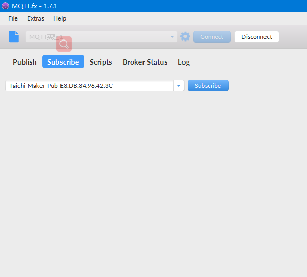
After you subscribe, you will continue to receive data - continue to print 0
Press the keys key1, key2, Key3 Key4, press to print different data, corresponding to 1, 2, 3 and 4 respectively
If no data is received,
1. Check whether esp8266 is connected to the network
2. Check whether the key wiring is correct
3. Check whether the mqttfx software is connected to the same public network, and the configuration shall be consistent with the figure above
4. Check whether the publishing topic is consistent with the subscription topic