Outputting debugging information is an indispensable debugging tool in embedded development. One feature of embedded development is that there is no operating system or file system, and the conventional method of printing log to file is basically not applicable.
The most commonly used is to output uart log through serial port, such as 51 single chip microcomputer. As long as the serial port drive is realized, it can be output through serial port.
Serial port this method is simple to realize. Most embedded chips have serial port function. However, such simple functions are sometimes not so easy to use, such as:
- How to print log when there is no serial driver for a newly obtained chip?
- In some applications, the timing requirements are relatively high, and the serial port output log takes too long. What should I do? Such as usb enumeration.
- Some bug s will appear during normal operation. What if they don't reappear when the serial port log is opened?
- If there is no serial port in some packages, or the serial port has been used for other purposes, how to output log?
This paper introduces how to print debugging information when single chip microcomputer has no serial port.
1 output log information to SRAM
To be exact, this is not to output log, but to see log in a way without using serial port. In the chip development stage, the simulator can be connected for debugging, and the break point method can be used for debugging, but if some operations cannot be interrupted, the breakpoint debugging cannot be used. At this time, you can consider printing the log into SRAM, and then check the log buffer in SRAM through the emulator after the whole operation, so as to realize indirect log output.
The test platform used in this paper is stm32f407 discovery, which is based on usb host experimental code. The principle is also common for other embedded platforms.
First, define a structure to print the log, as follows:
typedef struct {
   volatile u8     type;
   u8*             buffer;             /* log buffer Pointer*/
   volatile u32    write_idx;          /* log Write location*/
   volatile u32    read_idx;           /* log Read position*/
}log_dev;
Define a section of SRAM space as log buffer
static u8 log_buffer[LOG_MAX_LEN];
log buffer is a ring buffer. You can print logs indefinitely in a small buffer. The disadvantage is also obvious. If the log is not output in time, it will be overwritten by a new buffer. Buffer size is allocated according to SRAM size. 1kB is used here.
In order to facilitate the output parameters, the printf function is used to format the output. The following configuration is required.
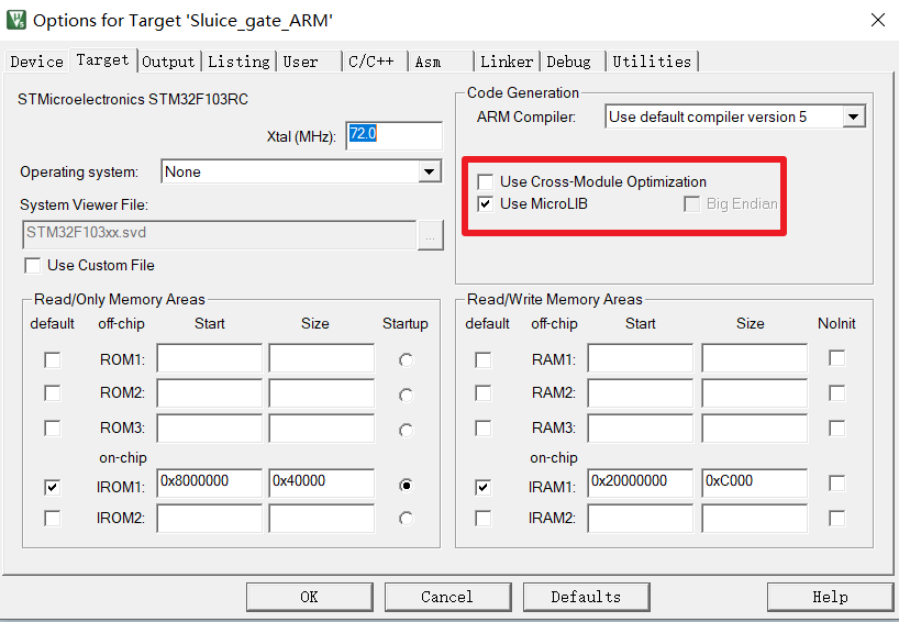
And include the header file #include < stdio h> , implement the function fputc() in the code.
//redirect fputc
int fputc(int ch, FILE *f)
{
    print_ch((u8)ch);
    return ch;
}
Write data to Sram:
/*write log to bufffer or I/O*/
void print_ch(u8 ch)
{
    log_dev_ptr->buffer[log_dev_ptr->write_idx++] = ch;
    if(log_dev_ptr->write_idx >= LOG_MAX_LEN){
        log_dev_ptr->write_idx = 0;
    }
}
To facilitate the control of log print format, add a user-defined print function in the header file:
#ifdef DEBUG_LOG_EN
#define DEBUG(...) printf("usb_printer:"__VA_ARGS__)
#else
#define DEBUG(...)
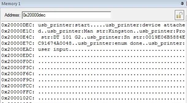
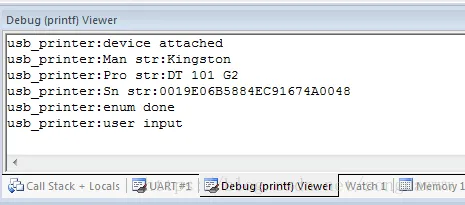
#endifCall DEBUG() directly where you need to print the log. The final effect is as follows. You can see the printed log from the Memory window:
Output log through SWO
The log can be seen by printing the log to SRAM, but it may be overwritten when there is a large amount of data. To solve this problem, you can use st link's SWO to output the log, so you don't have to worry about the log being overwritten.
Add the set of SWO operation functions in the log structure:
typedef struct{
    u8 (*init)(void* arg);
    u8 (*print)(u8 ch);
    u8 (*print_dma)(u8* buffer, u32 len);
}log_func;

typedef struct {
    volatile u8     type;
    u8*             buffer;
    volatile u32    write_idx;
    volatile u32    read_idx;
    //SWO
    log_func*       swo_log_func;
}log_dev;
SWO only needs the print operation function, which is implemented as follows:
u8 swo_print_ch(u8 ch)
{
    ITM_SendChar(ch);
    return 0;
}
Log output using SWO is also output to the log buffer first, and then output when the system is idle. Of course, it can also be output directly. The delayed output of log will affect the real-time performance of log, while the direct output will affect the operation of time-sensitive code, so how to choose depends on the situation where log needs to be output. Calling output_ in the while loop Ch() function, you can output log when the system is idle.
/*output log buffer to I/O*/
void output_ch(void)
{
    u8 ch;
    volatile u32 tmp_write,tmp_read;
    tmp_write = log_dev_ptr->write_idx;
    tmp_read = log_dev_ptr->read_idx;

    if(tmp_write != tmp_read){
            ch = log_dev_ptr->buffer[tmp_read++];
            //swo
            if(log_dev_ptr->swo_log_func)
                    log_dev_ptr->swo_log_func->print(ch);
            if(tmp_read >= LOG_MAX_LEN){
                    log_dev_ptr->read_idx = 0;
            }else{
                    log_dev_ptr->read_idx = tmp_read;
            }
    }
}
1 output through IDE
The following configuration (Keil) is required to use the SWO output function in IDE:
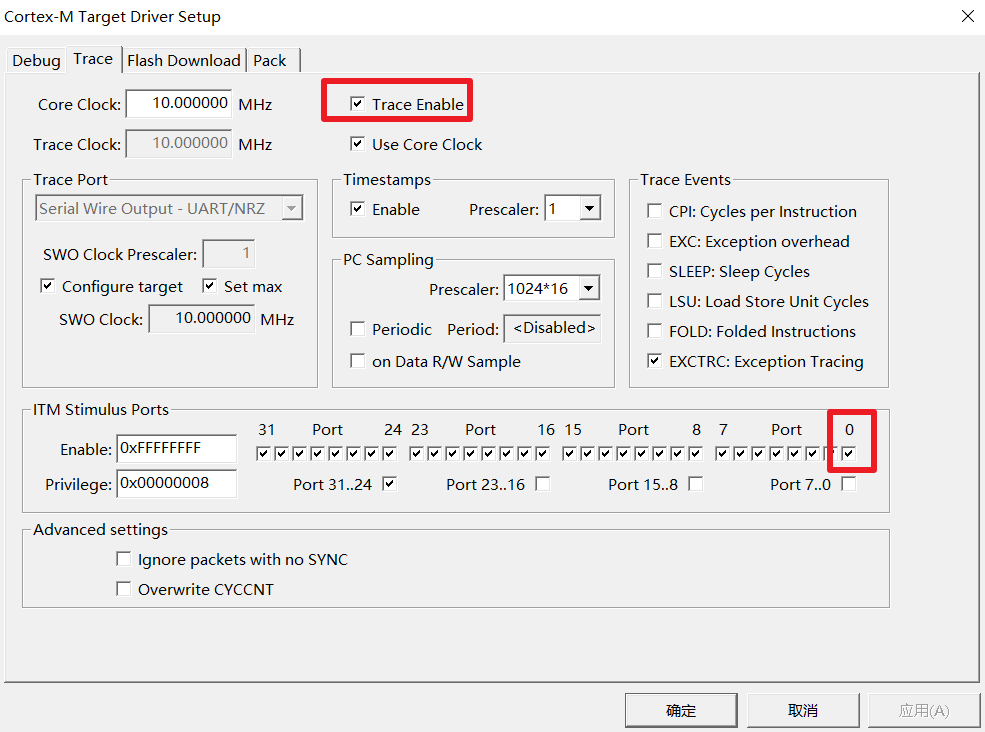
The output log can be seen in the window:
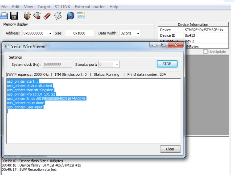
2 output through STM32 ST-LINK Utility
There is no need to make special settings to use STM32 ST-LINK Utility. Directly open Printf via SWO viewer under the ST-LINK menu, and then press start:
Output log through serial port
The above methods are used when the serial port log cannot be used temporarily or only temporarily. For long-term use, you still need to output the log through the serial port. After all, you can't connect the emulator most of the time.
To add serial port output log, you only need to add the set of operation functions of the serial port:
typedef struct {
    volatile u8     type;
    u8*             buffer;
    volatile u32    write_idx;
    volatile u32    read_idx;
    volatile u32    dma_read_idx;
    //uart
    log_func*       uart_log_func;
    //SWO
    log_func*       swo_log_func;
}log_dev;
Implement serial port driver function:
log_func uart_log_func = {
    uart_log_init,
    uart_print_ch,
    0,
};
Adding serial port output log is similar to the process through SWO, so I won't describe it more. The problem to be discussed below is that the speed of serial port is low and the output data takes a long time, which seriously affects the operation of the system. Although the impact can be mitigated by printing to SRAM first and then delaying the output, if the system interrupts frequently or requires time-consuming operation, the log may be lost. To solve this problem is to solve the problem that the CPU and the output data are carried out simultaneously to the serial port. Embedded engineers can immediately think that DMA is a good solution.
Using DMA to carry log data to serial port for output without affecting CPU operation can solve the problem that the time-consuming output of serial port log affects the system: Why use DMA to send and receive data through STM32 serial port? The serial port and DMA initialization functions are as follows:
u8 uart_log_init(void* arg)
{
    DMA_InitTypeDef DMA_InitStructure;
    u32* bound = (u32*)arg;
    //GPIO port settings
    GPIO_InitTypeDef GPIO_InitStructure;
    USART_InitTypeDef USART_InitStructure;

    RCC_AHB1PeriphClockCmd(RCC_AHB1Periph_GPIOA,ENABLE); //Enable GPIOA clock
    RCC_APB1PeriphClockCmd(RCC_APB1Periph_USART2,ENABLE);//Enable USART2 clock
    //Serial port 2 corresponding pin multiplexing mapping
    GPIO_PinAFConfig(GPIOA,GPIO_PinSource2,GPIO_AF_USART2);
    //USART2 port configuration
    GPIO_InitStructure.GPIO_Pin = GPIO_Pin_2;
    GPIO_InitStructure.GPIO_Mode = GPIO_Mode_AF;//Reuse function
    GPIO_InitStructure.GPIO_Speed = GPIO_Speed_50MHz;   //Speed 50MHz
    GPIO_InitStructure.GPIO_OType = GPIO_OType_PP; //Push pull multiplex output
    GPIO_InitStructure.GPIO_PuPd = GPIO_PuPd_UP; //Pull up
    GPIO_Init(GPIOA,&GPIO_InitStructure);
 //USART2 initialization settings
    USART_InitStructure.USART_BaudRate = *bound;//Baud rate setting
    USART_InitStructure.USART_WordLength = USART_WordLength_8b;//The word length is in 8-bit data format
    USART_InitStructure.USART_StopBits = USART_StopBits_1;//A stop bit
    USART_InitStructure.USART_Parity = USART_Parity_No;//No parity bit
    USART_InitStructure.USART_HardwareFlowControl = USART_HardwareFlowControl_None;//No hardware data flow control
    USART_InitStructure.USART_Mode = USART_Mode_Tx; //Transceiver mode
    USART_Init(USART2, &USART_InitStructure); //Initialize serial port 1
#ifdef LOG_UART_DMA_EN
    USART_DMACmd(USART2,USART_DMAReq_Tx,ENABLE);
#endif
    USART_Cmd(USART2, ENABLE);  //Enable serial port 1
    USART_ClearFlag(USART2, USART_FLAG_TC);
    while (USART_GetFlagStatus(USART2, USART_FLAG_TC) == RESET);
#ifdef LOG_UART_DMA_EN
    RCC_AHB1PeriphClockCmd(RCC_AHB1Periph_DMA1, ENABLE);
    //Config DMA channel, uart2 TX usb DMA1 Stream6 Channel
    DMA_DeInit(DMA1_Stream6);
    DMA_InitStructure.DMA_Channel = DMA_Channel_4;
    DMA_InitStructure.DMA_PeripheralBaseAddr = (uint32_t)(&USART2->DR);
    DMA_InitStructure.DMA_DIR = DMA_DIR_MemoryToPeripheral;
    DMA_InitStructure.DMA_PeripheralInc = DMA_PeripheralInc_Disable;
    DMA_InitStructure.DMA_MemoryInc = DMA_MemoryInc_Enable;
    DMA_InitStructure.DMA_PeripheralDataSize = DMA_PeripheralDataSize_Byte;
    DMA_InitStructure.DMA_MemoryDataSize = DMA_PeripheralDataSize_Byte;
    DMA_InitStructure.DMA_Mode = DMA_Mode_Normal;
    DMA_InitStructure.DMA_Priority = DMA_Priority_High;
    DMA_InitStructure.DMA_FIFOMode = DMA_FIFOMode_Disable;
    DMA_InitStructure.DMA_MemoryBurst = DMA_MemoryBurst_Single;
    DMA_InitStructure.DMA_PeripheralBurst = DMA_PeripheralBurst_Single;
    DMA_Init(DMA1_Stream6, &DMA_InitStructure);
    RCC_AHB1PeriphClockCmd(RCC_AHB1Periph_DMA1, ENABLE);
#endif
    return 0;
}
The functions of DMA output to serial port are as follows:
u8 uart_print_dma(u8* buffer, u32 len)
{
if((DMA1_Stream6->CR & DMA_SxCR_EN) != RESET){
//dma not ready
return 1;
}
if(DMA_GetFlagStatus(DMA1_Stream6,DMA_IT_TCIF6) != RESET){
DMA_ClearFlag(DMA1_Stream6,DMA_FLAG_TCIF6);
DMA_Cmd(DMA1_Stream6,DISABLE);
}
DMA_SetCurrDataCounter(DMA1_Stream6,len);
DMA_MemoryTargetConfig(DMA1_Stream6, (u32)buffer, DMA_Memory_0);
DMA_Cmd(DMA1_Stream6,ENABLE);
return 0;
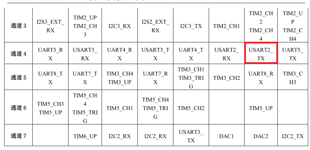
}In order to facilitate the direct use of the query DMA status register, the DMA interrupt mode can be modified if necessary. Check the Datasheet to find the stream6 of serial port 2 using dma1 channel 4:
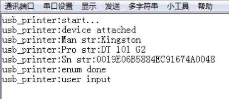
Finally, the serial port assistant on the PC side can see the log output:
DMA is used to carry the data in the log buffer to the serial port, and the CPU can handle other things. This method has the least impact on the system and outputs the log in time. It is the most used method in practical use. In addition, not only the serial port can be used, but also other DMA interfaces (such as SPI and USB) can use this method to print log.
Use IO analog serial port to output log
Finally, we need to discuss how to output log when there is no serial port in some packages or the serial port has been used for other purposes. At this time, we can find a free ordinary IO to simulate the serial port tool of UART protocol to output log to the upper computer.
The commonly used UART protocols are as follows:

The output time of the serial port can be determined as long as the output time of the analog waveform is high or low.
In order to obtain accurate delay, TIM4 timer is used to generate 1us delay. Note: the timer cannot be reused. TIM2 and tim3 are used in the test project. If it is reused, it will be disordered.
The initialization function is as follows:
u8 simu_log_init(void* arg)
{
    TIM_TimeBaseInitTypeDef TIM_InitStructure;
    u32* bound = (u32*)arg;
    //GPIO port settings
    GPIO_InitTypeDef GPIO_InitStructure;
    RCC_AHB1PeriphClockCmd(RCC_AHB1Periph_GPIOA,ENABLE); //Enable GPIOA clock
    GPIO_InitStructure.GPIO_Pin = GPIO_Pin_2;
    GPIO_InitStructure.GPIO_Mode = GPIO_Mode_OUT;
    GPIO_InitStructure.GPIO_Speed = GPIO_Speed_50MHz;   //Speed 50MHz
    GPIO_InitStructure.GPIO_OType = GPIO_OType_PP; //Push pull multiplex output
    GPIO_InitStructure.GPIO_PuPd = GPIO_PuPd_UP; //Pull up
    GPIO_Init(GPIOA,&GPIO_InitStructure);
    GPIO_SetBits(GPIOA, GPIO_Pin_2);
    //Config TIM
    RCC_APB1PeriphClockCmd(RCC_APB1Periph_TIM4,ENABLE); //Enable TIM4 clock
    TIM_DeInit(TIM4);
    TIM_InitStructure.TIM_Prescaler = 1;        //2 frequency division
    TIM_InitStructure.TIM_CounterMode = TIM_CounterMode_Up;
    TIM_InitStructure.TIM_Period = 41;          //1us timer
    TIM_InitStructure.TIM_ClockDivision = TIM_CKD_DIV1;
    TIM_TimeBaseInit(TIM4, &TIM_InitStructure);
    TIM_ClearFlag(TIM4, TIM_FLAG_Update);
    baud_delay = 1000000/(*bound);          //Calculate the delay of each bit according to the baud rate
    return 0;
}
The delay function using the timer is:
void simu_delay(u32 us)
{
    volatile u32 tmp_us = us;
    TIM_SetCounter(TIM4, 0);
    TIM_Cmd(TIM4, ENABLE);
    while(tmp_us--){
        while(TIM_GetFlagStatus(TIM4, TIM_FLAG_Update) == RESET);
        TIM_ClearFlag(TIM4, TIM_FLAG_Update);
    }
    TIM_Cmd(TIM4, DISABLE);
}
Finally, the analog output function. Note: the interrupt must be turned off before output, and a byte must be turned on after output, otherwise garbled code will appear:
u8 simu_print_ch(u8 ch)
{
   volatile u8 i=8;
   __asm("cpsid i");
   //start bit
   GPIO_ResetBits(GPIOA, GPIO_Pin_2);
   simu_delay(baud_delay);
   while(i--){
           if(ch & 0x01)
               GPIO_SetBits(GPIOA, GPIO_Pin_2);
           else
               GPIO_ResetBits(GPIOA, GPIO_Pin_2);
           ch >>= 1;
           simu_delay(baud_delay);
   }
   //stop bit
   GPIO_SetBits(GPIOA, GPIO_Pin_2);
   simu_delay(baud_delay);
   simu_delay(baud_delay);
   __asm("cpsie i");
   return 0;
}
This paper introduces several methods of printing debugging information used in development. The method is always dead, and the key is to use it flexibly; Printing effective debugging information can help solve the problems encountered in development and later maintenance and avoid detours.
If you are in the project and have no serial port cable, how will you debug it? Please state your thoughts in the comments section.