Catalogue of series articles
Github open source address
Write STM32F103C8T6 driver library from scratch (I) -- STM32CubeMX create and adjust engineering structure
Write STM32F103C8T6 driver library from scratch (II) -- write system initialization program and configure clock tree
Write STM32F103C8T6 driver library from scratch (III) -- write GPIO driver
preface
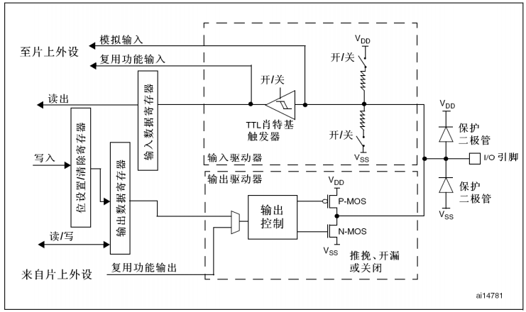
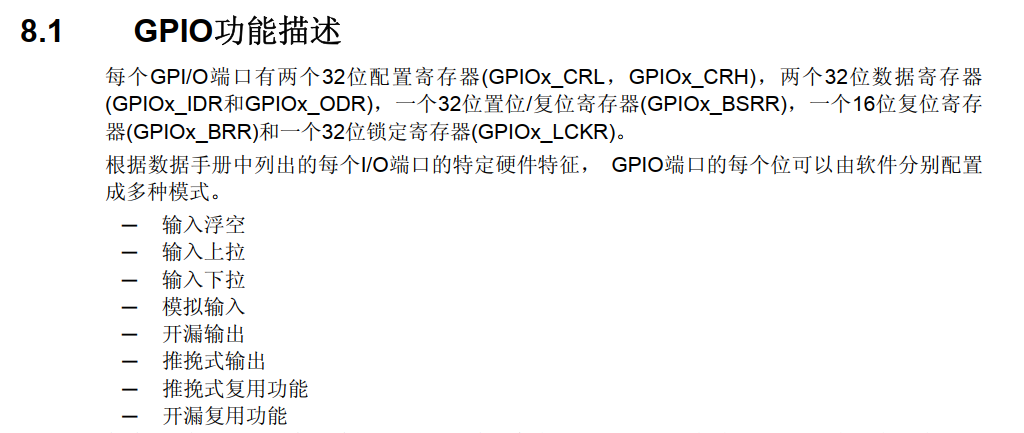
Basic structure of I/O port bit
1. Create a file
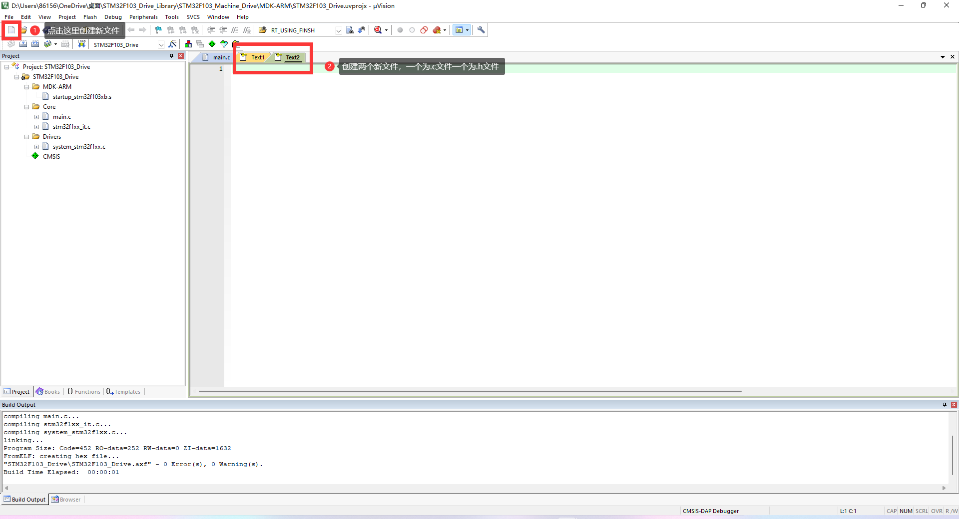
Click the New icon in the upper left corner to create two New files, one as c file as a h file
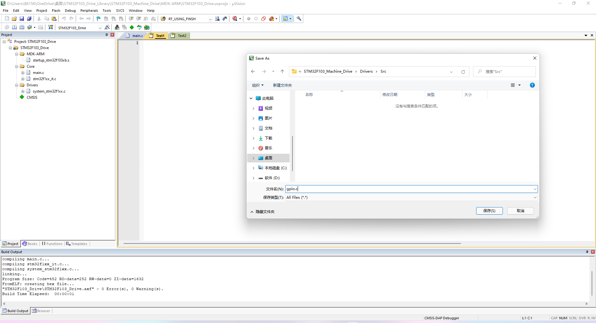
Press ctrl+s to save the file, save it to the Drivers/Src path, and name it GPIO c
Similarly, save another file to Drivers/Inc and name it GPIO h
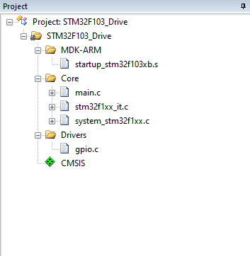
2. Add to project
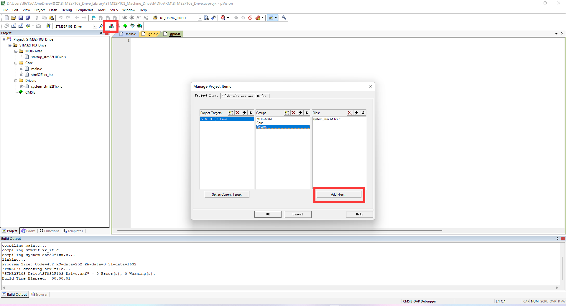
Click file management to open GPIO C added to the project and system_stm32f1xx.c moves to the Core folder, and the adjusted path results are as follows.
3. Add document notes
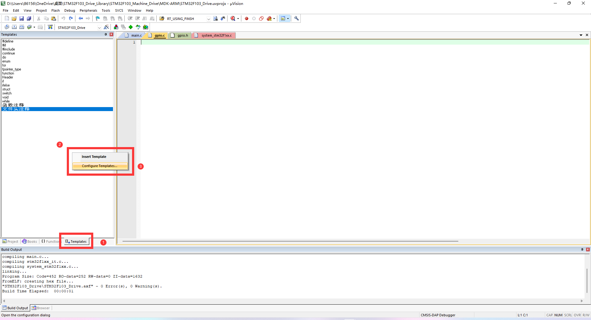
You can right-click the blank space in Templates to configure your own notes
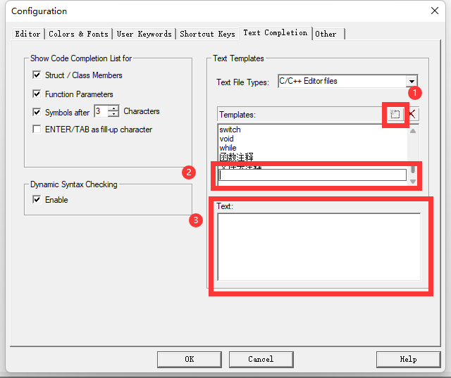
Just fill in the note name in 2 places and the note information in 3 places to write notes quickly
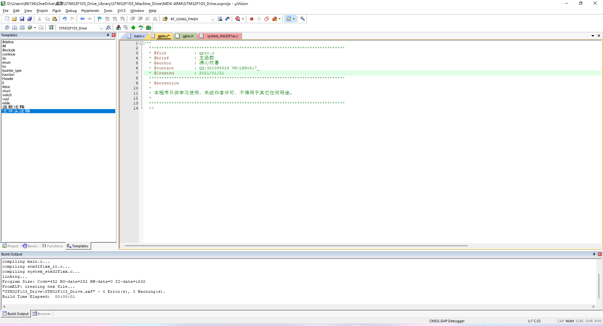
Let's add it c documents and Note information of h file
4. Add h file to prevent repeated compilation
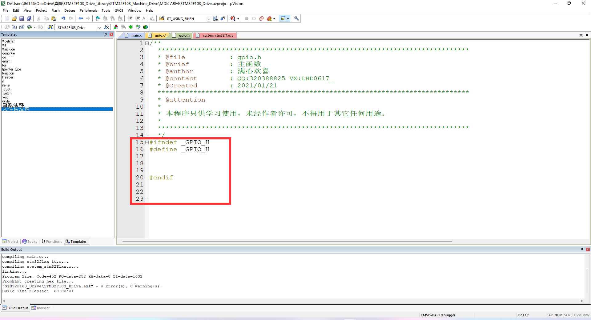
We use a macro definition to prevent GPIO h file is compiled repeatedly, which roughly means that if there is no definition_ GPIO_H macro, then define the macro and start compiling h file. If the macro has been defined when compiling the file for the second time, the second compilation will not be carried out.
5. Create a new common file common h
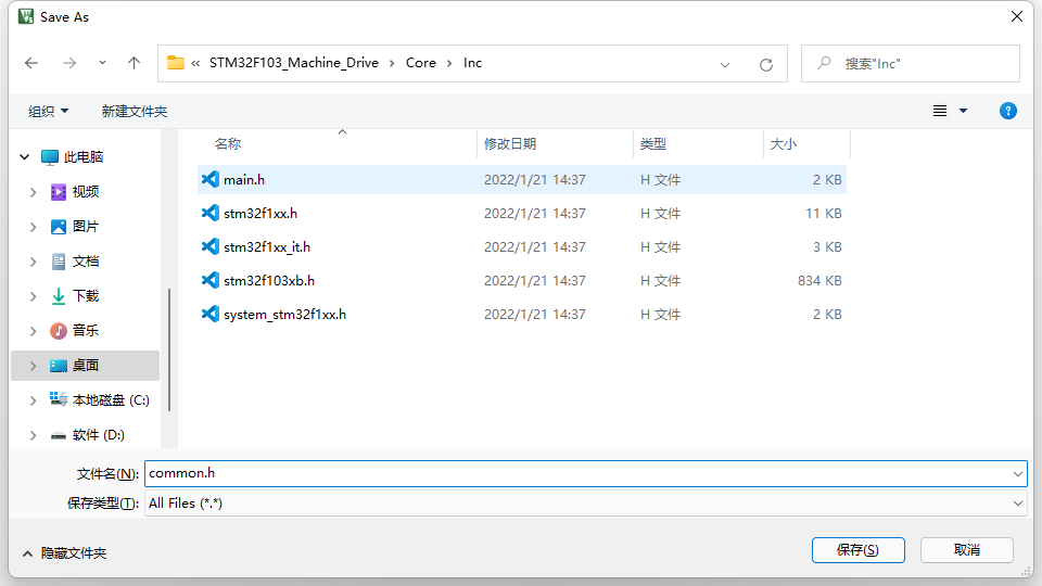
In the same way, we save it in the Core/Inc folder. The main codes are as follows.
/**
  ******************************************************************************
  * @file           : common.h
  * @brief          : General header file
	* @author					: Full of joy
	* @contact				: QQ:320388825 VX:LHD0617_
	* @Created				: 2021/01/21
  ******************************************************************************
  * @attention
  *
  * This program is only for learning and can not be used for any other purpose without the permission of the author.
  *
  ******************************************************************************
  */
#ifndef _COMMON_H
#define _COMMON_H

//Data type declaration
typedef unsigned char							uint8;													//  8 bits
typedef unsigned short int						uint16;													// 16 bits
typedef unsigned long int						uint32;													// 32 bits
typedef unsigned long long						uint64;													// 64 bits

typedef char									int8;														//  8 bits
typedef short int								int16;													// 16 bits
typedef long  int								int32;													// 32 bits
typedef long  long								int64;													// 64 bits

typedef volatile int8							vint8;													//  8 bits
typedef volatile int16							vint16;													// 16 bits
typedef volatile int32							vint32;													// 32 bits
typedef volatile int64							vint64;													// 64 bits

typedef volatile uint8							vuint8;													//  8 bits
typedef volatile uint16							vuint16;												// 16 bits
typedef volatile uint32							vuint32;												// 32 bits
typedef volatile uint64							vuint64;												// 64 bits


#endif
6.gpio.h documentation
gpio.h file mainly stores some header files, enumeration types, function declarations and macro definitions
- First, we need to introduce two header files
#include "stm32f1xx.h"
#include "common.h"
stm32f1xx.h is the stm32 register macro definition file
common.h is the general header file we just created. Its main content is the alias of data type.
- Define MCU pin enumeration type
/*Set pin enumeration type*/
typedef enum
{
    PA0,  PA1,  PA2,  PA3,  PA4,  PA5,  PA6,  PA7,  PA8,  PA9,  PA10, PA11, PA12, PA13, PA14, PA15,

    PB0,  PB1,  PB2,  PB3,  PB4,  PB5,  PB6,  PB7,  PB8,  PB9,  PB10, PB11, PB12, PB13, PB14, PB15,

    PC0,  PC1,  PC2,  PC3,  PC4,  PC5,  PC6,  PC7,  PC8,  PC9,  PC10, PC11, PC12, PC13, PC14, PC15,
}GPIO_Num;
- Define IO port direction enumeration type
/*Set IO port direction enumeration type*/
typedef enum
{
	GPI,										// Define pin input
	GPO,										// Define pin output
}GPIO_Dir;
- Define the IO port mode enumeration type. The value of the enumeration type is the value to be written to the register in the future
/*Set IO port mode enumeration type*/
typedef enum
{
	GPI_ANAOG_IN 			=	0x00,						// Define pin analog input
	GPI_FLOATING_IN			=	0x04,						// Define pin float input
	GPI_PULL_UD				=	0x08,						// Define pin pull-down input

	GPO_PUSH_PULL			=	0x00,						// Define pin push-pull output
	GPO_OPEN_DTAIN			=	0x04,						// Define pin open drain output
	GPO_AF_PUSH_PULL		=	0x08,						// Define pin reuse push-pull output
	GPO_AF_OPEN_DTAIN		=	0x0C,						// Define pin multiplex open drain output

}GPIO_Mode;
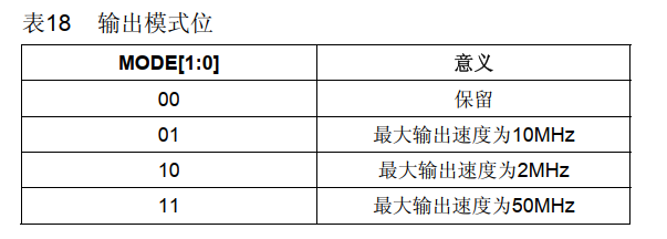
- Defines the IO port speed enumeration type. The value of the enumeration type is the value to be written to the register in the future
/*Set IO port speed enumeration type*/
typedef enum
{
		GPIO_SPEED_2MHZ		= 	0x02,
		GPIO_SPEED_10MHZ	=	0x01,
		GPIO_SPEED_50MHZ	=	0x03,
}GPIO_Speed;
- Define the IO port pin module number
We know that the enumeration type in C language is also a number and can also participate in the operation. That is to say, PA0 is 0, PA1 is 1 and PB0 is 16.
Because each pin module has sixteen pins (0-15), the module number of the pin can be obtained by moving the pin 4 bits to the right
/*Get pin module number (A,B,C)*/
#define Get_Region(pin)		(pin>>4)
- Get pin number
The lower four digits of the pin are the serial number of the pin, so we only need to match the pin and 0x0F to get the pin number
/*Get pin serial number*/
#define Get_Pin(pin)			(pin&0x0f)
7.GPIO initialization function
- First, we need to define a GPIO register array, so that we can configure the registers through the array serial number
GPIO_TypeDef *gpio_group[4] = {GPIOA, GPIOB, GPIOC, GPIOD};
- Define function
void gpio_init(GPIO_Num pin, GPIO_Dir dir, uint8 dat, GPIO_Mode mode, GPIO_Speed speed)
I define the function name as GPIO_ Of course, you can use the name init as you like. Then input the parameters required for GPIO initialization: pin, direction, initial level, GPIO mode and pin speed.
- Get pin module number and pin number
uint8 Reg = Get_Region(pin);
uint8 Pin = Get_Pin(pin);
- Enable corresponding GPIO clock
Because of the consideration of system energy saving, the chip reset is to turn off all peripheral clocks by default. The user needs to use the clock and turn on the clock by himself
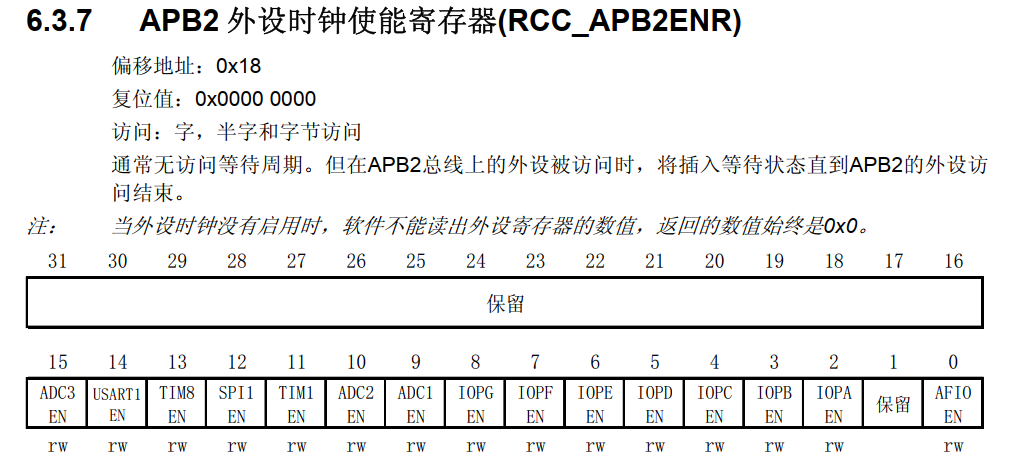
Since all GPIO clocks are mounted on the APB2 peripheral bridge, we only need to obtain the pin number and offset it on the GPIOA
RCC->APB2ENR |= 0x01<<(2+Reg);
- GPIO mode configuration
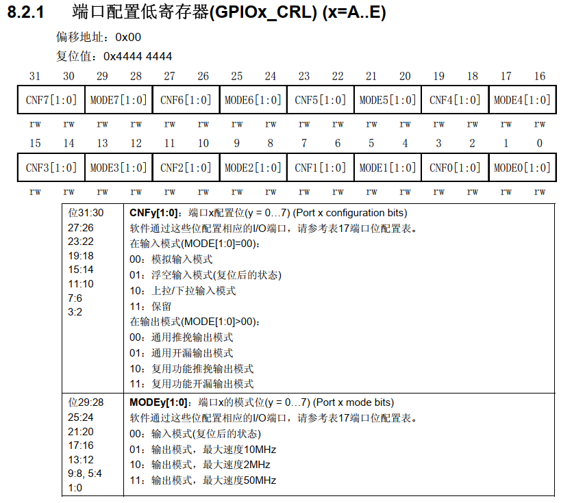
The configuration of GPIO mode is controlled by CRL and CRH registers
CRL is a low eight bit register that controls GPIO0-GPIO7
CRH is the high eight bit register control GPIO8-GPIO15
If we want to configure GPIO as the up-down input mode, we write the two bits of mode to 00 and configure the two bits of CNFy to 10
If we want to configure GPIO to push-pull output mode, we write two bits of mode to 11 and two bits of CNFy to 00
Clear the corresponding register bit before writing to the register to prevent errors.
So the code is as follows:
if(dir == GPI)
	{
		if(Pin<8)
		{
			gpio_group[Reg]->CRL &= ~(0x0f<<Pin*4);
			gpio_group[Reg]->CRL |= mode<<Pin*4;
		}
		else
		{
			gpio_group[Reg]->CRH &= ~(0x0f<<(Pin-8)*4);
			gpio_group[Reg]->CRH |= mode<<(Pin-8)*4;
		}
	}
	if(dir == GPO)
	{
		if(Pin<8)
		{
			gpio_group[Reg]->CRL &= ~(0x0f<<Pin*4);
			gpio_group[Reg]->CRL |= mode<<Pin*4;
			gpio_group[Reg]->CRL |= speed<<Pin*4;
		}
		else
		{
			gpio_group[Reg]->CRH &= ~(0x0f<<(Pin-8)*4);
			gpio_group[Reg]->CRH |= mode<<(Pin-8)*4;
			gpio_group[Reg]->CRH |= speed<<(Pin-8)*4;
		}
	}
-
GPIO output level
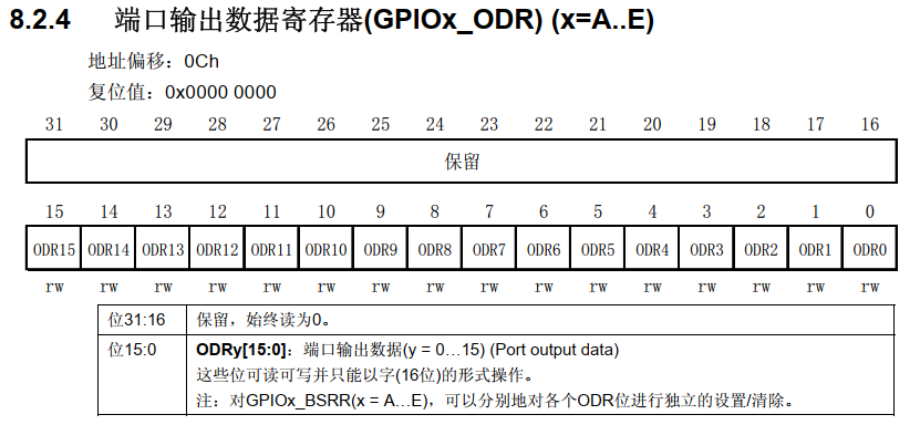
ODR register is the port output data register. If it is push-pull output mode, it is the output level. If it is input mode, it is up and down. -
In GPIO H declared in the document
void gpio_init(GPIO_Num pin, GPIO_Dir dir, uint8 dat, GPIO_Mode mode, GPIO_Speed speed);
This is the end of GPIO initialization. The complete code is as follows:
/**
	* @name		gpio_init
 	* @brief  	GPIO initialization
	* @param  	pin	Pin number 		 (P(A,B,C)0-15)
	* @param  	dir	Pin direction 		 GPO output 	 GPI input
	* @param  	dat	Initialization level 	 0 is low level 	 1 is high level
	* @param  	mode	Pin mode 		 In GPIO H files can be selected
	* @param  	speed	Output rate 		 In GPIO H files can be selected
	* @return 	void
	* @Sample 	gpio_init(PC13, GPO, 0, GPO_PUSH_PULL, GPIO_SPEED_50MHZ)
	* @Sample 	gpio_init(PC13, GPI, 1, GPI_PULL_UD	 , GPIO_SPEED_50MHZ)
  */
void gpio_init(GPIO_Num pin, GPIO_Dir dir, uint8 dat, GPIO_Mode mode, GPIO_Speed speed)
{
	uint8 Reg = Get_Region(pin);
	uint8 Pin = Get_Pin(pin);
	RCC->APB2ENR |= 0x01<<(2+Reg);
	if(dir == GPI)
	{
		if(Pin<8)
		{
			gpio_group[Reg]->CRL &= ~(0x0f<<Pin*4);
			gpio_group[Reg]->CRL |= mode<<Pin*4;
		}
		else
		{
			gpio_group[Reg]->CRH &= ~(0x0f<<(Pin-8)*4);
			gpio_group[Reg]->CRH |= mode<<(Pin-8)*4;
		}
	}
	if(dir == GPO)
	{
		if(Pin<8)
		{
			gpio_group[Reg]->CRL &= ~(0x0f<<Pin*4);
			gpio_group[Reg]->CRL |= mode<<Pin*4;
			gpio_group[Reg]->CRL |= speed<<Pin*4;
		}
		else
		{
			gpio_group[Reg]->CRH &= ~(0x0f<<(Pin-8)*4);
			gpio_group[Reg]->CRH |= mode<<(Pin-8)*4;
			gpio_group[Reg]->CRH |= speed<<(Pin-8)*4;
		}
	}
	if(dat)	gpio_group[Reg]->ODR |= 0x01<<Pin;
	else	gpio_group[Reg]->ODR &= ~(0x01<<Pin);
}
8. Set pin level function
This function has nothing to say but to set the value in the corresponding ODR register. The code is as follows:
/**
	* @name		gpio_set
  	* @brief  	GPIO Set pin level
	* @param  	pin		Pin number 		 (P(A,B,C)0-15)
	* @param  	dat		Initialization level 	 0 is low level 	 1 is high level
	* @return 	void
	* @Sample 	gpio_set(PC13, 0)
  */
void gpio_set(GPIO_Num pin, uint8 dat)
{
	if(dat)	gpio_group[Get_Region(pin)]->ODR |= 0x01<<Get_Pin(pin);
	else	gpio_group[Get_Region(pin)]->ODR &= ~(0x01<<Get_Pin(pin));
}
9. Read pin level function
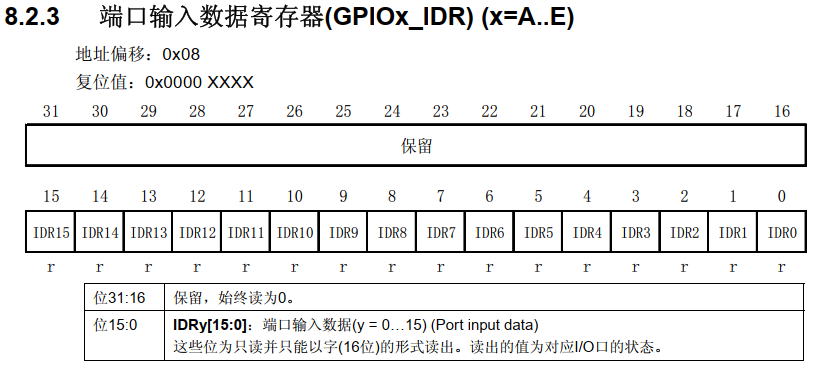
Just read the value in the IDR register of the corresponding pin. The code is as follows:
/**
	* @name		gpio_get
  	* @brief  	GPIO Get pin level
	* @param  	pin		Pin number 		 (P(A,B,C)0-15)
	* @return 	Pin level 	 0 is low level and 1 is high level
	* @Sample 	gpio_get(PA0)
  */
uint8 gpio_get(GPIO_Num pin)
{
	if(gpio_group[Get_Region(pin)]->IDR & 0x01<<Get_Pin(pin))		return 1;
	else															return 0;
}
10. Set the pin direction function
This function is often used in software analog communication timing. In fact, it is an initialization function. On the basis of removing the enable clock and configuring the pin level, the code is as follows:
/**
	* @name		gpio_dir
	* @brief  	GPIO Set pin direction
	* @param  	pin		Pin number 		 (P(A,B,C)0-15)
	* @param  	dir		Pin direction 		 GPO output 	 GPI input
	* @param  	mode	Pin mode 		 In GPIO H optional in file
	* @param  	speed	Output rate 		 In GPIO H files can be selected
	* @return 	void
	* @Sample 	gpio_dir(PC13, GPO, GPO_PUSH_PULL, GPIO_SPEED_50MHZ)
	* @Sample	gpio_dir(PC13, GPI, GPI_PULL_UD  , GPIO_SPEED_50MHZ)
  */
void gpio_dir(GPIO_Num pin, GPIO_Dir dir, GPIO_Mode mode, GPIO_Speed speed)
{
	uint8 Reg = Get_Region(pin);
	uint8 Pin = Get_Pin(pin);
	if(dir == GPI)
	{
		if(Pin<8)
		{
			gpio_group[Reg]->CRL &= ~(0x0f<<Pin*4);
			gpio_group[Reg]->CRL |= mode<<Pin*4;
		}
		else
		{
			gpio_group[Reg]->CRH &= ~(0x0f<<(Pin-8)*4);
			gpio_group[Reg]->CRH |= mode<<(Pin-8)*4;
		}
	}
	if(dir == GPO)
	{
		if(Pin<8)
		{
			gpio_group[Reg]->CRL &= ~(0x0f<<Pin*4);
			gpio_group[Reg]->CRL |= mode<<Pin*4;
			gpio_group[Reg]->CRL |= speed<<Pin*4;
		}
		else
		{
			gpio_group[Reg]->CRH &= ~(0x0f<<(Pin-8)*4);
			gpio_group[Reg]->CRH |= mode<<(Pin-8)*4;
			gpio_group[Reg]->CRH |= speed<<(Pin-8)*4;
		}
	}
}
11. Pin flip level function
This function reverses the corresponding bit in the ODR register
Here I use an XOR operation to XOR 0x01 with the corresponding bit. The XOR operation is the same as 0 but different as 1
The truth table is as follows:
| Register corresponding bit | 0x01 | result |
|---|---|---|
| 1 | 1 | 0 |
| 0 | 1 | 1 |
The code is as follows:
/**
	* @name		gpio_reverse
  	* @brief  	GPIO Pin flip level
	* @param  	pin		Pin number 		 (P(A,B,C)0-15)
	* @return 	void
	* @Sample 	gpio_reverse(PC13)
  */
void gpio_reverse(GPIO_Num pin)
{
	gpio_group[Get_Region(pin)]->ODR ^= 0x01<<Get_Pin(pin);
}
12. Complete procedure
Full GPIO C Documents
/**
  ******************************************************************************
  * @file           : gpio.c
  * @brief          : GPIO drive
	* @author					: Full of joy
	* @contact				: QQ:320388825 VX:LHD0617_
	* @Created				: 2021/12/30
  ******************************************************************************
  * @attention
  *
  * This program is only for learning and can not be used for any other purpose without the permission of the author.
  *
  ******************************************************************************
  */

/* Includes ------------------------------------------------------------------*/
#include "gpio.h"

GPIO_TypeDef *gpio_group[4] = {GPIOA, GPIOB, GPIOC, GPIOD};


/**
	* @name		gpio_init
  * @brief  GPIO initialization
	* @param  pin		Pin number 		 (P(A,B,C)0-15)
	* @param  dir		Pin direction 		 GPO output 	 GPI input
	* @param  dat		Initialization level 	 0 is low level 	 1 is high level
	* @param  mode	Pin mode 		 In GPIO H files can be selected
	* @param  speed	Output rate 		 In GPIO H files can be selected
	* @return void
	* @Sample gpio_init(PC13, GPO, 0, GPO_PUSH_PULL, GPIO_SPEED_50MHZ)
	* @Sample gpio_init(PC13, GPI, 1, GPI_PULL_UD	 , GPIO_SPEED_50MHZ)
  */
void gpio_init(GPIO_Num pin, GPIO_Dir dir, uint8 dat, GPIO_Mode mode, GPIO_Speed speed)
{
	uint8 Reg = Get_Region(pin);
	uint8 Pin = Get_Pin(pin);
	RCC->APB2ENR |= 0x01<<(2+Reg);
	if(dir == GPI)
	{
		if(Pin<8)
		{
			gpio_group[Reg]->CRL &= ~(0x0f<<Pin*4);
			gpio_group[Reg]->CRL |= mode<<Pin*4;
		}
		else
		{
			gpio_group[Reg]->CRH &= ~(0x0f<<(Pin-8)*4);
			gpio_group[Reg]->CRH |= mode<<(Pin-8)*4;
		}
	}
	if(dir == GPO)
	{
		if(Pin<8)
		{
			gpio_group[Reg]->CRL &= ~(0x0f<<Pin*4);
			gpio_group[Reg]->CRL |= mode<<Pin*4;
			gpio_group[Reg]->CRL |= speed<<Pin*4;
		}
		else
		{
			gpio_group[Reg]->CRH &= ~(0x0f<<(Pin-8)*4);
			gpio_group[Reg]->CRH |= mode<<(Pin-8)*4;
			gpio_group[Reg]->CRH |= speed<<(Pin-8)*4;
		}
	}
	if(dat)	gpio_group[Reg]->ODR |= 0x01<<Pin;
	else		gpio_group[Reg]->ODR &= ~(0x01<<Pin);
}

/**
	* @name		gpio_set
  * @brief  GPIO Set pin level
	* @param  pin		Pin number 		 (P(A,B,C)0-15)
	* @param  dat		Initialization level 	 0 is low level 	 1 is high level
	* @return void
	* @Sample gpio_set(PC13, 0)
  */
void gpio_set(GPIO_Num pin, uint8 dat)
{
	if(dat)	gpio_group[Get_Region(pin)]->ODR |= 0x01<<Get_Pin(pin);
	else		gpio_group[Get_Region(pin)]->ODR &= ~(0x01<<Get_Pin(pin));
}

/**
	* @name		gpio_get
  * @brief  GPIO Get pin level
	* @param  pin		Pin number 		 (P(A,B,C)0-15)
	* @return Pin level 	 0 is low level and 1 is high level
	* @Sample gpio_get(PA0)
  */
uint8 gpio_get(GPIO_Num pin)
{
	if(gpio_group[Get_Region(pin)]->IDR & 0x01<<Get_Pin(pin))		return 1;
	else																												return 0;
}

/**
	* @name		gpio_dir
  * @brief  GPIO Set pin direction
	* @param  pin		Pin number 		 (P(A,B,C)0-15)
	* @param  dir		Pin direction 		 GPO output 	 GPI input
	* @param  mode	Pin mode 		 In GPIO H files can be selected
	* @param  speed	Output rate 		 In GPIO H files can be selected
	* @return void
	* @Sample gpio_dir(PC13, GPO, GPO_PUSH_PULL, GPIO_SPEED_50MHZ)
	* @Sample	gpio_dir(PC13, GPI, GPI_PULL_UD  , GPIO_SPEED_50MHZ)
  */
void gpio_dir(GPIO_Num pin, GPIO_Dir dir, GPIO_Mode mode, GPIO_Speed speed)
{
	uint8 Reg = Get_Region(pin);
	uint8 Pin = Get_Pin(pin);
	if(dir == GPI)
	{
		if(Pin<8)
		{
			gpio_group[Reg]->CRL &= ~(0x0f<<Pin*4);
			gpio_group[Reg]->CRL |= mode<<Pin*4;
		}
		else
		{
			gpio_group[Reg]->CRH &= ~(0x0f<<(Pin-8)*4);
			gpio_group[Reg]->CRH |= mode<<(Pin-8)*4;
		}
	}
	if(dir == GPO)
	{
		if(Pin<8)
		{
			gpio_group[Reg]->CRL &= ~(0x0f<<Pin*4);
			gpio_group[Reg]->CRL |= mode<<Pin*4;
			gpio_group[Reg]->CRL |= speed<<Pin*4;
		}
		else
		{
			gpio_group[Reg]->CRH &= ~(0x0f<<(Pin-8)*4);
			gpio_group[Reg]->CRH |= mode<<(Pin-8)*4;
			gpio_group[Reg]->CRH |= speed<<(Pin-8)*4;
		}
	}
}

/**
	* @name		gpio_reverse
  * @brief  GPIO Pin flip level
	* @param  pin		Pin number 		 (P(A,B,C)0-15)
	* @return void
	* @Sample gpio_reverse(PC13)
  */
void gpio_reverse(GPIO_Num pin)
{
	gpio_group[Get_Region(pin)]->ODR ^= 0x01<<Get_Pin(pin);
}
Full GPIO H file
/**
  ******************************************************************************
  * @file           : gpio.h
  * @brief          : GPIO drive
	* @author					: Full of joy
	* @contact				: QQ:320388825 VX:LHD0617_
	* @Created				: 2021/12/30
  ******************************************************************************
  * @attention
  *
  * This program is only for learning and can not be used for any other purpose without the permission of the author.
  *
  ******************************************************************************
  */
#ifndef _GPIO_H
#define _GPIO_H

/* Includes ------------------------------------------------------------------*/
#include "stm32f1xx.h"
#include "common.h"

/*Set pin enumeration type*/
typedef enum
{
    PA0,  PA1,  PA2,  PA3,  PA4,  PA5,  PA6,  PA7,  PA8,  PA9,  PA10, PA11, PA12, PA13, PA14, PA15,

    PB0,  PB1,  PB2,  PB3,  PB4,  PB5,  PB6,  PB7,  PB8,  PB9,  PB10, PB11, PB12, PB13, PB14, PB15,

    PC0,  PC1,  PC2,  PC3,  PC4,  PC5,  PC6,  PC7,  PC8,  PC9,  PC10, PC11, PC12, PC13, PC14, PC15,
}GPIO_Num;

/*Set IO port direction enumeration type*/
typedef enum
{
	GPI,										// Define pin input
	GPO,										// Define pin output
}GPIO_Dir;

/*Set IO port mode enumeration type*/
typedef enum
{
	GPI_ANAOG_IN 				= 	0x00,						// Define pin analog input
	GPI_FLOATING_IN				= 	0x04,						// Define pin float input
	GPI_PULL_UD					= 	0x08,						// Define pin pull-down input

	GPO_PUSH_PULL				=	0x00,						// Define pin push-pull output
	GPO_OPEN_DTAIN				= 	0x04,						// Define pin open drain output
	GPO_AF_PUSH_PULL			=	0x08,						// Define pin reuse push-pull output
	GPO_AF_OPEN_DTAIN			= 	0x0C,						// Define pin multiplex open drain output

}GPIO_Mode;

/*Set IO port speed enumeration type*/
typedef enum
{
		GPIO_SPEED_2MHZ		= 	0x02,
		GPIO_SPEED_10MHZ	=	0x01,
		GPIO_SPEED_50MHZ	=	0x03,
}GPIO_Speed;

/*Get pin module number (A,B,C)*/
#define Get_Region(pin)			(pin>>4)

/*Get pin serial number*/
#define Get_Pin(pin)			(pin&0x0f)


/*Function declaration*/
void gpio_init(GPIO_Num pin, GPIO_Dir dir, uint8 dat, GPIO_Mode mode, GPIO_Speed speed);
void gpio_set(GPIO_Num pin, uint8 dat);
uint8 gpio_get(GPIO_Num pin);
void gpio_dir(GPIO_Num pin, GPIO_Dir dir, GPIO_Mode mode, GPIO_Speed speed);
void gpio_reverse(GPIO_Num pin);


#endif