I won't talk about the principle of PWM here. Pulse width modulation can meet different power requirements of load by changing cycle and duty cycle.
1. PWM function of mx6ul
1. When the PWM of mx6ul is connected with the processor core, it follows the peripheral bus protocol. Between PWM and other modules, there is only clock signal (CCM module) and restart signal (SRC module) (as well as interrupt processing) and a separate output signal. The functional features are as follows:
- 16 bit up counter and clock source can be selected.
- 4X16 bit FIFO can reduce interrupt resources
- Configurable output high and low level mode
- You can roll back production or compare interrupts
1. Mx6ul provides 8 groups of PWM, and the output signal of each group can be selected through multiplexing configuration between several pins., The overall frame structure is as follows:
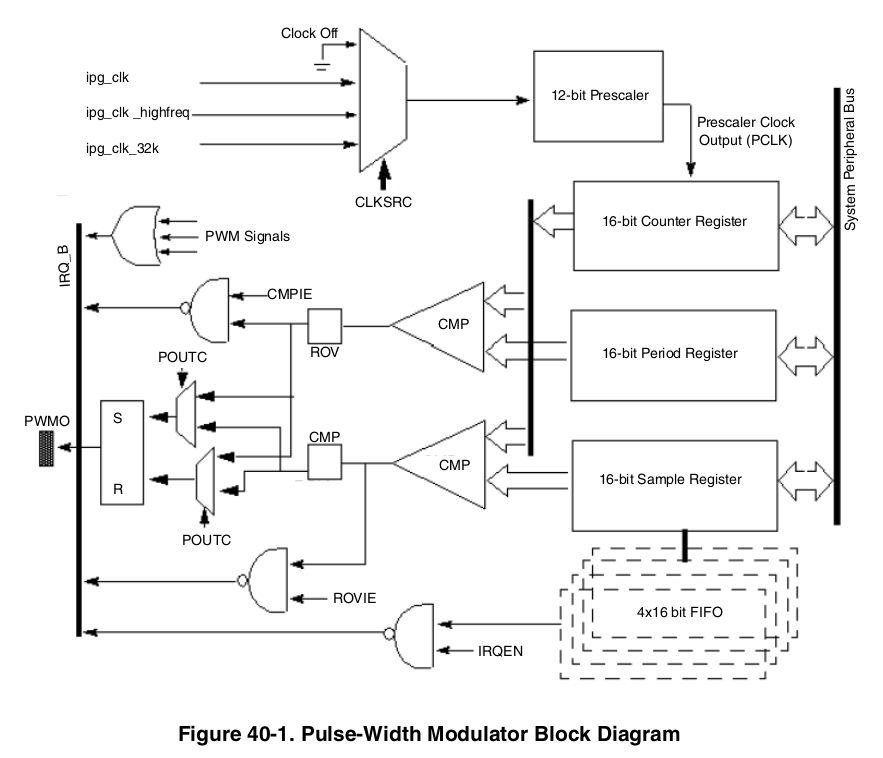
1. The PWM generation process of mx6ul is as follows:
The clock selector determines the working frequency of the counter. As before, we use the peripheral clock cycle (IPG_CLK,66MHz)
The 12 bit frequency divider can realize 1 ~ 4097 frequency division. Suppose we choose 66 frequency division, and it is 1us every time the counter counts
Period Resgiter, a 16 bit cycle register, generates an interrupt when the value of the counter is equal to the value of the cycle register (this interrupt can not be generated, similar to overflow interrupt). The counter value is equal to the cycle and is counted again from 0.
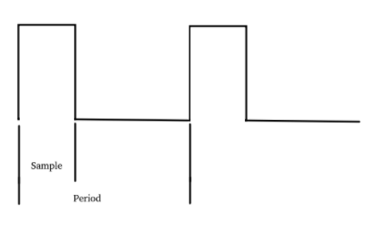
Sample Register, 16 bits. The value of this register determines the duty cycle of the signal. This is more important. Let's talk about it separately later. But it means that the signal is reversed when the value of the counter is equal to the value of the SampleRegister.
SampleRegister and FIFO
The duty cycle is handed to FIFO through SampleRegister. Note that the depth of FIFO is 4 groups, and the duty cycle of the actual signal is determined by the value of FIFO. Therefore, FIFO needs to keep writing new values to continuously generate new signals. FIFO can write at any time, but to read the value, it must be under the condition of PWM enabling. Because the depth of FIFO is 4, when writing data, pay attention to prevent overflow, otherwise FWE exception (FIFO Write Error). Similarly, we also need to detect the number of internal elements of FIFO to prevent FIFO from being empty and unable to generate new signals. This process can be generated by interrupt. When the element in FIFO is lower than the specified value, an interrupt can be generated. In the interrupt, new data is written to FIFO. A few more notes
- As long as we read the SampleRegister, the FIFO data will be reduced;
- After PWM is disabled, FIFO elements are no longer reduced;
- If PWM is soft reset, all contents in FIFO will be cleared
Rollback and compare events
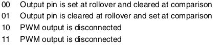
When the counter to PWM_ The value of PR register + 2 will be reset to 0 and the counting will be restarted. This process is the same as the timer interrupt counter. This event can be regarded as a rollback. During rollback, the output can be set to 0, 1 or no response according to the settings; This process can also generate an interrupt (provided that the interrupt is enabled). When the counter value accumulates to the sample value, the output state will be changed according to the setting. This is a comparison event, and an interrupt can also be triggered. In short, the signal is reversed when it reaches the Period and then reversed when it reaches the sample value to form a signal cycle.
Register description
1. The mx6ul provides 8 sets of PWM, each using 6 registers
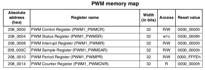
CNR, PR and SAR are three 16 bit registers that store the values of counter, Sample and Period. We won't talk about it later. Let's take a look at the rest
PWMCR
Control register,
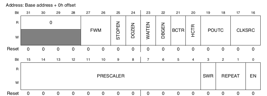
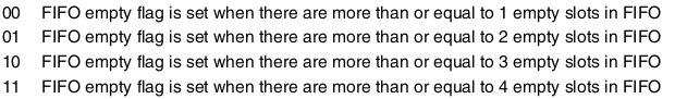
FWM [27:26]: how much FIFO remains will trigger FIFO null interrupt, which is generally set to 2. If 1 is dangerous, FIFO null error may be reported
POUTC[19:18]: output configuration, which sets the output status when rolling back and comparing events
CLKSRC[17:16]: clock source, we generally select the peripheral clock source, and the value is 01
SWR[3]: soft reset, soft reset when set to 1, and automatically return to 0 after reset
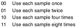
Repeat [2:1]: repeat Sample. You can set the number of times each Sample value is reused
EN[0]:PWM enable
PWMSR
Status register
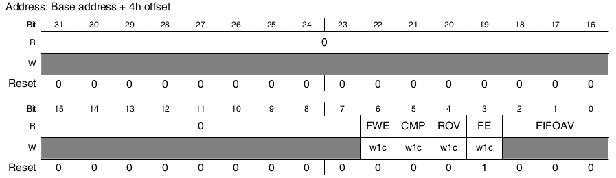
FWE[6]:FIFO write error
CMP[5]: compare events
ROV[4]: rollback event
FE[3]:FIFO empty status
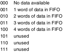
Fifoav [2:0]: number of elements in FIFO
Interrupt enable
There are three bit s available for interrupt enable
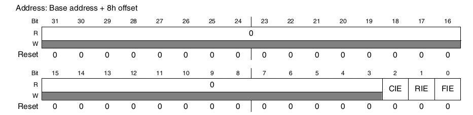
CIE[2]: compare interrupt enable
RIE[1]: rollback interrupt enable
FIE[0]:FIFO air interrupt is enabled, and the FIFO element is less than the value specified by FWM to trigger the interrupt.
PWMPR
Cycle register, calculated as follows

PWMO: PWM output signal frequency
PCLK: clock cycle after frequency division by frequency divider
period: write the value of PR register
Note that the actual period is period+1. When the value of PR written is 0xFFFF, the actual effect is the same as 0xFFFE.
Code writing
The code is very simple. The main thing is to set a global variable_ Duty, this variable will be modified every time you call to set the duty cycle. This variable is mainly used to interrupt the service. At the beginning of debugging, I forgot this variable and could not measure the output. By constantly adding print nodes, I found that only four values of duty meet the setting requirements, which should correspond to the depth of FIFO. There must be a problem with the interrupt service. Later, it was found that the value of the parameter passed when the interrupt called the function was 0.
file structure
c Documents
/**
 * @file bsp_pwm.c
 * @author your name (you@domain.com)
 * @brief
 * @version 0.1
 * @date 2022-01-22
 *
 * @copyright Copyright (c) 2022
 *
 */
#include "bsp_pwm.h"
#include "stdio.h"
unsigned char pwm_duty;

/**
 * @brief PWM1 initialization
 *
 * @param period Cycle microseconds
 * @param duty   Duty cycle
 */
void pwm1_init(unsigned int period,unsigned int duty)
{
    /**
     * IO Initialize electrical performance:
     *bit [16]      : 0 HYS close
     *bit [15:14]   : 10 100K Pull up
     *bit [13]      : 1 pull function
     *bit [12]      : 1 pull/keeper Enable
     *bit [11]      : 0 Turn off the open circuit output
     *bit [7:6]     : 10 Speed 100Mhz
     *bit [5:3]     : 010 The driving capacity is R0/2
     *bit [0]       : 0 Low conversion rate
     */
    IOMUXC_SetPinMux(IOMUXC_GPIO1_IO08_PWM1_OUT,0);
    IOMUXC_SetPinConfig(IOMUXC_GPIO1_IO08_PWM1_OUT,0xB090);

    PWM1->PWMCR = 0;                            //PWMCR Clear
    PWM1->PWMCR |= (1<<26)|(1<<16)|(65<<4);     //PWCR[27:26](FWM)=01 [17:16](CLKSRC)=01 [15:4](PRESCALER)=65

    pwm1_setperiod(period);                     //Set cycle

    for(int i=0;i<4;i++){                       //adopt SAM Register write FIFO
        pwm1_setduty(duty);                 //Constant duty cycle
    }

    PWM1->PWMIR = (1<<0);                       //FIE=1,Enable FIFO Empty interrupt
    system_register_irqHandler(PWM1_IRQn, (system_irq_handler_t)pwm1_irqhandler,NULL);  //Interrupt function registration

    GIC_EnableIRQ(PWM1_IRQn);                   //GIC Enable
    PWM1->PWMSR = 0;                            //PWMSR Register reset
    PWM1->PWMCR |= (1<<0);                      //PWMCR[0](EN)=1,Enable

}

/**
 * @brief Set cycle
 *
 * @param value
 */
void pwm1_setperiod(unsigned int value)
{
    unsigned int regvalue = 0;
    if (value<2){
        regvalue=2;
    }
    else{
        regvalue=value-2;
    }
    PWM1->PWMPR = (regvalue & 0xFFFF);
}

/**
 * @brief Set duty cycle
 *
 * @param duty Duty cycle
 */
void pwm1_setduty(unsigned char duty)
{
    unsigned short period;
    unsigned short sample;
    pwm_duty = duty;                //Don't forget this line of code, global variables pwm_duty,This variable is required to interrupt the service
    period = PWM1->PWMPR +2;
    sample = period *duty / 100;

    PWM1->PWMSAR = (sample & 0xFFFF);
}

void pwm1_irqhandler(unsigned int gcciar,void *userParam)
{
    if(PWM1->PWMSR &(1<<3)){
        pwm1_setduty(pwm_duty);
        PWM1->PWMSR |= (1<<3);
    }

}
The code is very clear. You can see the remarks directly, that is, the settings of several registers
Header file
/**
 * @file bsp_pwm.h
 * @author your name (you@domain.com)
 * @brief
 * @version 0.1
 * @date 2022-01-22
 *
 * @copyright Copyright (c) 2022
 *
 */
#ifndef __BSP_PWM_H
#define __BSP_PWM_H

#include "imx6ul.h"
#include "bsp_int.h"

void pwm1_init(unsigned int period,unsigned int duty);
void pwm1_setperiod(unsigned int value);
void pwm1_setduty(unsigned char duty);
void pwm1_irqhandler(unsigned int gcciar,void *userParam);
#endif
use
After the module is imported, it can be used in the main function
int main(void)
{
    int_init();
    imx6u_clkinit();
    clk_enable();
    delay_init();
    uart_init();
    key_init();

    unsigned char duty = 50;
    unsigned char kv = 0;

    pwm1_init(1000,duty);

    while(1){
    kv = key_getvalue();
    if(kv == KEY0_VALUE){
        duty += 5;
        if(duty>100){
            duty=5;
        }
        pwm1_setduty(duty);
        delay_ms(50);
        printf("duty:%d",duty);
        }
    }
    return 0;
}
In the main function, the key is also used, and the duty cycle increases by 5% each time the key is pressed
The cycle defined during initialization is 1000, because the clock source used is 66MHz. The frequency division is directly fixed. The value 65 corresponds to 66 frequency division. The cycle is 1000 microseconds, and the output frequency is 1KHz, which is very stable. I used a hand-held oscilloscope to measure the output value. The change process is the process of changing the duty cycle by pressing the key. I have tried this output frequency of 250K, which is very stable, but at low frequency (50Hz
The waveform is not particularly good at the time of (left and right). There is a downward trend in the high level. I don't know whether it is the cause of the oscilloscope or what.